
Embedded Systems Introductory Course
supported by remote experiments
Luis Gomes, Anikó Costa
UNINOVA / Universidade Nova de Lisboa
Faculdade de Ciências e Tecnologia
Campus de Caparica,
2829-516 Caparica, Portugal
Abstract. Laboratories for introductory digital system design courses have,
commonly, high rates of laboratory’s space and time occupation. In this paper,
a remote laboratory is proposed in order to alleviate laboratory’s occupation, al-
though increasing the usage of their equipments by students. Local and remote
accesses to the experiments are possible, supported by the LabView environ-
ment, and complemented by a specific virtual workbench adaptor to emulate
user’s presence. Its usage for supporting experimentation around a set of ex-
periments with a set-up based on the 8031 microcontroller was successfully
tested.
1 Introduction
Courses on introductory digital system design within Computer and Electrical Engi-
neering Degrees are normally taught during the first two years of the curriculum.
This is also the case at Universidade Nova de Lisboa, where the first step
(one se-
mester) covers elementary digital design, starting with Boolean algebra and related
issues and ending-up with the MSI-module (Medium Scale Integration integrated
circuit module) view of the digital system. System’s descriptions are obtained either
with truth tables and algebraic expressions (for combinatorial logic), or with state
diagrams (for sequential circuits). Common development tools include schematics
editor, state diagram editor, and logic simulators. Usage of programmable logic de-
vices (like PALs and CPLDs) can be very effective at laboratory level, as far as they
can motivate students and increase success rates [1] [2].
Next step, accomplished during another sem
ester, is devoted to introductory mi-
croprocessors and microcontrollers design. 8-bit microprocessor families receive
special attention. In order to allow an easy transition between the “MSI module-based
view of a system” and “the algorithmic view of a microprocessor-based system”, the
course starts with the structural views of the microprocessor system architecture (like
CPU, RAM, and ROM, interconnected using specific buses) and ending-up empha-
sizing the behavioral description of the system using an algorithm. The algorithm is
described using a specific notation for algorithm representation (from flowcharts to
pseudo-code), and is coded using assembly or C. In this sense, the student starts from
Gomes L. and Costa A. (2004).
Embedded Systems Introductory Course supported by remote experiments.
In Proceedings of the First International Workshop on e-Learning and Virtual and Remote Laboratories, pages 89-98
DOI: 10.5220/0001150400890098
Copyright
c
SciTePress

the hardware structural view of the system and ends-up with a behavioral characteri-
zation further implemented in software. To fill the gap between these two views, we
have been introducing microprocessor architectures using programmable logic de-
vices (CPLDs), allowing students to build-up a small didactic microprocessor (which
is based on a sub-set of the industry widely-used 8051 family), and integrate in one
small project the whole set of tools (from schematics to assembler) [3] [4].
Final step at introductory levels (also one semester) covers 16-bit microprocessors,
and explores the 80x86 architecture based on the PC platform.
From the point of view of embedded systems design, the referred courses will be
followed by additional courses at latter stages in the curriculum, covering subjects
from real-time issues to reconfigurable devices (including FPGAs), complemented by
specification formalisms (like statecharts, Petri nets and UML notations), and allow-
ing the design of SoCs (System-on-a-chip devices) using hardware-software co-
design techniques.
The emphasis of the current paper is related with the second half of the second in-
troductory course referred, where practice with 8-bit microprocessor is needed.
2 The starting point: a crowded laboratory
Roughly speaking, major laboratory assignments within our digital systems disci-
plines integrate several emphases, namely:
- Workbench instrumentation, to allow students eliminating fears associated
with the control of physical devices.
- Usage of computer aided engineering tools, grouped into two sets of tools:
- Those used for the automation of engineering design processes, from sche-
matic editors to assemblers and C compilers;
- Those used for support engineering decisions, namely simulators, more and
more important along the course (and real life) as the system complexity
increases.
The referred course is not an exception to these “general rules” and is supported by
a laboratory structured to support working teams of three students.
Students have access to ten work places and to a general-purpose programmer (for
EEPROM configuration, for instance). A networked PC and an experimental set-up
compose each work place. The PC has access to the Internet, including the discipline
website, which contains the supporting materials (from datasheets to lab assignments
descriptions and associated tools).
The experimental set-up includes power supply and testing resources (clock, inputs
and outputs), and specific breadboarded systems, ranging from a simple breadboard
(ready to receive some new experiment) to pre-prepared experiments, like the one
presented in Fig. 1 that supports the sequence of laboratory assignments referred in
this paper. It has to be noted that this set-up was intentionally left at the breadboard
level, in order to make clear to the students that the kit is something that they also can
build on their own, and through this implicit message get them closer to the experi-
ments.
88
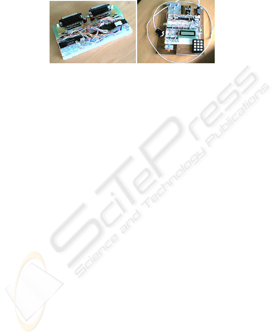
Fig. 1. Didactic microcontroller based system: basic microcontroller with RAM and EEPROM,
and a microcontrolled system with several common input-output devices (keyboard and LCD).
The set-up is based on an 8031 microcontroller, which still is widely used in indus-
try systems, surrounded by fundamental blocks, like EPROM, RAM and input-output
ports. We chose to pre-install in the EPROM, a small monitor program already in the
public domain [5], which allows download of a program into the microcontroller
memory and launches its execution afterwards. This monitor program has no special
support for debug at the hardware level (also the set-up has not as well), as most of
the program verification is accomplished using simulators (also in the public domain),
either at the assembly-code level, or at the C-code level. Due to the number of stu-
dents enrolled to the course, it is not possible to use sophisticated development tools
and environments.
The “kit” is connected, through a RS-232 serial line, to a PC, where all the devel-
opment tools are installed.
As we consider that experimentation is of major importance for students in Electri-
cal and Computer Engineering, we introduce a heavy component in laboratory as-
signments. As the number of hours that the laboratory is used for classes is high (as
the total number of students attending the course), students do not have as much op-
portunities as we would like they have to exercise on their own with the kit (even
considering a 24-hour, 7-days per week, open laboratory). In this sense, during the
hours that the laboratory is available for free use by the students, it is common to
have some conflicts regarding the usage of the reduced number of kits available at the
lab (10, in total). So, we have a major problem to solve: how to give access to the kits
to all students during a fair amount of extra classes’ time?
3 The goal: laboratory experiments anytime, anywhere
The question is not new, and was answered in different ways in the past, according to
specific additional constraints (within different disciplines).
In general terms, we like to consider three levels of exercising around a specific
experiment:
- First level is associated with physical instrumentation using a real set-up; for our
microcontroller system, it corresponds to the usage of the kit directly con-
nected to the environment under control;
89

- Second level is associated with emulation; here, we have the replacement of the
physical instrumentation by a set of input and output signals that can be exer-
cised by the student, allowing him/her to mimic the physical environment; for
our microcontroller system, it corresponds to the usage of the kit connected to
a set of testing devices (switches, push-buttons, terminals);
- Third level is associated with simulation; for our microcontroller system, it cor-
responds to the usage of a microcontroller simulator, and input/output as well.
Although first and third levels have their own role in the teaching process (and in
the system development process, as well), the second level (emulation) is the tradi-
tional level for lab experiments at introductory digital systems design.
It is in this framework that our answer to the previous question is:
Laboratory experiments? Anytime, anywhere, as much as student wants!
The “emulation goal” can be accomplished through different solutions. We con-
sider the following three solutions:
- The first solution (physical workbench) is associated with the usage of a set of
switches and push-buttons as inputs, and leds and displays as outputs;
- The second solution (virtual workbench) is the “computer aided version” of the
previous one, where the student can use a software application (complemented
with a piece of hardware to make the physical connection to the system) to
generate inputs to exercise the system and some windows to present status of
outputs;
- The third solution (remote workbench) is the “internet version” of the previous
one.
First and second solutions are local, in the sense that the student and the experi-
ment are in the same area; third solution is remote, in the sense that the student tele-
operates the experiment.
First and second solutions can be accomplished through rental (at no expense) to
the students of the necessary modules to make the testing; third solution can be ac-
complished through the usage of a set of servers that can offer remote access to the
experiments.
For the specific set of assignments around introductory microprocessor design that
we are using, and considering the number of students (180-220 per year), the third
solution seems to be a very good complement to the physical laboratory, and to labo-
ratory extensions made available through rental of kits (at no cost for students). This
paper focuses on this remote workbench solution.
4 Laboratory assignments plan
The plan for laboratory assignments for the second course on introductory digital
systems design includes two small projects. First project tries to consolidate the tran-
sition from the “MSI-module world” to the “microprocessor world”. Second project
tries to consolidate the usage of a microcontroller. For each of the two projects, a set
of preparatory exercises are foreseen.
90

The first set of preparatory exercises and the first project is supported by PLDs
(programmable logic devices), and the final achievement is a small didactic micro-
processor, that is a sub set of the 8031 microcontroller, built with a CPLD, a RAM
and an EEPROM [3] [4].
The second set of preparatory exercises and the second project is supported by the
already presented kit, based on the 8031 microcontroller. The emphasis of this paper
is around this set of exercises.
For the first set of exercises, system’s decomposition into control and data parts is
a central concept in our approach. The laboratory assignments sequence stands for
half a semester, and is composed by the following mini-project sequence:
- Introductory PLD assignment: revisit to PLD configuration using combinatorial
functions and state machines. Lab classes stands for one week (two classes of
two hours each per week).
- Introductory project: the goal is to implement a two-byte multiplier through suc-
cessive additions. Lab classes stands for two weeks.
- Intermediary project: the goal is to implement a simple calculator, able to com-
pute an expression like 2.A-B. Lab classes stands for one week.
- Preparatory project: the goal is to get acquainted with memory usage, namely
write/read data to/from RAM and read data from ROM (fundamental blocks
within microprocessor architecture). Lab classes stands for one week.
- Mini-microprocessor project: the goal is to build a didactic mini-
microprocessor, named 7½ [3] [4]. Lab classes stands for two weeks and a half.
Students need to dedicate some extra-hours to conclude the assignment.
For the second set of exercises, usage of 8031 microcontroller is the main focus.
The laboratory assignments sequence stands for half a semester, and is composed by
the following mini-project sequence:
- Introductory project I: the goal is to implement a two-byte multiplier through
successive additions using the 8031. Emphasis on simulation. Lab classes stands
for half week.
- Introductory project II: the goal is to implement a multiplier of N bytes per N
bytes, using previous results. Emphasis on simulation. Lab classes stands for
half week.
- Introductory project III: the goal is to configure and use built-in timers, and ob-
tain a square wave generator. Lab classes stands for half week.
- Introductory project IV: the goal is to configure and use the built-in serial inter-
face with a terminal. Lab classes stands for half week.
- Introductory project V: the goal is to implement the greatest common divisor,
and to test using a terminal for input-output. Lab classes stands for half week.
- Microcontroller final project: the goal is to build a complete program to be
downloaded into the 8031 kit. Lab classes stands for two weeks and a half. Stu-
dents need to dedicate some extra-hours to conclude the assignment.
The focus of our remote lab is to support the second set of experiments. For the fi-
nal project, students can choose among a set of possible applications (in the sense that
we want to get different syllabus for the different projects to be executed by the dif-
ferent groups). Those options range from computational intensive programs to input-
output intensive embedded applications. In order to get students more involved in the
91
project is also possible to choose from a set of small games (normally available in
PDAs).
In broad sense, according to their nature from time constraints point of view, three
types of projects are possible:
- First group (batch input/output): with an input/output interaction supported by a
serial line connection with a remote terminal. This is the case for the computational
intensive applications, where a set of operands is provided for processing and the
results are produced afterwards. Some of the referred introductory projects belong to
this group;
- Second group (simple input/output): control systems with simple input-output
relationships. This is the case for some automation systems, where the control is man-
aged through a state machine, which imposes a behavior evolution based on the re-
ceived inputs. As an example, we can refer embedded systems for parking lots access
control;
- Third group (real-time input/output): control systems with complex input-
output dependencies, with real-time constraints. This is the case for systems where is
necessary an accurate timing associated with the inputs or the outputs. As an exam-
ple, we can refer the usage of an oscilloscope in the X-Y mode, used as an output
device, where the microcontroller has to handle the refreshing of the information to
be displayed.
Table 1 summarizes the dependencies between the different project’s classifica-
tions used previously in this paper. It is clear that, the referred categories can be ade-
quately supported by the proposed remote laboratory, without loss of testing capabili-
ties, except for projects with real-time constraints (where direct physical interaction
between the embedded system and the environment is mandatory).
Table 1. Experimentation associated with the different types of projects.
Input-output type
Operation type
Workshop type
for adequate
emulation support
Batch i/o
Simulation, or
Emulation, or
Physical
Physical, or
Virtual, or
Remote
Simple i/o
Simulation, or
Emulation, or
Physical
Physical, or
Virtual, or
Remote
Real-time i/o
Physical
Not applicable
92
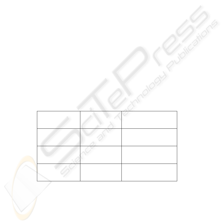
5 Remote laboratory structure
In this sense, a remote laboratory can adequately support experiments within intro-
ductory digital system design courses. For that end, we build a remote laboratory
based on a four level structure (see Fig. 2):
- Student (user), remotely connected to the local server using a browser through
the internet;
- Local server, enabling virtual workbench to be used remotely;
- Virtual workbench adaptor, which interacts with the local server in order to pro-
duce inputs to the system under test and get current status of outputs;
- Microcontroller system under test, which is our 8031 based microsystem.
ATMega 128
System
8031
System
RS-232
RESET
Virtual
Workbench
adapter
Microcontroller
system under
test
Internet
Remote access
Local Server
RS-232
ATMega 128
System
8031
System
RS-232
RESET
Virtual
Workbench
adapter
Microcontroller
system under
test
Internet
Remote access
Local Server
RS-232
Fig. 2. Remote laboratory structure.
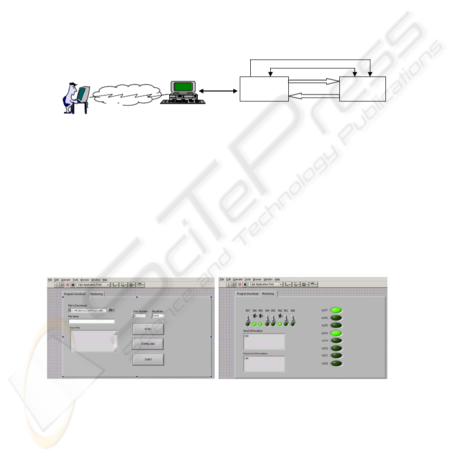
Current implementation of the local server is based on LabView, which can assure
adequate connectivity to lower levels, while taking care of the internet connectivity.
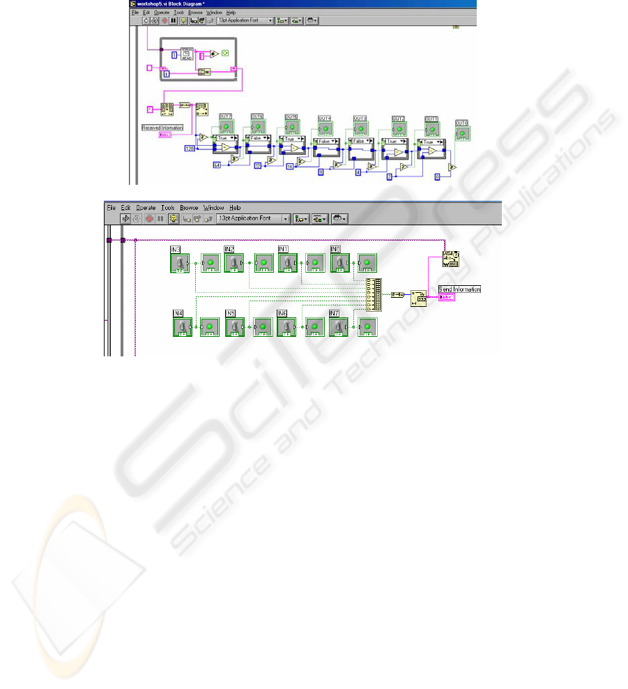
Fig. 3 presents two snapshots of the LabView vi, the first one to allow remote reset
of the system under test, followed by downloading of the program and its launching;
the second snapshot is active afterwards (and before a new reset, when the monitor
installed in the 8031 system will take again control of the system), and is used to
impose inputs and get output status from the system under test.
In this sense, the usage of the virtual workbench is very close to the procedures to
comply when interacting directly with the 8031-system.
Fig. 3. Snapshots of the virtual workbench: download of a program and monitoring of the
system under test.
Fig. 4 presents partial control flow associated with the snapshot of Fig. 3 left
(download a program), while Fig. 5 presents partial control flow associated with the
snapshot of Fig. 3 right (monitoring of the system).
93
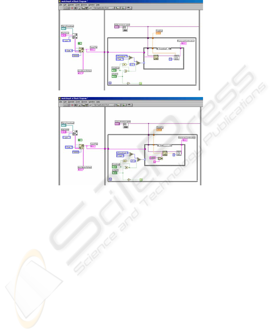
Fig. 4. Snapshots of the virtual workbench control flow: download of a program.
For the virtual workbench adaptor, a simple system based on a ATmega128 micro-
controller was developed. General features include:
- Two RS-232 links; one devoted to connect with the local server, so, to receive
commands from the user and return responses; the other is targeted to connect
with the system under test;
- A set of input to acquire actual outputs of the system under test;
- A set of outputs to impose values at the inputs of the system under test;
- A reset output to assert reset pin of the system under test (and get control back to
the monitor program).
From the point of view of connection between the local server and the workbench
adaptor, a simple protocol was defined, including the following set of commands:
- Reset of the system under test;
- Download a file to the system under test;
- Download commands and binary sequences to the system under test (command
at the upper serial link will be echoed at the lower serial link);
- Get actual status of system under test outputs;
- Impose specific values at the system under test inputs;
94
- A command to enable further use as a terminal (from local server to the system
under test, being the workbench adaptor “transparent”).
This workbench adaptor can also be used for general virtual and remote laboratory
experiments. Adaptation to different courses is currently being considered.
Fig. 5. Snapshots of the virtual workbench: monitoring of the system under test.
6 Conclusions
A remote laboratory applicable to introductory digital system design courses is pro-
posed. Its usage for supporting experimentation around a set of experiments with a
set-up based on the 8031 microcontroller was successfully tested. In this sense,
crowded laboratories, common at these introductory courses, can be effectively de-
centralized, giving additional opportunities to the students to get involved with ex-
perimentation, on top of simulation environments already in use.
Acknowledgments
The authors would like to acknowledge the collaboration of Lucian Sasu Ducsoara in
the implementation of the virtual workbench adapter based on the ATMega128.
95

References
1. Luís Gomes; "Introducing Programmable Logic Devices into Digital Design"; MSE’01 –
2001 IEEE Computer Society International Conference on Microelectronics Systems Edu-
cation; 17-18 June 2001; Las Vegas, Nevada, USA
2. Luís Gomes; "Programmable Logic Devices exploitation: experiments at introductory level";
EAEEIE’2001 – 12
th
EAEEIE Annual Conference on Innovations in Education for Electri-
cal and Information Engineering; 14-16 May 2001; Nancy, França; ISBN 2-9516740-0-7
3. Luís Gomes; "Introducing microprocessor design using programmable logic devices and
public domain tools"; Microelectronics Education - Proceedings of the 4
th
European Work-
shop on Microelectronics Education – EWME 2002; E. Mandado, J. Fariña, M. J. Moure, A.
A. Nogueiras, J.J. R. Andina, M. L. R. Pardo, M. D. Valdés (Editores); 2002; Marcombo
Boixareu Editores; ISBN 84-267-1325-4
4. Luís Gomes, Pedro Maló, Anikó Costa; “From MSI modules to microprocessors: filling the
gap with programmable logic devices”; Proceedings of the 5
th
European Workshop on Mi-
croelectronics Education – EWME 2004; Lausanne, Switzerland; 15-16 April 2004
5. Greg Goodhue, AN440 - RAM loader program for 80C51 family applications ; June 1993,
Philips Semiconductors
96
