
Lookup-based Remote Laboratory for FPGA Digital
Design Prototyping
Leandro Soares Indrusiak
1,2
, Manfred Glesner
1
and Ricardo Augusto da Luz Reis
2
1
Microelectronic Systems Institute, Technische Universität Darmstadt, Karlstr. 15,
64283 Darmstadt, Germany
2
Instituto de Informática, Universidade Federal do Rio Grande do Sul, Caixa Postal 15064,
91501-970 Porto Alegre, RS, Brazil
Abstract. This paper presents an approach that allows sharing and remote us-
age of FPGA prototyping boards, aiming to an efficient and simplified access to
the board resources by students and designers. A lookup service hides the com-
plexity of the distribution of the boards over the network, while a proxy-based
access interface abstracts the internals of each board, allowing integration at the
API level.
1 Introduction
Despite of the substantial costs, the prototyping of integrated digital circuits within
educational programs is often done since the eighties through subsidized schemes like
MOSIS, EuroChip or EuroPractice. Such schemes allow chip projects done by stu-
dents to be fabricated and encapsulated, so that the students can test and evaluate the
functionality of their designs under real operation conditions. More recently, FPGAs
have been use with the same purpose, having the advantage of being much cheaper
(even if compared to the subsidized costs of the academic prototyping programs) and
allowing the immediate prototyping of the designed circuit while the actual chip pro-
totypation would take several weeks from the submission of the chip layout to the
delivery of the encapsulated devices.
Outside of the academic world, the situation is very si
milar. Companies currently
rely on FPGA prototyping for their digital design activities, aiming to validate the
product functionality before the fabrication of the ASIC (application-specific inte-
grated circuit) that will integrate the final product. Often in small scale production the
final product would actually incorporate an FPGA instead of an ASIC, because in
such cases it is impossible to dillute the high ASIC fabrication costs.
This paper presents an approach that al
lows sharing and remote usage of FPGA
prototyping boards, aiming to an efficient and simplified access to the board re-
sources by students and designers. A number of boards may be made available as a
federation of services, where the users can query for given features or logic capacity.
A lookup service hides the complexity of the distribution of the boards over the net-
Soares Indrusiak L., Glesner M. and Augusto da Luz Reis R. (2004).
Lookup-based Remote Laboratory for FPGA Digital Design Prototyping.
In Proceedings of the First International Workshop on e-Learning and Virtual and Remote Laboratories, pages 3-11
DOI: 10.5220/0001151300030011
Copyright
c
SciTePress

work, while a proxy-based access interface abstracts the internals of each board, al-
lowing integration at the API level.
The paper is organized as follows: Section 2 presents the background work and
motivation on remote access to FPGA boards; Section 3 shows the advantages of
using loosely-coupled networks to support the dynamic location and leasing of such
boards; Section 4 presents some usage scenarios for such technology; and the paper is
closed with conclusions and perspectives for the future.
2 Motivation and Background Work
The remote access to FPGA devices can be useful in many of the domains where
reconfigurable hardware is used nowadays [1,2]. A typical example is the remote
upgrade of systems which are already deployed, such as a distributed network of
sensors. The usage of FPGAs as prototyping platforms can also benefit from remote
access, specially when the prototyped system must receive data from external sources
or when it interacts with other subsystems that cannot be physically integrated. An-
other possibility, which is the actual focus of this paper, is the remote access to FPGA
boards for educational purposes. In such case the students/designers must not be
physically co-located with the FPGA resources they want to use, opening a range of
possibilities of distant learning where practical design activities can also be per-
formed. This possibility was already explored in [3]. Our approach extend the ap-
proaches presented in [2] and [3] by introducing a lookup-based system where FPGA
resources can be dynamically located when needed. Some advantages of the proposed
system over previous work:
- more efficient usage of the FPGA resources can be achieved, because all
boards can be made available at any time to every student/designer, so every
one can be served as long as there is at least one board available;
- there is no need for a fixed network locator for each FPGA device. Thus,
devices can be safely removed from the network when they are not in use
(no user will get a “error 404: device unavailable” message, as the binding
between the user and the board is dynamically resolved;
- devices can be also added dynamically, without any notification to the users.
The newly added devices will be available immediately after their proxy is
uploaded to the lookup server.
The remote access procedure must allow the user to change the configuration of
the FPGA – this is usually done by uploading to the device a configuration file, which
is generated by the design automation tools according to the user’s desire for the
device functionality. Furthermore, it is also necessary to provide an interface to send
and receive data to the FPGA, so the configured functionality can be put into use. To
do so, we had to reduce the integration overhead of the FPGA modules and their host
computers. In [4], we proposed to reduce such overhead by raising the level of ab-
straction of the integration architecture, allowing the communication to be done via
message passing, following the object-oriented paradigm. By using this approach,
each FPGA module can be seen by the rest of the system as an object. Thus, it should
be reconfigured and used through method calls. This simplifies significantly the inte-
2
gration of the FPGA boards with design automation tools and the user interface mod-
ules which are used by the students and designers within every lab session. The com-
munication between such modules and the FPGA boards is done at the API level,
because the internals of the FPGA board – memory organization, configuration inter-
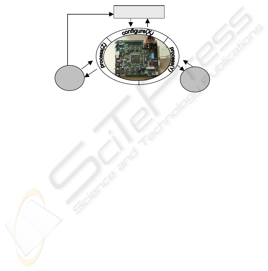
face, etc. – could be abstracted. In such approach, all the subsystems communicating
with the FPGA modules can call a configuration method to set up the desired func-
tionality, and then call methods to pass the data to be processed and receive the re-
sults. Figure 1 depicts such possibility.
configuration bank
sub
system
A
sub
system
B
Fig. 1. Diagrammatic representation of an FPGA board encapsulated by methods to change its
configuration and process data.
In the following section, we describe the technical details on how this approach was
implemented.
3 Loosely-coupled network of FPGA prototyping boards
Several design decisions were taken in order to implement the proposed concepts.
The first of them regarded the underlying network infrastructure over which the ob-
jects should communicate. As TCP/IP networks are nowadays the de facto standard
for the intercommunication of computer systems, this was not much of a choice. By
using TCP/IP as underlying infrastructure, the deployment of FPGA modules can be
done over any Internet-like network.
The following decision regarded the implementation of the infrastructure allowing
distributed access to the FPGA modules. In our approach, we consider a module to be
accessible if a student or designer is able to use it no matter where it is located or
which kind of FPGA devices it has. It is also desirable that the infrastructure allows
the FPGA module to be included, moved or and excluded dynamically within the
distributed system, aiming to more flexibility and fault tolerance.
There are some middleware solutions which can fulfill those needs, such as
CORBA [5], Jini [6] and UPnP [7]. All of them work over TCP/IP networks, and
3
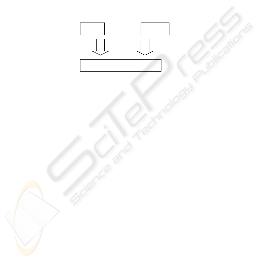
share the common architecture showed on Figure 2. In principle, any of them could
be used to support our approach.
Our implementation uses Jini, mainly because of the freely available development
tools and because most of the facilities for service lookup, discovery and join are
already implemented and freely available. Jini also includes a programming model -
built over the Java language framework - covering leases, events and transactions.
The remote method invocation infrastructure also rely on Java language features,
specifically on the JavaRMI package. Such programming model uses local proxies to
reference remote objects, so in the application domain all method calls seem to be
local, reducing the overhead usually associated to dealing with remote subsystems.
serviceclient
advertises
service
queries for
service
middleware
leased
service
attributes
Fig. 2. Middleware architecture, where service providers can advertise services and clients can
query for services matching given criteria.
The procedure a student/designer goes through in order to access the FPGA module is
described in the UML sequence diagram in Figure 3. Initially, the user’s client mod-
ule searches for a lookup service. If the network address of the lookup server is
known, a direct connection is established. Otherwise, an UDP multicast request can
be sent, which would be replied by the lookup servers reached by the request.
When the connection with the lookup server is established, the client module
should perform the service lookup. Such lookup is usually done based on a key which
provides unique identification of the service. In our implementation, such key would
identify the desired configuration for the FPGA module. By using Jini, we also have
the possibility of using an object as a key, so a more sophisticated lookup can be
done. It allows a scenario where the client is able to provide a specific configuration
as a key. In such case, the lookup server can use the attributes of this configuration
(target device, logical capacity, etc.) to find an available FPGA module which
matches the request. In Figure 3, however, the general case is depicted, when the
configurations are all pre-stored in a configuration bank (in our implementation, a
special Jini service called JavaSpaces [8] is being used to store the configurations).
By relying in such approach, the client can access an FPGA module in a com-
pletely transparent way. Its location - as well as the location of the lookup server - are
dynamically obtained during runtime and are transparent for the client developer. The
internal functionality of the FPGA module is also hidden, since the client access it
through a proxy object. The interface of such proxy object - the API calls it support -
are the only information the client requires in development time.
4
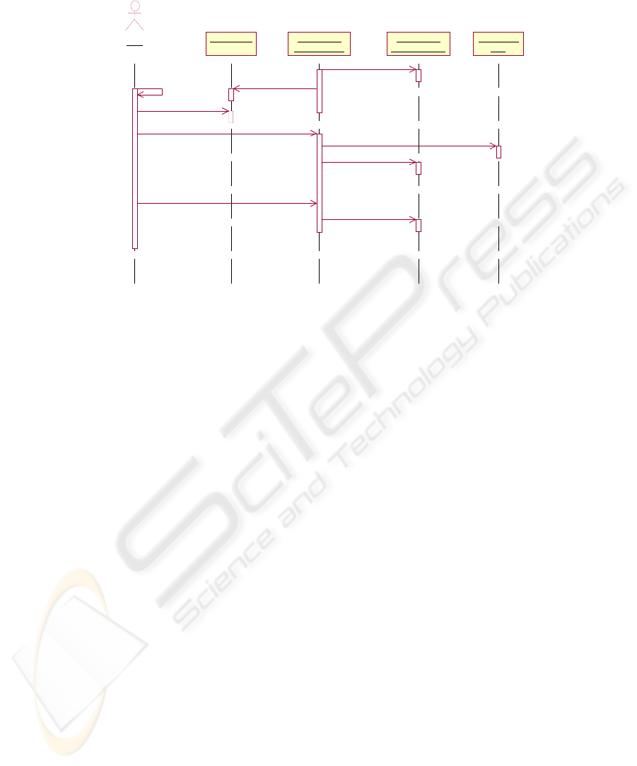
lookup service
client
reconfigurable
hardware s ervice
reconfigurable
hardware back end
configuration
bank
create( )
registerService( )discoverLookup( )
lookupService( )
configure( )
getConfiguration( )
configure( )
process( )
process( )
Fig. 3. UML Sequence diagram depicting the procedure for the remote access of FPGA mod-
ules.
In order to map the API calls into specific functions - which are usually particular for
each type of FPGA platform - we use a backend module in the host computer in
which the FPGA board is connected. Such backend is developed specifically for a
single type of FPGA board and handles the platform-dependent functionality - e.g.
setting up for configuration, accessing memory modules, etc. Our implementation
was done in a XESS XCV-800 Virtex Board, so we implemented a specific backend
API for it, encapsulating on it the functionality to program the FPGA and access the
SRAM memory banks.
Another problem which must be solved in the backend module is the data abstrac-
tion support. While in the object-oriented domain all the computation is based in
complex data types, when it comes to hardware such data types should be processed
at the bit level. In order to make the bit level computation invisible from the object-
oriented domain, we provide a data conversion interface API, which can be used with
small updates in a wide range of FPGAs. Such interface organize the data to be proc-
essed by the FPGA in a bit array, including in such array the information about the
data types. The array is uploaded to the prototyping board memory, where the FPGA
reads, it, processes it and write the results back so the backend can do the inverse
operation and send the results back to the object domain
In order to facilitate the development of hardware configurations supporting our
approach, we provide an HDL description of a module which is able to read the data
array assembled by the backend module and reconstruct it as data types which are
tractable within the HDL domain. The inverse path is of course implemented, so that
the results of the data processing done by the FPGA can be written into the memory
in such a way the backend module can rebuild into data types.
5

This type abstraction module should be built on top of the memory interface mod-
ule (in our implementation we use the XESS memory interface developed by [9]). By
using such module, the students/designers can focus on the FPGA functionality,
without particular care to the fact that the processor will be encapsulated and inte-
grated into a distributed objects environment. Figure 4 depicts the layered architec-
ture we provided to grant the complete separation between domains.
backend
int
float
int[ ]
10101110101
01110101010
10101010101
00101010101
01001010101
01010010010
10100111001
01010101001
memory
hardware design
memory interface
type abstraction
std_logic_vector
bit_vector
object domain
hardware domain
Fig. 4. Abstraction layers to application development and hardware design.
4 Remote Laboratory of FPGA-based Design
The approach described in the previous sections was put into practice on the imple-
mentation of a virtual laboratory for FPGA design. Such laboratory uses the proxy-
based encapsulation of FPGA boards and the lookup server features to grant lab users
an efficient and straightforward access to a number of FPGA boards. Our implemen-
tation was targeted to students in an educational laboratory, but such infrastructure
can be easily reused to support groups of designers in an industrial environment.
The usual lab session starts by the design of the FPGA configuration. Such con-
figuration can be directly specified by the students using logic schematics (for low
complexity designs) or hardware description languages such as VHDL. Typical ex-
amples of such configurations can range from simple counters controlling seven-
segment displays and LEDs to complex audio and video processing algorithms. If the
pedagogic goal does not include the actual design of the hardware configuration – for
instance, if the lab targets vocational students who will work mainly on the imple-
mentation of previously designed systems – there is the possibility of using pre-
designed IP cores such as those found at [10]. In such cases, the students would work
with the pre-designed models as black boxes, incorporating to them the interface to
access the memory models of the FPGA board mentioned in the previous section.
Several design automation tools must be used during the specification, validation
and generation of the hardware configuration file, such as simulators and tools for
synthesis, placement and routing. Such tools may be available locally at the student’s
workstation or at a remote server, as described in detail in [3]. Once the configuration
file is generated, it can be uploaded to the JavaSpaces service and made available to
all suitable FPGA boards.
6
To validate the design together with an FPGA board, the user accesses the lookup
server and queries for boards which are available and have the possibility to imple-
ment the uploaded design . If are there boards available, the user downloads a proxy
and uses the proxy interface to configure the board with the desired configuration file,
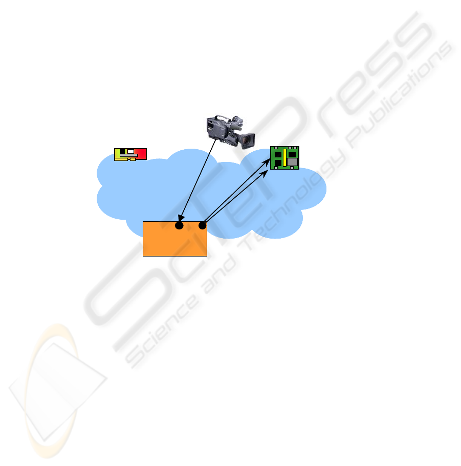
and then to send test data to be processed by the configured FPGA device. Figure 5
shows this procedure and Figure 6 shows the actual implementation of one FPGA
board server. Graphical user interfaces are provided to the user, simplifying the up-
load of the configuration file, the lookup of the boards and the transmission and re-
ception of test data. As the APIs for such tasks are well defined, other tools and more
powerful GUI modules can also be developed and easily integrated. To make the
validation richer, we also allow the user to take advantage on visual features that may
be available at the FPGA board, such as seven-segment displays, LEDs, etc. In order
to feed the remote user with the visual aspect of the board, we included a digital cam-
era which can provide either video or still pictures from the board. Figure 7 is a snap-
shot of an user’s screen showing the video feed coming from the remote FPGA
board.
Network
FPGA Board B
student
process
configure
FPGA Board A
image/video
NetworkNetworkNetwork
FPGA Board BFPGA Board B
student
processprocess
configureconfigure
FPGA Board AFPGA Board A
image/videoimage/video
Fig. 5. Remote laboratory for FPGA-based design. The black circles at the student side repre-
sent the proxies to access the encapsulated FPGA boards.
5 Conclusions and Future Work
This paper presented the technical infrastructure to build efficient access to remote
FPGA boards. Such infrastructure was used to set a remote laboratory for prototyping
digital integrated circuits, allowing more flexibility and efficiency than the previously
reported approaches. The flexibility of the proposed solution can be seen from three
different dimensions: time, because the users don’t have to follow opening hours to
access the lab; space, because the lab can be accessed by any computer connected to
the internet; and platform, because the use of platform independent solutions such as
Java and Jini allows users to access the lab regardless of the operating system on their
computers.
7
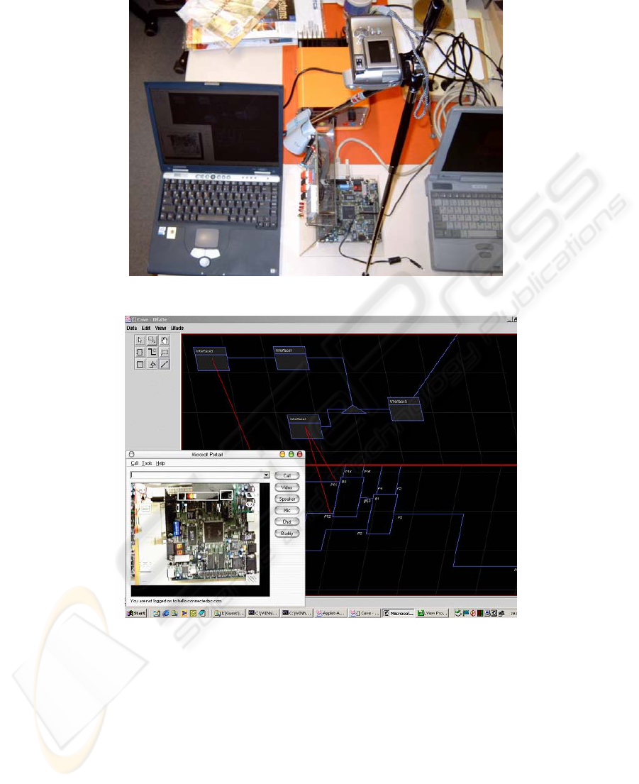
Fig. 6. Remote FPGA server (right), FPGA board (middle) and user client (left).
Fig. 7. User screen snapshot showing FPGA video feed.
Future work will include the integration of the encapsulated FPGA boards within a
simulation environment, allowing the users to validate parts of the system simulation
model with the parts of the system which are already implemented in the FPGA
board. Current efforts are focused on the Ptolemy II framework [11], where the
FPGA board would be modeled as an actor built on top of the implemented proxy-
based encapsulation scheme.
8

References
1. Compton, K., Hauck., S.: Reconfigurable Computing: A Survey of Systems and Software.
ACM Computing Surveys, Vol. 34 (2). ACM Press, New York (2002) 171–210
2. Doss, C. C., Gloster, C.S.: Automated Interface Generation for Remote Access to Adaptive
Computing Resources. In: Military and Aerospace Applications of Programmable Devices
and Technologies Conference (MAPLD), Laurel, Maryland, USA (1999)
3. Becker, J., Mayer, U., Glesner, M., Indrusiak, L. S., Reis, R.: Providing Flexible Internet-
Infrastructure for FPGA-Based CAD Courses. In: Proceedings of the European Workshop
on Microelectronics Education (EWME), Aix en Provence, France (2000)
4. Indrusiak, L. S., Lubitz, F., Reis, R., Glesner, M.: Ubiquitous Access to Reconfigurable
Hardware: Application Scenarios and Implementation Issues. In: Design Automation and
Test in Europe (DATE), Munich, Germany (2003)
5. Object Management Group. Common Object Request Broker Architecture (CORBA). v.
3.0. http://www.omg.org
6. Arnold, K., Wollrath, A., O'Sullivan, B., Scheifler, R., Waldo, J.: The Jini specification.
Addison-Wesley, Reading (1999)
7. Microsoft Corporation. Universal Plug and Play Device Architecture. v. 1.0.
http://www.upnp.org/download/UPnPDA10_20000613.htm
8. Freeman, E., Hupfer, S., Arnold, K.: JavaSpaces: principles, patterns, and pratice. Java
Series. Addison Wesley, Reading (1999)
9. Sutton, P. et. al.: VHDL Interfaces and Example Designs for the XSV board.
http://www.itee.uq.edu.au/~peters/xsvboard/
10. The Free-IP Project. Free-DES. http://www.free-ip.com
11. Lee, E. A., Neuendorffer, S., Wirthlin, M. J.: Actor-Oriented Design of Embedded Hard-
ware and Software Systems. Journal of Circuits, Systems, and Computers, Vol. 12(3).
World Scientific, 231-260 (2003)
9
