
The Database and Architecture of Virtual and Remote
Laboratories: Implementations in the Virtual Electro
Lab Project
Sorin Moraru, Ionuţ Diaconu, Adrian Pelcz, Silviu Leahu
Faculty of Electrical Engineering an Computer Science,
"Transilvania" University of Brasov, Politehnicii street, Brasov,Romania
Abstract. This paper treats the database structure and the architecture of “Vir-
tual ElectroLab”. The “Virtual ElectroLab” makes use of a relational database
(MS SQL). It is also covered the communication procedure between the client
and server. The paper describes the database structure exemplified through the
database diagram. The web-based experiments are executed in an asynchronous
mode.
1 Introduction
A relational database is a collection of data items organized tables from which data
can be accessed or reassembled in many different ways without having to reorganize
the database tables.
The standard user and application program interface to a relational database is the
structured query language (SQL). SQL statements are used both for interactive que-
ries for information from a relational database and for gathering data for reports.
In addition to being relatively easy to create and access, a relational database has
the important advantage of being easy to extend. After the original database creation,
a new data category can be added without requiring that all existing applications be
modified.
A relational database is a set of tables containing data fitted into predefined catego-
ries.
Each table (which is sometimes called a relation) contains one or more data cate-
gories in columns.
Each row contains a unique instance of data for the categories defined by the col-
umns. For example, a typical business order entry database would include a table that
described a customer with columns for name, address, phone number, and so forth.
Another table would describe an order: product, customer, date, sales price, and so
forth. A user of the database could obtain a view of the database that fitted the user's
needs. For example, a branch office manager might like a view or report on all cus-
tomers that had bought products after a certain date. A financial services manager in
the same company could, from the same tables, obtain a report on accounts that
needed to be paid.
Moraru S., Diaconu I., Pelcz A. and Leahu S. (2004).
The Database and Architecture of Virtual and Remote Laboratories: Implementations in the Virtual Electro Lab Project.
In Proceedings of the First International Workshop on e-Learning and Virtual and Remote Laboratories, pages 38-43
DOI: 10.5220/0001151600380043
Copyright
c
SciTePress
The definition of a relational database results in a table of metadata or formal de-
scriptions of the tables, columns, domains, and constraints. [2]
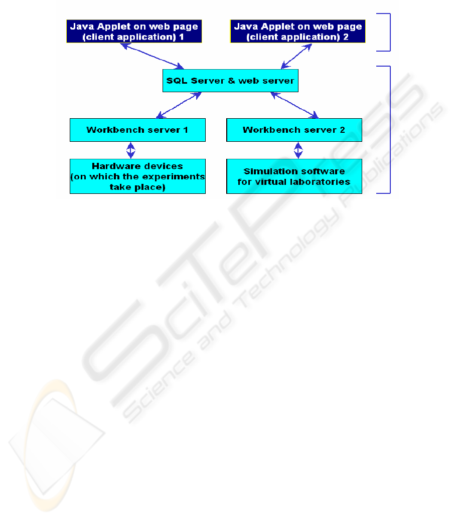
Fig. 1. Virtual Lab architecture.
2 Architecture
The current architecture for the Virtual Lab is presented in figure 1. The Java applet
is the client side (front-end) for the virtual laboratory and it contains the user inter-
face. Its role is to allow the user to send requests to execute requests and to show the
results of these experiments to the user.
The SQL and web server, the workbench servers and the hardware devices will be
treated from now on as Virtual Laboratory Server (VLS).
The visible part of the VLS is the SQL server, together with the web server. To
this part will be sent the requests and from here will be read the responses. It is re-
sponsible for managing the experiment requests and the experiment results.
So, a request will be sent to the VLS and the response will be read from the VLS,
independent of the nature of laboratory underneath the SQL and web server layer.
Considering these, we may see the architecture as a two-tier one. The client side is
the Java applet and the server side is the VLS.
This architecture is integrated with the Learning Management System (LMS)
37
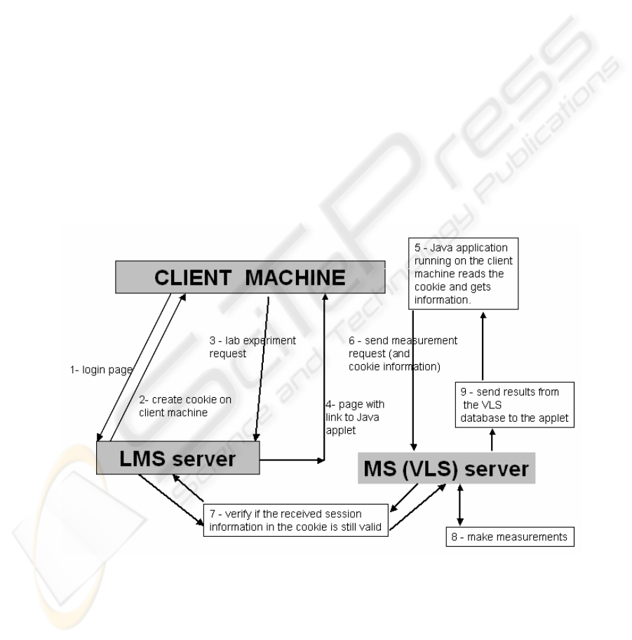
3 Communication procedure
The Communication procedure is presented in figure 2. The login page is provided by
the LMS. The user is prompted for authentication before accessing the LMS.
If the login is successful, on the client’s computer a cookie, containing the user
name, session ID and other information is created.
After the user has acknowledged the material in the course, the LMS will show a
link button to the remote laboratory page. The user clicks this link
The LMS “knows” where to find the laboratory page and opens it. The laboratory
page is found on the VLS and it contains the Java Applet that the user will see.
The user needs to have the Java Runtime Environment installed. If so, the Java vir-
tual machine will start and run the applet. The first thing the applet does is reading the
information stored in the cookie (step 2). After all the initialization is done, the user
will be able to use the applet for creating requests.
The user sends a request to the VLS (the location that provided the physical page
and the applet classes) for measuring. This request also contains the information
stored in the cookie. So, the VLS can check for validity.
The VLS sends the cookie information to the LMS. The LMS checks if the session
is still valid and sends the verification result back to the VLS.
If the check at step 7 was successful (the LMS returned OK), the VLS will make
the measurements and generate the results.
Fig. 2. Virtual Lab architecture.
38
The measurement results are stored in the VLS database and are sent immediately to
the Java Applet running at the user, if the mode is 2, or sent when requested if the
mode is 1.
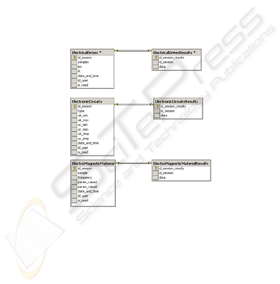
4 Database structure
The figure 3 illustrates the structure of the three tables associated with the three al-
ready finished remote laboratories.
The tables on the left hold the measurement requests, and their structure differs
from one laboratory to another.
The tables on the right hold measurement responses and for each table in the left,
there is a corresponding table on the right.
Fig. 3. Database structure.
For each record in the left table there is one corresponding record (with the same id
and id_session) in the right table for a solved request and for unsolved requests, there
is no corresponding record. This record (response) is created by an application, which
does the actual data measuring.
39
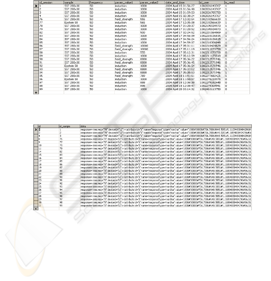
5 Asynchronous web based experiments
Figure 4 presents a snapshot with example records from the requests table for the
“Electromagnetic materials” laboratory.
Figure 5 presents a snapshot with example records from the responses table for the
“Electromagnetic materials” laboratory.
Fig. 4. Requests table for the “Electromagnetic materials” laboratory.
Fig. 5. Responses table for the “Electromagnetic materials” laboratory.
In order to split the synchronous functionality into three asynchronous steps, our Web
Page Team has developed a more complex system, which includes the SQL Server as
database.
Now, the web experiment goes through the following steps:
When the user posts a request, this is stored into the database table, which corre-
sponds to that laboratory. From there, the application that executes the physical meas-
40

urement takes the request, gets the experimental data from the hardware equipment
and places the measuring results into another table in the database as a new record,
corresponding to the request solved.
The user can look anytime at the posted requests for a certain laboratory, because
they are stored into the database. Also, the user will see which request has been
solved and which not.
When a user wants to see the graphic results for a certain solved request, these will
be retrieved from the corresponding database table (from where the results were
posted by the application that made the measurements).
6 CONCLUSIONS
The asynchronous experiments approach brings the great advantage. This is the pos-
sibility to post measurement requests and see the results at a later time, without the
need to wait online for the results.
Another advantage of this system is that it stores all the measurement values for
different parameter configurations. Like this, when a student posts a request for an
experiment that was already done by another student, the experiment’s results will be
taken from the database instead of executing the redundant laboratory test again.
The system’s architecture is based on three functional levels (client – server –
laboratory software (workbench server)).
REFERENCES
1. Louis, R., 1999. Software agents’ activities. In ICEIS’99, 1st International Conference on
Enterprise Information Systems. ICEIS Press.
2. Taylor, A., 1997. JDBC Developer’s Resource, Informix Press.
3. Smith, J., 1998. The book, The publishing company. London, 2
nd
edition.
41
