
An Environment for Remote Control
Paulo Almeida, Fernando Coito, Luís Palma
Departamento de Engenharia Electrotécnica, Faculdade de Ciências e Tecnologia
Universidade Nova de Lisboa, Monte d
e Caparica, 2829-516, Portugal
Abstract. This paper presents an environment for monitoring and control of
rem
ote systems. The aim of this work is the development of software for virtual
laboratories, and e-learning. The architecture based on a server and multiple
clients, runs on a LabView® platform. Remote clients can monitor and control
remote process models or real systems linked to the server, via the TCP/IP
protocol. The Environment for Remote Control (ERC system), under
development, is appropriate for control education and allows the use of
different type of controllers, such as PID, Fuzzy, and others, implemented in the
Matlab® language.
1 Introduction
Since the beginning of the Internet there was been steady development of
technologies for Internet-enabled instrumentation. Remote process monitoring was
the first type of application in networked instrumentation. However, the remote
control technologies attract most interest in both industry and academic institutions.
Laboratory experimentation is a very important part of the curriculum of many
engi
neering courses. The price of instruments and experimental equipment is very
expensive. In most university laboratories does not exist the desirable number of
equipments. For this reason, laboratory in the most time are full or restrict [1], [2].
Work in a real laboratory imposes time and physical boundaries both for students
and for acade
mic staff. It requires significant scheduling effort and financial
investments. Lately, universities are strongly advocating for the introduction of
modern education technologies, and the option of online delivery of courses both for
internal and external students [3].
The proposed ERC system implemented based on the LabView platform, presented
in
this paper, allows the implementation of client-server architecture for real and
virtual laboratories [4]. A real physical system or a process model can be remotely
control from a personal computer (PC) via the Internet using virtual instruments. The
system allows experimental data to be collect and transfer to the remote user for
further analysis. The user would then be able to view experimental results and
analysis outcomes on a computer screen, display the results on the screen, or submit
the results in electronic form for assessment.
Almeida P., Coito F. and Palma L. (2004).
An Environment for Remote Control.
In Proceedings of the First International Workshop on e-Learning and Virtual and Remote Laboratories, pages 160-166
DOI: 10.5220/0001151801600166
Copyright
c
SciTePress
This kind of remote control systems can be build using other technologies, such
Common Gateway Interface-CGI, JavaScript or Active Server Pages – ASP using a
HTML browser for a simple interface. The complexity of the controllers need a
technology based on measurements and controls. The LabView software, from
National Instruments, which support the TCP/IP protocol and the integration of
Matlab scripts, is a powerful tool for control techniques [4], [5].
2 ARCHITECTURES OF ERC SYSTEM
In this section, are present the hardware, the server, and the client architectures of the
proposed ERC system. All these architectures are implementing based on the
LabView.
2.1 Hardware Architecture
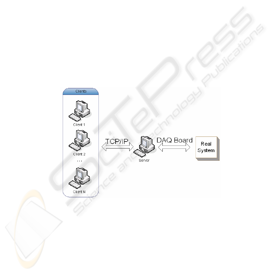
Figure 1 shows the hardware architecture. The server is link to a real process with a
DAQ board. The DAQ board interfaces to the real industrial processes and laboratory
equipments.
Fig. 1. Hardware architecture.
Both Server and Clients have links to the Internet via the TCP/IP protocol. They
communicate between them, changing information (variables, time, process features,
etc). The base of this system is the LabView, which have the TCP/IP protocol
implemented.
The server runs independently of the clients and can supervise all of them.
Through a data acquisition board (DAQ), the server can collect all real system data.
Instead of the real system, the server can simulate a model.
159
Each client has a limited time attributed by the server to run the several control
tasks. The main tasks are: a) define the reference signal (set-point to the controller); b)
tune the controller; c) upload the code of a new controller; d) test the algorithms.
The clients can visualize the results of the experiment on the local screen. The
ERC system has a user-friendly interface, which is very easy to use.
2.2 Server Architecture
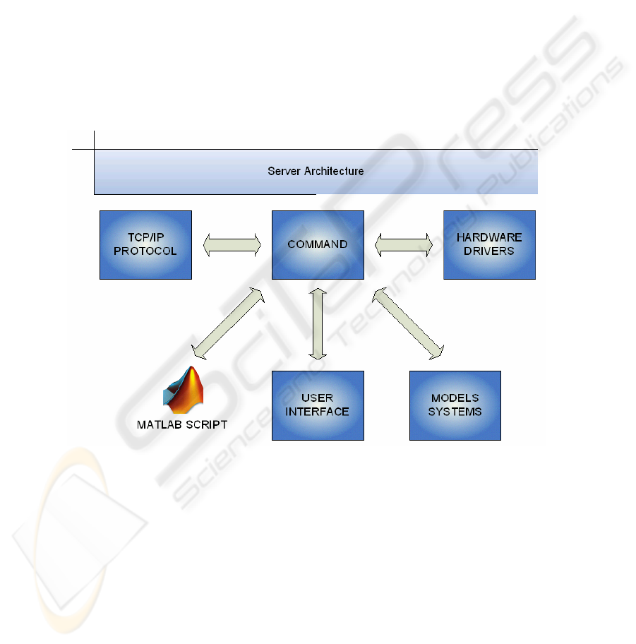
The server architecture is depicting in Figure.2. The LabView software implements
the communication protocol and hardware drivers. Via an interface, the user of the
server can visualize the different signals, monitor the client’s activity, and control
their activities [6]. The real process or the simulation models are test by the client, but
when the server user wants it can pass to the front of client list.
Fig. 2. Server architecture.
A model build in the server can simulate the real system.Controllers can be
implementing on the Server or on the Clients. Through Matlab scripts, the user can
implement its proper controller, or runs the controllers previously implemented on the
server. The Matlab scripts are implemented in M-File editor for better easiness
implementation and need to be a regulated file with several variables. These scripts
are upload for Labview code, in the client or in the server PC.
160

A supervisor controls the time allow for each active client, putting their in a list by
order of entry. The server controls the process or model. When a client connects, the
process control can be passed to the client.
2.3 Client Architecture
The client architecture is very similar to the server architecture. However, the client
works with Matlab. The interface is build in that tool and calls another interface made
in Labview tool. This interface can run a controller on the server; the controller can be
one of the available on the server, or a new algorithm (Matlab script) uploaded.
Nevertheless, it also run an owner controller implemented in the client tool.
Fig. 3. Client architecture.
The experimental results are saved in a MAT file; this file saves variables with system
information (process model, times, controllers gain, etc). The user has a limited time
supplied by server supervisor to use the real system, or process model. If the user
connected to the server has no activity, the server can disconnect and connect another
client in the waiting list. The ERC system allows users to visualize the results of
others active users, but not their MAT file with controller and process parameters.
3 Experimental Results
In this section, since the ERC system is under development, only some preliminary
results are present. Some experiments were done in order to test the performance of
161
the ERC system. Remote monitoring and control algorithms were implemented and
tested.
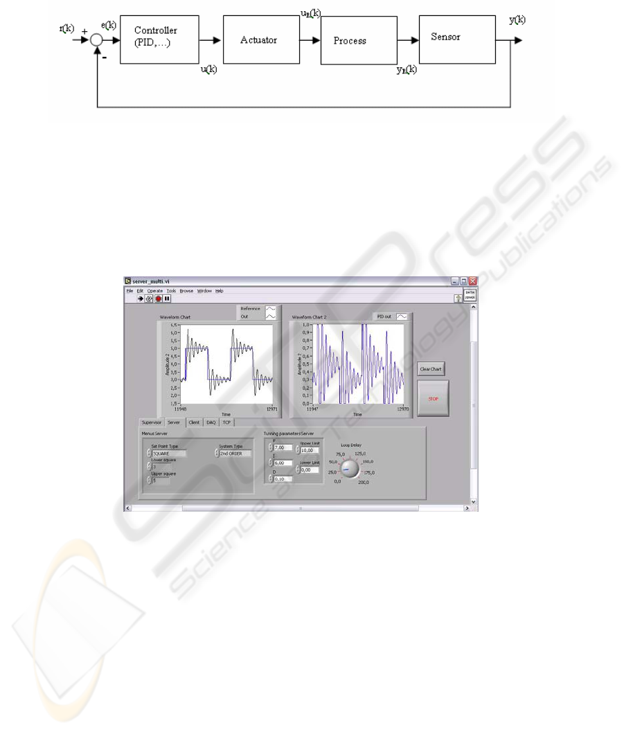
Fig. 4. System control closed-loop architecture.
Figure 4 shows the general architecture of a closed-loop control system. The different
systems (controller, actuator, process, and sensor) are show, as the many signals. The
main signals are: the reference signal r(k), the control error e(k), the input u(k), and
the output y(k). The results presented in this section (figure 5 and figure 6) are due to
the PID control of a second order system [7].
Fig. 5. Server interface.
In Figure 5, is depicted one of the interfaces running on the server PC. As can be
observed, are shown the reference signal r(k) (square wave) and the output signal y(k)
of a second order system. In this interface, the user can tune the parameters (Kp, Ki,
Kd) of the PID control, and the reference signal r(k). The server interfaces change
according the type of controller in use.
A supervision algorithm running on server allows the execution of different tasks:
a) monitoring all the connected clients; b) shutdown one client; c) run the real system,
or the process model.
162
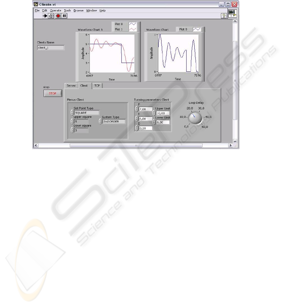
In the client interface, the parameters of controllers implemented on the server are
available, as are in server interface. In both interfaces, is possible to implement new
controllers using Matlab scripts.
Fig. 6. Client interface.
Figure 6 represents the client user interface in Labview platform. As referred, the user
can work with the process or model implemented. After the client use the process, he
can use the data extracted from the experiments to implement the control algorithms.
4 Conclusions
An environment (ERC) for monitoring and control of remote systems is proposed and
described in this paper. The ERC system is appropriate to be use in virtual
laboratories and e-learning platforms.
The proposed ERC system, implemented on a Labview platform, runs on client-
server architecture. The remote clients can monitor and control, via TCP/IP, process
models or real systems linked to the server. Only one of the clients can control, in
real-time, the remote system during a pre-determined time duration.
163

Monitoring and PID control algorithms were implemented and tested, and shown
good performance.
The future work relates to the development of new process models, new control
algorithms, and the improvement of the interface capabilities.
References
1. Astrom, K. and Hägglund, T.: PID controllers: theory, design and tuning. Instrument Society
of America, 2nd edition (1995)
2. AT&T Laboratories Cambridge: Virtual Network Computing [Computer software and
manual]. Retrieved September 17, (2002), from http://www.uk.research.att.com/vnc/
3. Gonçalves, M., Viegas, N., Palma, L.: Sistema de Instrumentação Virtual Concorrente e
Distribuído. In VI Jornadas Luso-Espanholas de Engenharia Electrotécnica, Lisboa-Portugal
(1999)
4. Hopp, C., S. Stoll, U. Konirgorski: Remote Control Design and Implementation using the
Internet, (2002) from http://www.iei.tu-clausthal.de/papers/st_2002_2
5. Reske, D., Moussavi, Z.: Design of a web-based remote heart-monitoring system,
Proceedings of the Second Joint EMBS/BMES Conference, Houston, USA (2002)
6. Travis, J., Internet Applications in LabVIEW, Upper Saddle River, NJ: Prentice Hall, (2000),
28-52
7. Ziegler, J. and Nichols, N.B.: Optimum settings for automatic controllers. Transactions of
the ASME, (1942), 64:759–768
164
