
Implementation of a remote and virtual laboratory
in the field of home appliance systems
Paul Nicolae Borza
1
, Gheorghe Scutaru
1
, Luís Gomes
2
, Anikó Costa
2
,
Lazar Laszlo
3
1
Transilvania University of Brasov b-dul Eroilor29,
Brasov, Romania
2
UNINOVA / Universidade Nova de Lisboa
Faculdade de Ciências e Tecnologia - Campus de Caparica,
2829-516 Caparica, Portugal
3
Siemens PSE Brasov,str. Universitatii 1,C16
Brasov ,Romania
Abstract. One of the most dynamic branches of educational systems is linked
with e-learning. In engineering, experiments play an important role in the learn-
ing process and, in general, impose student’s presence in laboratory in order to
allow them to interact directly with instruments and objects under test. The pa-
per presents some practical examples on how is possible to replace the tradi-
tional laboratory with a remote and virtual laboratory in the field of home ap-
pliance systems. The remote laboratory is based on two dedicated systems
(named DomoControl128 and TinyDomots). Structure, main features and op-
erational principles of current implementations are briefly presented.
1 Introduction
The VIRTUAL-ELECTRO-LAB - “Using information and communication technolo-
gies in development of virtual and remote laboratories for initial and continuous edu-
cation oriented on efficient professional (re)insertion in electrical domain” project
received the support of the Leonardo da Vinci Program from the European Commu-
nity. In the project’s title, main goals are referred. E-learning plays a central role.
Advantages and disadvantages of e-learning systems in general are well known. In
part
i
cular, for the field of electrical and computer engineering, it is very important to
develop the practical skills; in this sense, usage of e-learning environments comple-
mented with remote laboratories can have a significant impact in the student’s learn-
ing rate.
Considering the VIRTUAL-ELECTRO-LAB project,
one
of the areas where it was
foreseen to apply the developed methodologies and tools around the virtual and re-
mote laboratory concept was in the area of home appliance systems (“domotics”).
A specific Learning Management System was developed within the VIRTUAL-
ELECTRO-LAB
project, considering the resources of virtual and rem
ote laboratories.
Nicolae Borza P., Scutaru G., Gomes L., Costa A. and Laszlo L. (2004).
Implementation of a remote and virtual laboratory in the field of home appliance systems.
In Proceedings of the First International Workshop on e-Learning and Virtual and Remote Laboratories, pages 60-68
DOI: 10.5220/0001152300600068
Copyright
c
SciTePress
Our laboratory represents a specific support for the domotics course, where some of
the main functionalities of a home appliance system can be exercised.
Considering our laboratory as a home appliance system that can be monitorized
remotely, the main improvement (from the point of view of the learning process)
consists in the capability to enable remote reconfiguration and parameterization of
parts of the system. In this sense, the structure of the system includes a set of embed-
ded processors, which can individually be remotely reconfigured and enables the
dynamic changes in system’s functionalities.
2 Starting with the Intelligent Building concept
Remote access to home appliances has been always referred in the literature as a main
feature associated with the concepts of intelligent home and intelligent buildings.
Also, integration of systems commonly used within buildings being supported by
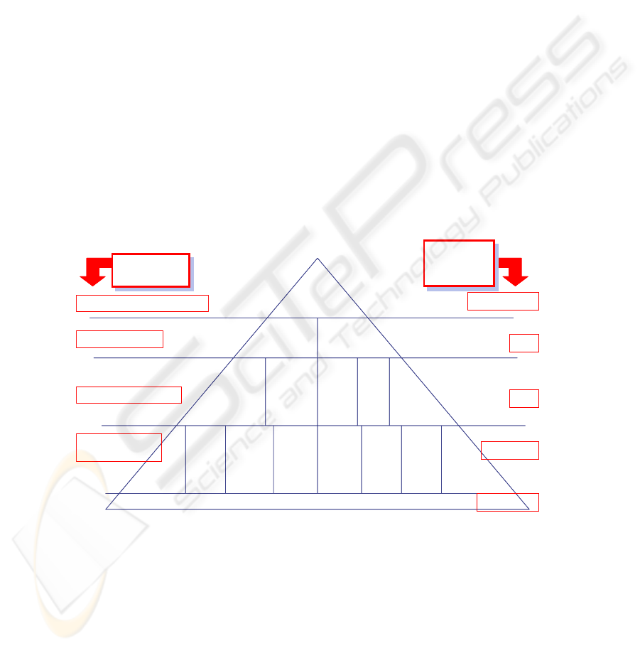
“open protocols” has been always referred as a target. Fig. 1, derived from the views
of the European Intelligent Building Group (EIBG), shows different levels of integra-
tion normally identified within the intelligent building concept (named as “Computer
Integrated Building”). It as to be noted that the timeframes associated with each of the
market development periods have been up-dated along the last decade (in the sense
that the top-level is something to reach in the very near future).
Isolated equipments
Secu-
rity
Access
control
HVAC
Electric
Energy
control,
Lifts,
water, ...
ImageVoice
Data
and
Text
HVAC
and other
Integrated
controls
TV,
Image
Commun.
Voice
Commun.
Text
Commun.
and
Faxes
Data
Commun.
Security
and access
control
Building
Automation
Systems
Integrated
Communication
Systems
Computer
Integrated
Building
XXI Century
90’s
80’s
Early 80’s
Before 80’s
Market
development
periods
Market
development
periods
Integration
Average Level
Integration
Average Level
Computer Integrated Building
Integrated Systems
Multi-functions systems
Dedicated systems/
one-function
Fig. 1. Evolution of the “Computer Integrated Building” concept
Several efforts have been done by companies and academia (some are also under
development). Although, the driving force of such developments has been the indus-
try and market opportunities. This had a severe impact in the evolution of the intelli-
gent building concept implementation, in the sense that most solutions are proprietary
and the open systems and open source strategies have had a limited impact on those
59
home and building systems. Anyway, from the communication protocol infrastructure
point of view, there are several standards available, some of them already approved
inside standardization boards, others approved inside companies’ ad-hoc coalitions as
de-facto standard (where the market is the driving force). Anyway, interoperability of
equipments and systems provided by different companies is limited and a push to-
wards the adoption of open protocols in this area of intelligent homes and intelligent
buildings is welcomed (from the point of view of the user).
From the point of view of the present paper (and of our remote laboratory), only
the left part of Fig. 1 is considered, which means the building automation systems.
3 About the VIRTUAL-ELECTRO-LAB system
The VIRTUAL-ELECTRO-LAB system is an e-learning platform that includes the
access to a set of module courses in the field of electric and computer engineering,
supporting each module through specific virtual and remote laboratories. The e-
learning platform includes a web-site that could be accessed by registered users and
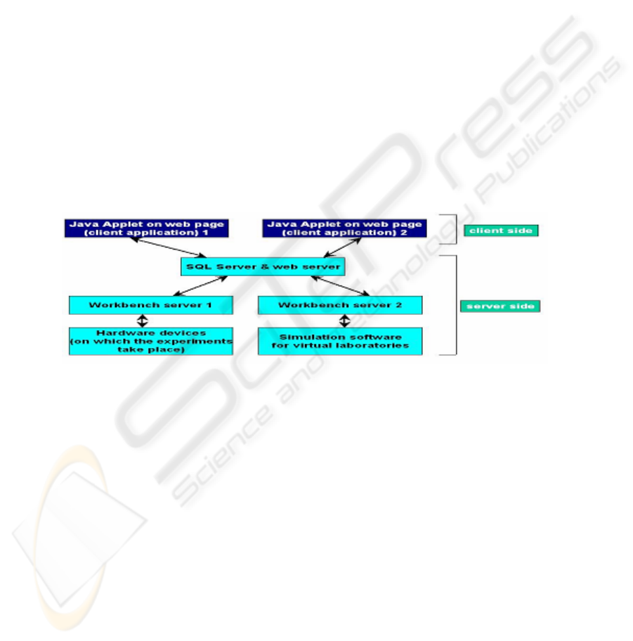
supports experimentation at two levels (see Fig. 2):
- Physical experiment remotely controlled, and
- Remote access to specific simulators associated with specific experiments.
Fig. 2. Structure of the VIRTUAL-ELECTRO-LAB platform
The platform operation is based on the client-server paradigm. The client (user),
after authentication, can access the Web server and associated SQL server capabilities
and issue requests. Relying on the database structure correlated with the workshops,
using the web services, the user could access the remote/virtual laboratory experi-
ments. He can get access to the past experiment results that are archived on database
and could add new experiments by his/her-own. The communication between work-
bench servers and SQL server uses a very flexible xml-based form, which could be
easily adapted for different laboratory types.
60
3 Domotics laboratory
The laboratory is implemented around two different systems: DomoControl128 and
TinyDomot. The two systems can be linked together via a RS-485 bus, although in-
teroperability is limited, at the current stage of implementation. The link with the
server SQL is implemented using a serial line RS-232C through a PC that plays the
role of workbench server.
3.1 The DomoControl128 system
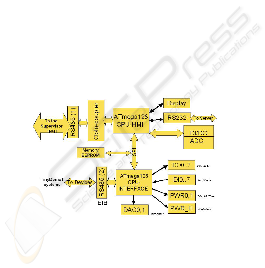
The structure of DomoContro128 system is shown in
Fig. 3. It is based on two AT-
mega128 microcontrollers, interconnected through a SPI link.
One of the microcontrollers, the HMI-controller (on the upper part of the figure),
runs programs that implement specific protocol to assure Virtual-Electro-Lab work-
bench server connectivity, and also the EIB protocol to enable connection for super-
visor level purposes. The SPI interface assures data transfer between the two micro-
controllers and with the EEPROM memory. The HMI-controller will be referred here
by processor 1, and the interface-processor (at the bottom part of the figure) will be
referred here by processor 2.
Fig. 3. Structure of DomoControl128 system
The functions implemented by DomoControl128 system are: acquisition of ana-
logue signals up-to 12 channels with 10-bit resolution, maximum sampling rate
15kS/s; dual channel analogue outputs 12-bit resolution, sampling rate 50KS/s; six-
teen digital input/output channels; four serial interfaces, and more 8 timer/counters.
61
The remote user (a student, for instance) can define the strategy to be used in order
to control the domotics system in the following ways:
1. Writing directly into the flash memory of controller 1 (directly sup-
ported by the use of the microcontroller’s LPM instruction) in order to
change specific parameters to configure the system [2];
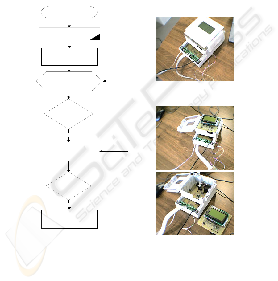
2. Using reprogrammability capability of the processor 2 (that is respon-
sible for the low-level control of system) [3]. Fig. 4 shows the repro-
gramming flow for processor 1 with a new control algorithm or strategy.
Reprogram command
visible for both processors
1 & 2
Delete the current program
on processor 1
Drive the program m ing of
processor 1
Load the loader program
on processor 1
Download in
EEPROM memory of
program from server
for the processor 1
D a ta tra nsm ission
check (downloaded
program )
Download program with errors
Program processor 1 with
the new software
Control the program m ing
phase for processor 1
Download program without error
Test end of
program m ing for
processor 1
Error in program ming
R e start th e
program m ing phase
Restart processor 1 (new
program )
End of program ming
command dedicate for
processor 1
No errors in programm ing phase
Reprogram command
visible for both processors
1 & 2
Delete the current program
on processor 1
Drive the program ming of
processor 1
Load the loader program
on processor 1
Download in
EEPROM memory of
program from server
for the processor 1
D a ta tra nsm ission
check (downloaded
program )
Download program with errors
Program processor 1 with
the new software
Control the program m ing
phase for processor 1
Download program without error
Test end of
program m ing for
processor 1
Error in program ming
R e start th e
program m ing phase
Restart processor 1 (new
program )
End of program ming
command dedicate for
processor 1
No errors in programm ing phase
Fig. 4. Flowchart diagram for reprogramming flash memory of processor and some photos of
the DomoControl128 prototype.
3. Using the resources of a specific operating system installed at the mi-
crocontroller (like microC-OS II, which allows up to 63 simultaneous
62
tasks on the system, and was successfully installed in the ATmega128 mi-
crocontroller system and is currently under configuration). In this case the
management of tasks are more simplified, but with important limitation of
speed.
In current implementation, second option was selected, assuring maximum speed
of program’s execution, but with the penalty of using flash memory more often [4].
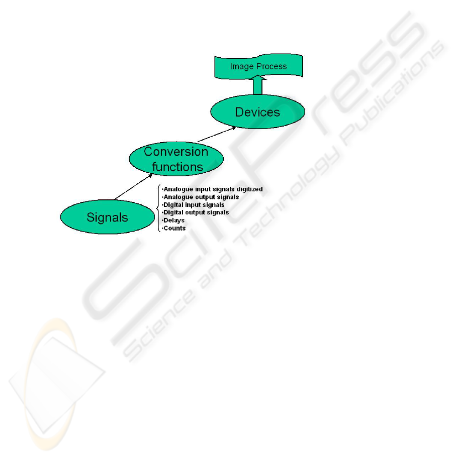
From the point of view of the implementation of the control strategies in the proc-
essor 2, we introduced the “image process”, through the mapping of the actual status
of the input/outputs into the system SRAM memory (see Fig. 5). Moreover, the Plug-
and-Play strategy assure the automatic updating of “image process” when a new mod-
ule is connected to the RS-485 bus, supporting the EIB protocol. When the new de-
vice is registered, it comes into the system with its own data structure too.
Fig. 5. The way from signals to the image process in the DomoControl 128 System
3.2 The TinyDomot system
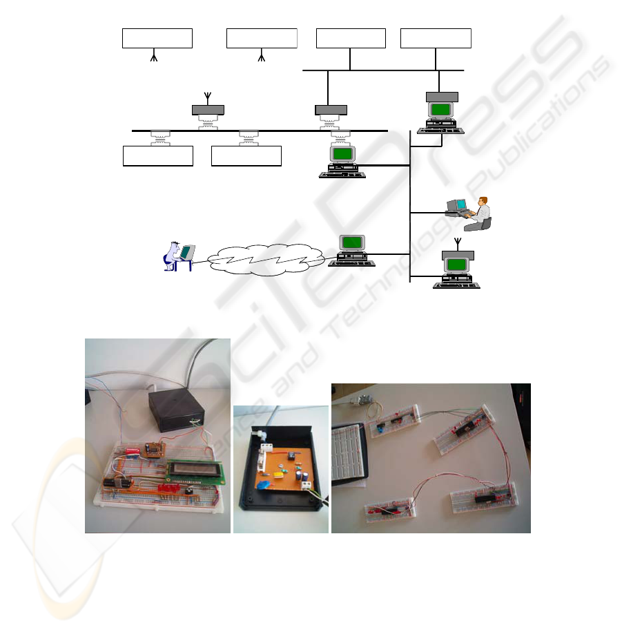
The structure of a network of TinyDomots is shown in Fig. 6 [5]. Each TinyDomot is
developed around a PIC microcontroller (although the port to a different platform
based on the ATmega128 is under way).
Each TinyDomot can have a simplified user interface (keyboard and display),
which can also be reproduced remotely, several inputs from sensors (temperature and
light sensors, presence detectors, and so), and outputs to actuators (lamps, fan, several
equipments), and can be equipped with one network interface. Several communica-
tion supports are possible, from high-speed LAN (Ethernet), to dedicated low-speed
LAN (RS-485), wireless and through the power-line. Specific adaptors making the
bridge between the different sub-networks are available (bridging wireless and
power-line, and so on). All controllers and adaptors were developed using low-cost
micro-controllers, with free-of-charge or low-cost development environments, in
order to allow their usage and replication by a wide number of users.
63
Among the main features of the TinyDomot controller, we can refer to a set of
functionalities targeted to home control and monitoring. As an example, we can refer
to the capability to associated one specific input of one TinyDomot to a set of outputs
in the network; in this sense, we can actuate an input of the TinyDomot located in one
room and switch off the lamps in several locations (if they are switched on), like
garage, hactic, and so, in order to prevent energy’s waste due to forgetfullness. An-
other example is the capability of programming periodic events associated with spe-
cific outputs (like lighting on and off a set of lamps during holiday period to simulate
owner’s presence).
Wireless LAN
Power-line LAN
Dedicated LAN
Internet
Remote access
TinyDomot TinyDomot TinyDomot TinyDomot
TinyDomotTinyDomot
High-speed
LAN
Wireless LAN
Power-line LAN
Dedicated LAN
Internet
Remote access
TinyDomot TinyDomot TinyDomot TinyDomot
TinyDomotTinyDomot
High-speed
LAN
Fig. 6
Topology of the network for home appliances control.
Fig. 7
Some photos of TinyDomot prototypes.
Fig. 7 shows several photos of TinyDomot prototypes, namely the modem power
adapter used in conjunction with a TinyDomot with LCD and in-and out-puts, and a
network of several TinyDomots.
64

4 Didactic aspects
With the set of experiments, we intend to reach different levels of exploitation:
- First level is based on the remote control and monitoring of already available
systems.
- Second level foresees (limited) remote configuration, reconfiguration or/and
reprogramming of specific sub-systems.
Clearly, first level is associated with “regular” users, supporting remote operation
and “play for fun”, while second level supports intermediary and advanced topics
where the users can change configuration (at some extend).
As a first example, we can consider the heating and air-conditioning control sys-
tem:
- At the introductory level, the user can only monitor house variables for every
room (temperature and humidity, for instance);
- At the intermediate level, the user can change the set points and operative
modes (week-days, week-ends, holidays, and so);
- At the advanced level, the user can change everything, even the control algo-
rithm (from a PID controller to a fuzzy controller, for instance), through the
reprogramming of the associated controller.
Afterwards, the user can access to the variable evolution registered in the database
and conclude about the effectiveness of their control strategies. These functionalities
are accomplished through the capabilities offered by the remote and virtual labora-
tory.
As a second example, we consider the access control subsystem. At the first level
(introductory level), the user can remotely monitor the activity of the different access
control controllers (registered entrances and exits). Although, at the second level, one
can change configuration of specific access control sub-systems in several ways, for
instance:
- We can change the users’ database characteristics, namely users and associ-
ated privileges (intermediate level),
- We can change parts or the whole controlling program, as far as the system
supports dynamic reconfigurability (advanced level). This feature will allow
the user to download specific control strategies to the controller. As a spe-
cific example, one can think about a different algorithm to be used for bio-
metrics identification, for instance, through hand-geometry or fingerprint
recognition (just to mention a few).
As a matter of fact, the already referred introductory, intermediate and advanced
levels are concepts already applied to the theoretical part of all the module courses
developed within the VIRTUAL-ELECTRO-LAB, namely to the associated hyper-
text, to allow some guidance to the users according to their expertise, motivations and
goals.
65

5 Conclusions
The paper presents a remote laboratory targeted for remote monitoring and control of
home appliances.
Two dedicated systems were developed (named as DomoControl128 and TinyDo-
mots). Main features of current implementations are briefly presented. Interconnec-
tion between the two systems supporting partial interoperability is foreseen for the
near future.
Exploitation of remote monitoring and remote reprogramming capabilities of the
system can allow users (namely students) to test different control strategies applied to
specific sub-systems within the house or the building.
References
1. E Kayafas, F Sandu I Patiniotakis, P.N. Borza, “Approaches to Programming for Tele-
Measurements”, Proceedings of the XVII World Congres of IMEKO – Lisbon, Lisbon
2001, Selected to be published in a special volume by Elsevier
2. AVR108 : Setup and use of LPM Instruction Atmel Corporation 2002
3. AVR109 : Self Programming, Atmel Corporation 2002
4. AVR105 : Power Efficient High Endurance Parameter Storage in Flash Memory, Atmel
Corporation 2002
5. Luís Gomes, Paul Borza, Anikó Costa; “Home appliance systems and domotics course with
multimedia support”; Proceedings of the 5
th
European Workshop on Microelectronics Edu-
cation – EWME 2004; Lausanne, Switzerland; 15-16 April 2004
66
