
PLANNING TOOL FOR LMDS COVERAGE USING 3D
GEOGRAPHIC INFORMATION SYSTEM DATA
Landaabalo Agba , Laure Freytag , Bernard Jecko
IRCOM (Institut de Recherche en Communications Optiques et Micro-ondes) CNRS UMR n°6615 - équipe "CREAPE"
Faculté des Sciences - 123, Avenue Albert Thomas - 87060 LIMOGES Cedex, FRANCE
Keywords: LMDS, GIS, coverage prediction, Ray Tracing, planning tool
Abstract: Local Multipoint Distribution Services (LMDS) Network operating in 40.5 – 43.5 GHz band in Europe
requires relevant planning tool for its deployment. An accurate knowledge of the propagation environment
(buildings, trees…) is necessary especially in urban areas. This paper presents software based on Ray
Tracing method using 3D Geographic Information System (GIS) database. Several series of simulations
were done and the effects on propagation issues of some parameters were interpreted. Measurements were
also achieved and were compared with simulation curves. Finally, cosecant-squared and switch beam
antennas are briefly presented as solutions to avoid shadowed zones and to improve coverage area.
1 INTRODUCTION
Some years ago, Local Multipoint Distribution
Services (LMDS) is revealed as a real asset to
provide broadband and high capacity access services
to end users. Its deployment needs to develop a
relevant planning tool as it exists for others wireless
systems such as GSM. Furthermore, the assigned
frequency band can be different from a country to
another. To facilitate the design of LMDS network,
we elaborate a computer program based on Ray
Tracing method. This program uses 3D Geographic
Information System (GIS) data.
This paper presents the principles and the
algorithm of the software. The simulation results and
the comparison with measurements are also showed.
Finally, some solutions to enhance and to improve
the coverage area are presented. Cosecant-squared
antenna and switch beam antenna are some of them.
2 A SIMULATION SOFTWARE
PACKAGE
Nowadays the fixed wireless systems such as LMDS
are not to be any more presented. Nevertheless some
advantages are useful to be reminded. These
advantages include the ability to connect with users
in remote areas without laying new cables and the
capacity for broad bandwidth that is not impeded by
fibber or cable capacities. Furthermore, the fixed
wireless networks are easy and fast to be deployed
with incremental infrastructure investment.
Even though, LMDS network is one of the
simplest networks in installation and operation, we
still need to simulate its design to reduce the
installation time and to increase the coverage area by
using the minimum base stations that will reduce the
installation costs and will increase the network
efficiency.
2.1 3D-GIS data with Ray Tracing
method
Geographic information system databases enable
telecommunication professionals to integrate maps
and information to make better decisions. They are
composed by different layers which give geographic
information (where things are) with descriptive
information (what things are) (What is GIS). LMDS
operates at high frequencies (40.5 – 43.5 GHz in
many European countries) for which any physical
obstructions effectively block the signal. GIS data
requirements are therefore based on line-of-sight
parameters.
81
Agba L., Freytag L. and Jecko B. (2004).
PLANNING TOOL FOR LMDS COVERAGE USING 3D GEOGRAPHIC INFORMATION SYSTEM DATA.
In Proceedings of the First International Conference on E-Business and Telecommunication Networks, pages 81-86
DOI: 10.5220/0001381600810086
Copyright
c
SciTePress
t
p
t
r
t
r
A
E
P −=
0
2
2
1
η
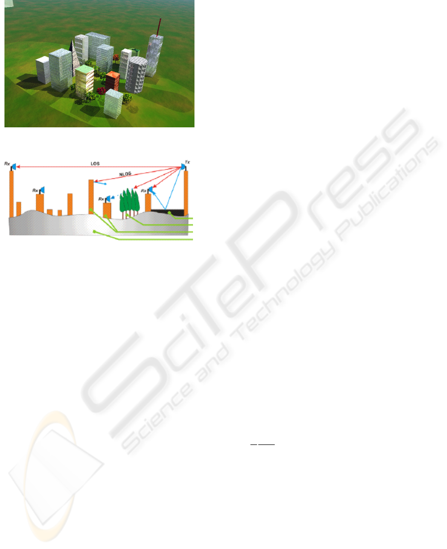
Figure 1: Example of 3D GIS data visualization with
some main layers
To meet these requirements, a virtual metropolis
must be constructed for each city depicting all
buildings and vegetation with a resolution and an
accuracy less than 1 meter. In our case, we use only
some GIS layers that can affect the LMDS link;
these layers are depicted in the figure 1-b.
The building layer is the most important with
two main effects. The direct effect appears when
there are obstacles between the transmitter and the
receiver. The indirect effect is the reflected signal
caused by the construction materials of buildings
(such as: glass, wood, stone, metals...). The building
models must have an incredible level of detail –
elevator shafts, air conditioning ducts, and peaked
roofs are possible obstacles in the design of LMDS
network.
The second important layer is the vegetation
layer that represents the trees areas and forests. This
layer can reduce the quality of service or even
disconnect the LMDS service. Also, we have to
notice that the effect of this layer is seasonal and it
can be changed according to the four seasons of the
year unlike the buildings layer which remains
unchanged all over the year.
Using 3D GIS data can dramatically improve the
reliability and efficiency of a network design. Our
software package makes able to know all effects of
the buildings materials, weather conditions and
terrain textures on the LMDS network, and how
many users will be able to use this network and what
quality of service they will expect.
The computer program is based on Ray Tracing
method (Jensen et al., 1990) stems from Geometrical
Optics (GO) and Uniform Theory of Diffraction
(UTD). It provides several advantages over other
prediction methods
(Rappaport, 1997)
• Precise Signal power level prediction
• Incorporation of 3D pattern of antennas
• Angle of arrival information
• Multipath time delay information
The program traces rays in a digital cityscape.
The total power level is obtained by combining
incident power with reflected power from the sides
of buildings and rooftops across the simulation zone.
2.2 The Simulation Algorithm
The first step is to choose the coverage area and on
this area the optimal location of the base station
(BTS). Then, the Point-to-Region visibility is tested
between the BTS and the subscribers’ out door unit
(ODU) located on households. Two cases are
possible:
• Line-Of-Sight (LOS) areas are
corresponding to 60 % of the potential
single cell coverage area. The reflection
paths are found using method of images
which consists to place iteratively virtual
transmitters behind each surface in
computer 3D database. Each path contains
the same signal with a different time delay.
The total received power is calculated as
follows:
(1)
(2)
Where:
=
t
r
P Total received power
=
t
r
E
Total received field
=
t
p
A Total rain attenuation
=
i
r
E Incident received field
=
rj
r
E
Reflected received field
N = number of reflected rays
=
η
0
Wave impedance
a. Modelling of a 3D environment
V
G
S
B
S = Stree
t
V = Ve
g
etation
B = Buildin
g
s
G = Ground
b. Main GIS layers used in LMDS design
∑
+=
=
N
j
rj
r
i
r
t
r
EEE
1
ICETE 2004 - WIRELESS COMMUNICATION SYSTEMS AND NETWORKS
82
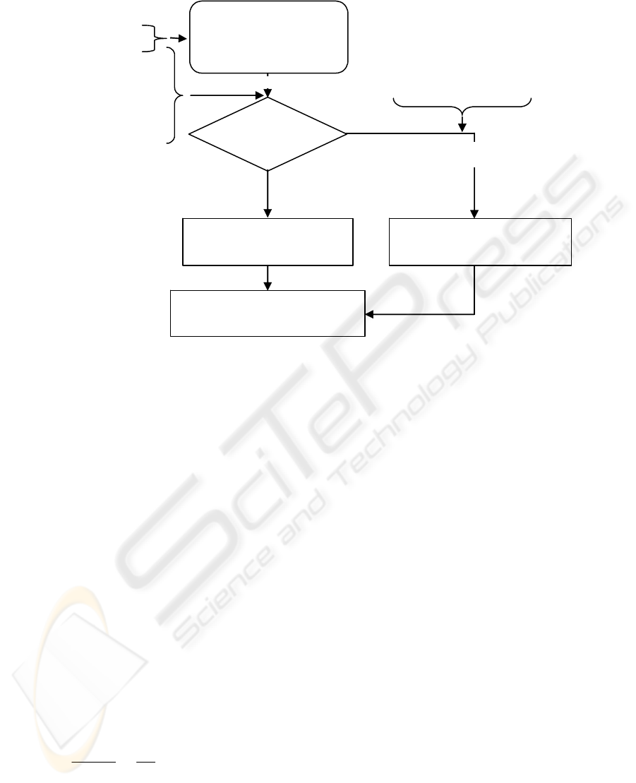
Figure 2: Scheme of LMDS planning tool
The rain attenuation (dB) over a path is given by
relation (3). (ITU-RP 530-7)
(3)
Where:
T is the rain intensity (mm/h), d
eff
is the distance
(km), p is the percentage of connection availability.
The values of k and α are frequency and polarization
dependent factors given in ITU-R
Recommendations. (ITU-RP 838)
•
No Line-Of-Sight (NLOS) or shadowed
areas. The use of reflectors or repeaters will
dramatically reduce these areas and
increase the single cell coverage percentage
to more than 90%. The following formula
(Ruck, 1970) is used to calculate the
received power level which depends on the
passive reflector cross section.
(4)
Where:
Σ = Reflector cross section, its calculation depends
on the geometrical shape of the reflector and the
working frequency.
Pe, Pr = Transmitted and the received powers
Ge, Gr = Transmitted and the received Gains
R
1
= Distance transmitter - reflector
R
2
= Distance reflector - receiver
λ = wavelength
The chart (Figure 2) describes the main steps of
our coverage prediction model. It’s important to
notice that this planning tool can be used for any
other system operating at frequencies above 20 GHz.
The total power level can be depicted as power
curves or power maps. Somme simulation results
with measurements comparison are presented in the
following paragraph.
3 SIMULATION RESULTS AND
MEASUREMENTS
The results obtained using our planning tool allow to
interpret the effects of some parameters on LMDS
network design especially on the coverage
prediction. The figures (3-a, 3-b) show that the
power level is deeply connected in one hand to the
difference of height between the BTS and an ODU
and in the other hand to the weather conditions.
))(log043.00546(
10
12.0
p
effp
pdkTA
+−
••=
α
preer
A
RR
GGPP −
⎟
⎠
⎞
⎜
⎝
⎛
Σ
⎟
⎟
⎠
⎞
⎜
⎜
⎝
⎛
=
ππ
λ
44
2
21
• Transmitter &
receiver parameters
• Weather conditions
• Availability rate
O
p
timization o
f
antennas
p
arameters
O
p
timization o
f
BTS location
BTS site location
Reflector or
Repeater parameters
NO
YES
3D GIS data base &
building materials
characteristics library
LOS coverage using
Ray Tracing Method
Received power level &
estimation of covera
g
e %
Point-to-Region
Visibilit
y
Shadowed areas covered
by reflectors or repeaters
Optimization of reflector or
repeater parameters
PLANNING TOOL FOR LMDS COVERAGE USING 3D GEOGRAPHIC INFORMATION SYSTEM DATA
83
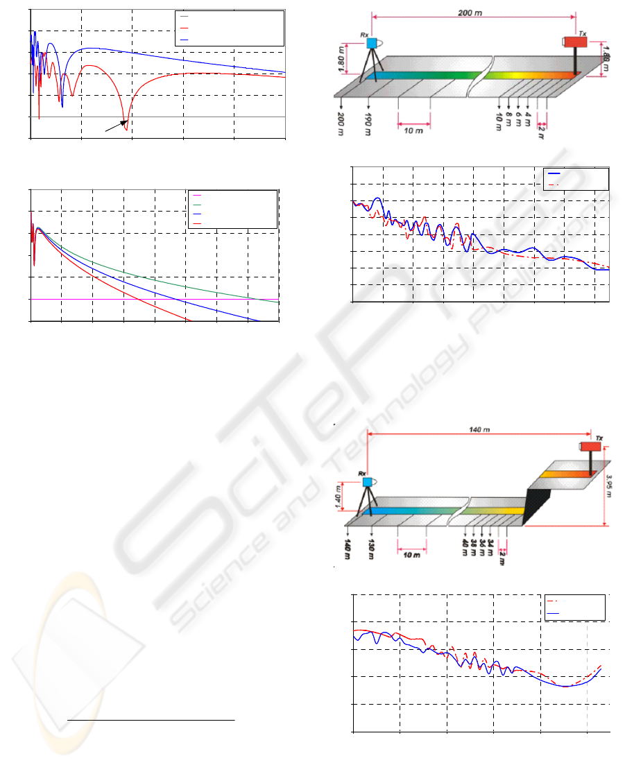
Figure 3: Effects of some parameters on LMDS link
budget
.
The shadowed zone indicated on the
figure 3-a is
only due to the gap between the main lobe and the
side lobes when a directional transmitting antenna in
elevation plane is used. The maximum coverage
range decreases when the intensity of rain increases,
as it is showed on the
figure3-b with 99.99 % of the
availability rate. Some time, the improvement of the
coverage range is possible by a little reduction of
this rate.
On different sites located in Limoges-France,
several series of measurements were achieved using
a Panoramic Field Measuring Device (MCP3000).
The description of measurement conditions and the
comparison of curves are depicted on the following
figures 4-5. The comparison of power levels shows a
good agreement between simulations and
measurements. It is confirmed by the standard
deviation (SD) and the average error percentage of
the two cases presented below.
(5)
With SD = STDEVPA (MS-Excel function)
Error % of measurements: Case n°1 = 8.8%
Error % of measurements: Case n°2 = 3.1%
Figure 4: Measurements achievement: Case n°1
Figure 5: Measurements achievement: Case n°2
We successfully carried out studies of coverage
prediction around ESTER site located in Limoges.
-120
-110
-100
-90
-80
-70
-60
0 100 200 300 400 500
Distance (m)
Power (dB)
Sensitivity threshold = -110 dB
Received power: h = 30 m
Received power: h = 10 m
d
d
Shadowed area
a. Difference of height between antennas
-120
-110
-100
-90
-80
-70
-60
0 500 1000 1500 2000 2500 3000 3500 4000
Distance (m)
Power (dB)
Sensitivity threshold
Rain intensity = 8 mm/h
Rain intensity = 19 mm/h
Rain intensity = 32 mm/h
b. E
ff
ect o
f
rain intensit
y
tsmeasuremenofAverage
SD
Error
__
100
%_
×
=
b. Com
p
arison Simulation-
M
easurements: Case n°1
-90
-85
-80
-75
-70
-65
-60
-55
-50
30 50 70 90 110 130 150 170 190
Distance (m)
Power (dB)
Simulation
Measurements
a. Measurements conditions: Case n°1
b. Com
p
arison Simulation-
M
easurements: Case n°1
-90
-85
-80
-75
-70
-65
-60
-55
-50
30 50 70 90 110 130 150 170 190
Distance (m)
Power (dB)
Simulation
Measurements
a. Measurements conditions: Case n°1a. Measurements conditions: Case n°1
-80
-76
-72
-68
-64
-60
30 50 70 90 110 130
Distance (m)
Power (dB)
Simulation
Measurements
b. Com
p
arison Simulation-
M
easurements: Case n°2
a. Measurements conditions: Case n° 2
-80
-76
-72
-68
-64
-60
30 50 70 90 110 130
Distance (m)
Power (dB)
Simulation
Measurements
b. Com
p
arison Simulation-
M
easurements: Case n°2
a. Measurements conditions: Case n° 2a. Measurements conditions: Case n° 2
ICETE 2004 - WIRELESS COMMUNICATION SYSTEMS AND NETWORKS
84
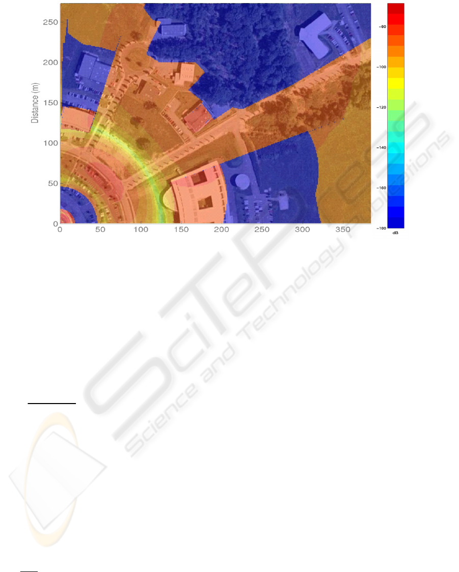
The figure 6 is an example of the power level map with its corresponding coverage area.
Figure 6: Example of coverage with power level map around ESTER site
4 TWO WAYS TO IMPROVE THE
COVERAGE AREA
A solution to overcome the shadowed areas (see
figure 3-a)
is to design a new antenna with cosecant-
squared pattern in elevation plane. (Freytag and
Jecko, 2002) The cosecant-squared diagram is given
by:
(6)
The principle
(figure 7-a) is to compensate the
propagation effect especially in the shadowed areas
near the transmitting antenna of the BTS. At 40
GHz, the coverage area is up to 2 till 3.5 Km from
the base station depending on weather conditions
(see figure 3-b). To increase this range, a switch
beam antenna is designed using Butler matrix 4*4
and its working principle is illustrated on the
figure
7-b
(Dall’omo, 2003). The pointing direction of each
beam is given by:
(7)
Where:
φ
m
= phase gradient between 2 consecutive patches
θ
m
= Angle between the beam m and the normal
direction of the array
d = Distance between 2 patches
λ = Wavelength
The effects on propagation issues of cosecant-
squared and switch beam antenna are respectively
depicted on
figure 7-c and figure 7-d. The shadowed
zones disappear with cosecant-squared antenna and
the coverage area is gone from 50% to 90% by using
switch beam antenna.
5 CONCLUSION
A computer program using Ray Tracing method for
coverage prediction has been implemented based on
3D GIS databases. This planning tool is applied to
LMDS by making several series of simulation in
order to have better understanding of propagation
phenomena in frequencies ranges around 40 GHz.
The comparison between simulations and
measurements was also presented. Finally, the
design of new antennas was carried out to improve
the LMDS coverage area.
Planned on-going research will be focused on
repeaters and will be investigated precisely in the
near future.
()
()
()
0
2
2
sec
sec
θ
θ
θ
Co
Co
G
=
()
mm
Sin
d2
θ
λ
π
ϕ
=
PLANNING TOOL FOR LMDS COVERAGE USING 3D GEOGRAPHIC INFORMATION SYSTEM DATA
85
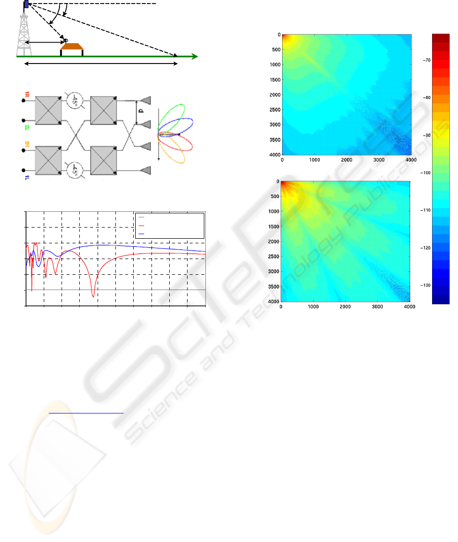
Figure 7: Principle and effect of cosecant-squared & switch beam antennas
REFERENCES
“What is GIS” http://www.GIS.com
Jensen, F., C. Garres & M. Sabbadini, 1990 “CAD
applications with GTD” Journées Internationales de
Nice sur les Antennes, Nice, pp.150-163
Rappaport, T., 1997 “Site-specific propagation” Virginia
Tech
RECOMMENDATION ITU-RP. 530-7, 1992
“Propagation data and prediction methods required
for the design of terrestrial line-of-sight systems” ITU
Radiocommunication Sector, pp.13-17
RECOMMENDATION ITU 838, 1992 “Specific
attenuation model for rain for use in prediction
methods” ITU Radiocommunication Sector, pp.205-
206
Ruck, G.T., 1970 “Radar cross section handbook”
PLENUM PRESS, NEW YORK – LONDON
Freytag, L., Jecko, B., 2002 “Cosecant-squared antenna
for the optimisation of LMDS system coverage”
Journées Internationales de Nice sur les Antennes,
Nice
Dall’omo, C., 2003 “Contribution à l’étude d’antennes à
pointage électronique en millimétrique. Conception et
réalisation de différentes topologies de matrices de
Butler » Thesis of Limoges University
dB
Distance (m)
Distance (m)
Sector based antenna
Distance (m)
Distance (m)
Switch beam antenna
dBdB
Distance (m)
Distance (m)
Sector based antenna
Distance (m)
Distance (m)
Distance (m)
Distance (m)
Sector based antenna
Distance (m)
Distance (m)
Switch beam antenna
Distance (m)
Distance (m)
Distance (m)
Distance (m)
Switch beam antenna
d. Coverage improvement
by switch beam antenna
θ
0
θ
d
max
d
Coverage area
θ
0
θ
d
max
d
Coverage area
a. Principle of cosecant-squared antenna
b. Princi
p
le o
f
s
witch beam antenna
c. Shadowed areas coverage
by cosecant-squared antenna
-120
-110
-100
-90
-80
-70
-60
0 50 100 150 200 250 300 350 400 450 500
Distance (m)
Power (dB)
Sensitivity threshold
Directionnal antenna
Cosecant-squared antenna
ICETE 2004 - WIRELESS COMMUNICATION SYSTEMS AND NETWORKS
86
