
CARE-OF-PREFIX ROUTING FOR MOVING NETWORKS IN
MOBILE IP NETWORK
Toshihiro SUZUKI, Ken IGARASHI, Hiroshi KAWAKAMI, Akira MIURA
NTT DoCoMo, 3-5, Hikarinooka, Yokosuka-shi, Kanagawa, 239-8659 Japan
Keywords: Mobile IP, moving network, routing, addressing, handoff, NEMO
Abstract: The future ubiquitous network will serve so many mobile terminals that it is extremely important to control
them efficiently. One useful approach is to group terminals having similar movement characteristics and
manage them in units of groups. Another important issue is the mobility management of moving networks,
such as a network on a train or in a car, or a personal area network. Moving networks may be defined for a
variety of situations and can lead to a lot of attractive applications. Moving network mobility support is
indeed one of the most interesting research topics. In this paper, we clarify the difference between host
mobility support and the conventional moving network mobility support, propose a mechanism for moving
network mobility support and shows it is better than the conventional ones.
1 INTRODUCTION
Since the future ubiquitous network must serve
several billion Mobile Nodes (MNs) (i.e., mobile
terminals), it is extremely important to control them
efficiently. Given this number of MNs, one key
technique is to group MNs having similar movement
characteristics, and manage them in units of groups.
Another urgent topic is to enhance the mobility
management of local networks, such as a network on
a train, in a car, or a personal area network. This
moving network mobility support and moving
networks can be applied to a variety of situations and
can lead to a lot of attractive applications. This
mobility management is indeed one of the most
interesting research topics today. Many groups
including IETF are actively researching IP routing
techniques to support moving network mobility.
NTT DoCoMo Network Laboratories are also
studying it as a key technology for IP
2
(IP based IMP
Platform) (Yumiba, 2001), a platform we have
proposed for the next-generation mobile network.
The representative requirements for moving
network mobility support in IP are the same as those
for host mobility support (mobility management for
moving hosts rather than a moving network). They
are:
(1) Route optimization
(2) Minimization of the packet header size
(3) Reduction in handoff signal overhead.
“Pinball” Routing (Thubert, 2004), in which
packets are always transmitted via Home Agent
(HA) (Johnson, 2004), cannot satisfy requirement (1)
because it requires excessive network resources.
Given requirement (2), we must minimize packet
overhead by dispensing with encapsulation.
Requirement (3) demands that handoff be achieved
seamlessly with minimal packet loss and short
handoff latency. Therefore, it is important to reduce
the amount of handoff signals. The NEMO WG has
proposed only partial solutions to these three
requirements.
In this paper, we clarify the difference between
host mobility support and the conventional moving
network mobility support, and propose a solution
that satisfies all the requirements. Its effectiveness
was confirmed by using network simulator 2 (called
ns2).
Section 2 briefly describes the difference
between host mobility support and the conventional
moving network mobility support, and the
requirements for moving network mobility support.
Section 3 proposes the basic techniques of a new
routing method applicable to moving networks.
Section 4 introduces a new routing mechanism that
uses these basic techniques for Mobile IP (MIP)
(Johnson, 2004). Section 5 compares the proposed
routing mechanisms with conventional ones.
114
Suzuki T., Igarashi K., Kawakami H. and Miura A. (2004).
CARE-OF-PREFIX ROUTING FOR MOVING NETWORKS IN MOBILE IP NETWORK.
In Proceedings of the First International Conference on E-Business and Telecommunication Networks, pages 114-120
DOI: 10.5220/0001383201140120
Copyright
c
SciTePress

2 DIFFERENCE BETWEEN HOST
MOBILITY SUPPORT AND THE
CONVENTIONAL MOVING
NETWORK MOBILITY
SUPPORT
The characteristics and brief evaluations of NEMO
Basic Support (hereafter referred to as Basic)
(Devarapalli, 2004) and Reverse Routing Header
(RRH) (Thubert, 2004), both of which are currently
proposed in NEMO WG for moving network
mobility support, are shown below.
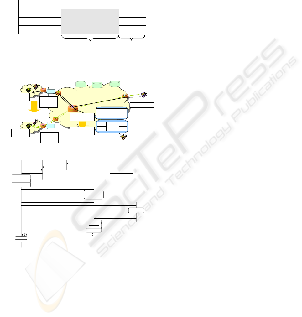
Basic constructs a bidirectional tunnel between a
Mobile Router (MR) and the HA of that MR.
Packets from/to MNs in a moving network are
always carried via this tunnel (Fig. 1). When the
moving network moves, handoff is achieved by
reconstructing a tunnel. Specifically, a bidirectional
tunnel is reconstructed between the Care of Address
(CoA) (Johnson, 2004), which an MR is allocated by
the new AR (Access Router), and the HA address of
the MR. CoAs of MNs in the moving network
remain unchanged even if handoff occurs. This hides
the move of the moving network from the MNs in
the moving network. Furthermore, even if there are
many MNs in the moving network, handoff can be
achieved easily because only this bidirectional tunnel
needs to be reconstructed. Therefore, there is a high
possibility that requirement (3) can be met. However,
the undesirable effect of Pinball Routing is
significant if the HA of the MR is far from the
moving network. Additionally, packet overhead is
greatly increased because packets are doubly
encapsulated, once for the bidirectional tunnel and
another for the CoA of the MN. Therefore, Basic
cannot meet requirements (1) and (2).
RRH satisfies requirement (1) (Fig. 2).
Specifically, routing is optimized as follows. All
CNs are informed of the CoA of the MR, and the
packets destined to MNs in the moving network are
transmitted with Routing Header Option (RHO) in
IPv6 (Deering, 2004). That is, the CoA of the MR
and the CoA of the MN are attached. With regard to
Requirement (2), RRH yields packet header sizes
that lie between those of Basic and host mobility
support. When the moving network moves, it is
necessary to inform all CNs of the change in the
CoA of the MR. The more CNs there are, the more
handoff signals are sent. Therefore, RRH cannot
meet requirement (3).
As mentioned above, neither of the two
conventional mechanisms can satisfy all
requirements. This is due to the assumption made by
NEMO WG for the moving network. NEMO WG
assumes that the prefix inside a moving network, i.e.
Moving Network Prefix (MNP), is fixed
(Devarapalli, 2004) (Thubert, 2004). Given this
assumption, MNP is not changed even if a moving
network moves. Therefore, to connect to an MN in
the moving network, it is necessary to use the CoA
of the MR in addition to the CoA of the MN in the
moving network. This increases the packet header
size. The MR-CoA is needed to construct a
bidirectional tunnel in Basic, or to set it in the RHO
in RRH.
The technologies proposed in Section 3 dispense
with this assumption. That is, MNP is changed to
adapt to the hierarchical address for the AR to which
the moving network is connected. This enables
packets to be routed to an MN in the moving
network using only MN-CoA in the moving network,
as in the case of host mobility support.
3 PROPOSED BASIC
TECHNIQUES
3.1 Care of Prefix
As described in Section 2, the conventional
mechanisms require the use of both of MR-CoA and
MR’s HA
UPDATE
DATA
TUNNEL
MR’s HA
UPDATE
DATA
TUNNEL
Figure 1: Basic
UPDATE
DATA
RHO
UPDATE
DATA
RHO
Figure 2: RRH
MNP=A:A:A::/40
A:A::/30
A:B::/30
MNP=A:B:A::/40
move
MN1’s CoA = A:A:A::a/40
MN2’s CoA = A:A:A::b/40
MN1’s CoA = A:B:A::a/40
MN2’s CoA = A:B:A::b/40
MN1’s CoA = A:A:A::a/40 Æ A:B:A::a/40
MN2’s CoA = A:A:A::b/40 Æ A:B:A::b/40
CN
AR1 AR2
MR
MR
MN1
MN2
MN1
MN2
MNP=A:A:A::/40
A:A::/30
A:B::/30
MNP=A:B:A::/40
move
MN1’s CoA = A:A:A::a/40
MN2’s CoA = A:A:A::b/40
MN1’s CoA = A:B:A::a/40
MN2’s CoA = A:B:A::b/40
MN1’s CoA = A:A:A::a/40 Æ A:B:A::a/40
MN2’s CoA = A:A:A::b/40 Æ A:B:A::b/40
CN
AR1 AR2
MR
MR
MN1
MN2
MN1
MN2
Figure 3: Care of Prefix
CARE-OF-PREFIX ROUTING FOR MOVING NETWORKS IN MOBILE IP NETWORK
115

MN-CoA to route packets to an MN in the moving
network, which increases packet overhead.
Therefore, it is necessary to find a solution that
minimizes packet overhead. The solution should be
to use only one CoA, as in the case of host mobility
support. The Care of Prefix (CoP) (Suzuki, 2003)
technique is used to implement this. Specifically, an
MR is allocated a CoP by the AR to which the
moving network is connected. This CoP is an MNP
in the hierarchical topology that embraces the
moving network. After that, the MR uses this CoP to
assign a CoA to the MNs in the moving network. In
this way, packets for an MN in the moving network
can reach the MN using only MN-CoA (Fig. 3).
The method of allocating the CoP is shown in
Figure 3, using the IPv6 method as an example.
Suppose that the net mask of the AR, which is an
edge router of the core network, is 30 bits long. The
moving network is allocated a CoP with a 40-bit
mask to form a hierarchical structure that embraces
the moving network.
In this way, MNP (i.e. CoP) reflects the
hierarchical topology of the core network so that
MN-CoA can be resolved from anywhere within the
core network. In addition, a CoA can be generated
from a CoP without any risk of duplication. Since
the CoP is uniquely allocated to each moving
network, duplicate CoAs are not generated for MNs
that are connected to the same AR.
CoP makes it possible to meet requirements (1)
and (2) at the same time because a CN can directly
send packets to an MN in a moving network using
only MN-CoA in the same manner as in host
mobility support. However, when handoff occurs,
the CoAs of all MNs in a moving network must be
changed. This dramatically increases the number of
handoff signals sent to the HAs of all MNs, and
similarly the number of those sent to all CNs if route
optimization is implemented. Therefore, it is difficult
to meet requirement (3).
3.2 Concatenated HAs
As mentioned in Section 3.1, the use of CoP cannot
meet requirement (3). One problem is that handoff
signals must be sent to the HAs of all MNs in a
moving network. To solve this problem, we propose
Concatenated HAs (Suzuki, 2003) (Fig. 4).
In this technique, each HA of each MN does not
hold its CoA. Instead, it holds the information that
the MN is in a certain moving network. Specifically,
the information of MN-MR concatenation is
registered with the HA of each MN, while the CoAs
of all MNs are registered with the HA of that MR.
This makes it possible to limit the number of entities
updated at handoff. At handoff, only the HA of the
MR requires updating rather than the HAs of all
MNs.
3.3 Aggregate Router
As mentioned in Section 3.1, there is another
problem that prevents requirement (3) from being
satisfied. It is that handoff signals must be sent to all
CNs. To solve this problem, we propose the
AGgregate Router (AGR) (Fig. 4). The purposes of
the AGR are twofold: localize handoff signals and
aggregate the handoff signals that are sent to all
CNs. Specifically, the AGR manages the mobility of
the moving network as well as the HA of MR, i.e.,
the AGR maintains the CoAs of all MNs in the
moving network, and each CN holds the binding
information that indicates that MN-CoA is the AGR
address. If the CoAs of all MNs in the moving
network are changed due to handoff, the MNs do not
need to send handoff signals to each CN. They only
send handoff signals to the AGR. This localizes the
handoff signals. Furthermore, we aggregate them if
MR sends a handoff signal to AGR instead of all
MNs. Moreover, the binding information that MN-
CoA is AGR address can also be registered at each
HA of each MN in the moving network..
All packets destined to MNs in a moving
network are carried via the AGR. Therefore, the
AGR should be placed at the optimal location
considering the movement characteristics of the
moving network, the location of each CN and so
forth. If necessary, the AGR must be relocated. The
AGR location should be chosen so that no
roundabout communication paths are created
between MNs to CNs as a result of network
movement (factor (1)). Also, the frequency of AGR
relocations should be minimized (factor (2)). If the
AGR is located near the moving network, i.e. in the
lower part of the core network, each communication
path can be optimized and the handoff procedure can
be localized (factor (3)). However, this increases the
frequency of AGR relocations due to handoff. On
the other hand, if the AGR is located in the higher
part of the core network, the communication paths
may not be optimal and the handoff procedure may
MN1 Æ CoA_MN1
MN2 Æ CoA_MN2
Æ MR1
Æ MR1
Handover
AGR
MR1
MR1
AR1
AR2
AR3
AR4
MN1
MN2
MN1
MN2
CN1
CN2
MN1’s HA
MN2’s HA
MR1’s HA
Concatenated HAs
MN1 Æ CoA_MN1
MN2 Æ CoA_MN2
Æ MR1
Æ MR1
Handover
AGR
MR1
MR1
AR1
AR2
AR3
AR4
MN1
MN2
MN1
MN2
CN1
CN2
MN1’s HA
MN2’s HA
MR1’s HA
Concatenated HAs
Figure 4: Concatenated HAs and Aggregate Router
ICETE 2004 - WIRELESS COMMUNICATION SYSTEMS AND NETWORKS
116
not be localized. Fortunately, AGR relocation, which
is an expensive procedure, rarely occurs. As
described above, there is a trade-off between factors
(1)-(3). The determination of the optimal AGR
location requires attention to all these factors.
HoA CoA
MN1 #1
MN2 #2
……..
Moving Network
……..
Common Individual
Figure 5: Hierarchical Address Management
3.4 Hierarchical Address
Management
Even if the techniques described in Sections 3.1 to
3.3 are used, it is still necessary to inform the AGR
and the MR’s HA of the updated CoAs, as all CoAs
are changed when a moving network moves. The
volume of handoff signals depends on the number of
MNs in a moving network. Therefore, the data
volume of handoff signals can become very large.
To achieve seamless handoff, it is important to
reduce the number of handoff signals. Hierarchical
Address Management provides a solution to this
problem (Fig. 5).
In Hierarchical Address Management, the CoA of
each MN in a moving network is divided into the
common information and the individual information.
The common information indicates the location of
the moving network, and this is changed when
handoff occurs. On the other hand, the individual
information indicates the location of each MN in a
moving network, and this need not be changed even
if handoff occurs. CoP, as mentioned in Section 3.1,
makes this address management possible because an
AR allocates an individual prefix using the same
subnet mask as given to the moving network to
avoid generating duplicate CoAs. The MR connected
to the core network, the AGR, and the MR’s HA
manages the binding information using this
management technique. Thus, handoff can be
achieved by updating only the common information.
As mentioned above, Hierarchical Address
Management solves the problem by reducing
handoff signal volume, not quantity.
In short, Hierarchical Address Management
along with Concatenated HAs and AGR make it
possible to meet requirement (3) for seamless
handoff.
4 CARE-OF-PREFIX ROUTING IN
A MOBILE IP NETWORK
Combining the basic techniques described in
Sections 3.1 to 3.4 can yield a new routing
mechanism for moving network mobility support
that has the same performance as host mobility
support. We call it Care-of-Prefix Routing (CoPR).
Figure 6 provides an overview of CoPR. Here, the
HA of each MN in the moving network holds the
binding information indicating that the CoA of each
MN is the AGR address. Thus, Concatenated HAs is
omitted. The following details the specification of
CoPR.
Figure 7 shows the sequence for connecting
MR1 to AR1. AGR1 sends its address to AR1 and
AR2, which are connected as the subordinate of
AGR1. When MR1 connects to AR1, MR1 sends a
Router Solicitation (RSol) (Johnson, 2004)
containing a request for a CoP. Next, AR1 sends a
Router Advertisement (RAdv) (Johnson, 2004)
containing the CoP (A:1::) to MR1 and AGR1. After
that, MR1 creates its on-Link CoA (LCoA) (Johnson,
2004) (A::1), sets the AGR1 address as its Alternate
CoA (ACoA) (Johnson, 2004), and registers its CoP.
MR1 then sends a Binding Update (BU) (Johnson,
2004) containing its LCoA and CoP to AGR1, which
registers the binding information. Also, MR1 sends a
Æ AGR1
Æ AGR1
Handover
AGR1
MR1
MR1
AR1
AR2
AR3
AR4
MN1
MN2
MN1
MN2
CN1
CN2
MN1’s HA
MN2’s HA
MR1’s HA
Æ AGR1
CoP
CoP
LCoA = A::1
ACoA = AGR1
CoP = A:1::/64
A::/48
B::/48
LCoA = B::1
ACoA = AGR1
CoP = B:1::/64
LCoA = A:1::1
ACoA = AGR1
LCoA = A:1::2
ACoA = AGR1
LCoA = B:1::2
ACoA = AGR1
LCoA = B:1::1
ACoA = AGR1
MN1_HoA Æ AGR1
MN2_HoA Æ AGR1
MN1_HoA Æ A:1::1
MN2_HoA Æ A:1::2
MN1_HoA Æ B:1::1
MN2_HoA Æ B:1::2
6
2MN2
1
A:1::/64
(CoP)
MN1
2MN2
1
B:1::/64
(CoP)
MN1
Æ AGR1
Æ AGR1
Handover
AGR1
MR1
MR1
AR1
AR2
AR3
AR4
MN1
MN2
MN1
MN2
CN1
CN2
MN1’s HA
MN2’s HA
MR1’s HA
Æ AGR1
CoP
CoP
LCoA = A::1
ACoA = AGR1
CoP = A:1::/64
A::/48
B::/48
LCoA = B::1
ACoA = AGR1
CoP = B:1::/64
LCoA = A:1::1
ACoA = AGR1
LCoA = A:1::2
ACoA = AGR1
LCoA = B:1::2
ACoA = AGR1
LCoA = B:1::1
ACoA = AGR1
MN1_HoA Æ AGR1
MN2_HoA Æ AGR1
MN1_HoA Æ A:1::1
MN2_HoA Æ A:1::2
MN1_HoA Æ B:1::1
MN2_HoA Æ B:1::2
6
2MN2
1
A:1::/64
(CoP)
MN1
2MN2
1
B:1::/64
(CoP)
MN1
Figure 6: Care of Prefix Routing on MIP
Figure 7: MR joins
MR1_HoA=HoA.x
MN1_HoA=HoA.y
MR1
AR1 AR2
AGR1
HA1(MR1)
AGR address Notification
AGR address Notification
RSol CoP req
RAdvAGR1, A:1::
BU(SA=A::1, DA=AGR1, HoAOpt=HoA.x, CoP=A:1::)
BindingCache
MR1.CoPA:1::
HoA.xA::1
BindingCache
HoA.xAGR1
BC search
HoA.xA::1
encap
RHO proc
IPinIP (DA=A::1)
decap
BA proc
LCoA gen
A::1
ACoA gen
AGR1
CoP reg
A:1::
BU (SA=A::1, DA=HA, ACoA=AGR1, HoAOpt=HoAx )
BA (SA=AGR1, DA=AR1.x, RHO=HoA.x)
BA (SA=HA1, DA=AGR1, RHO=HoA.x)
CARE-OF-PREFIX ROUTING FOR MOVING NETWORKS IN MOBILE IP NETWORK
117
BU to the HA of MR1 to register the AGR1 address
as its ACoA.
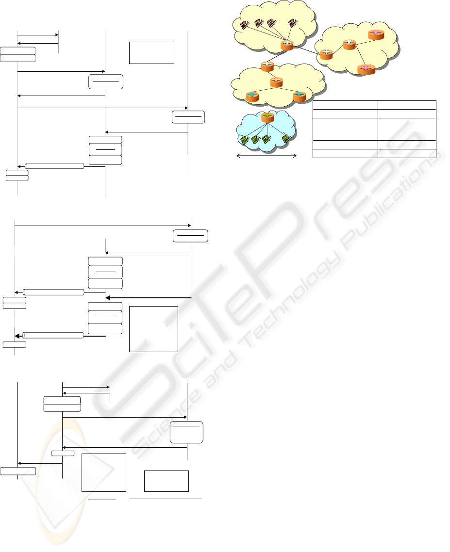
Figure 8 shows the sequence for connecting
MN1 to MR1 in the case where MR1 is already
connected to AR1. MN1 creates its LCoA (A:1::1)
and its ACoA (AGR1 address) from the RAdv
received from MR1. Next, MN1 sends a BU with its
LCoA to AGR1, and a BU containing the ACoA to
its HA. At that time, AGR1 caches the relation that
MN-CoA1 is from the CoP of MR1.
Figure 9 shows the sequence of route
optimization from CN1 to MN1. MN1 sends a BU to
register the binding information that MN-CoA1 is
ACoA (AGR1 address). In this situation, CN1 can
send packets destined to MN1 via AGR1 using
RHO. AGR1 encapsulates this packet with the LCoA
(A:1::1) of MN1 after locating the LCoA (A:1::1) of
MN1 in its binding cache and transmits this packet
to MN1.
Figure 10 shows the sequence triggered by
moving network handoff. MR1 updates its CoP and
informs AGR1 of the update, after getting the new
CoP (B:1::). The subnet mask of this new CoP
should be the same as that of the previous CoP
(A:1::). When AGR1 updates the CoP of MR1,
AGR1 also updates all the LCoAs of all MNs since
they are also subordinates of MR1. More precisely,
only the common information is updated, since MN1
creates its new LCoA after receiving RAdv, which
contains the new CoP (B:1::) sent by MR1. In CoPR,
MN-CoA1 (B:1::1), which AGR1 manages, has
already been updated so that it is not necessary for
MN1 to send a BU to AGR1. In this way, BUs can
be omitted from each MN in the moving network to
the AGR. If the AGR address is changed, it is
necessary to update ACoAs of MN1 and MR1.
5 PERFORMANCE EVALUATION
We have evaluated CoPR, Basic and RRH, using
network simulator 2. Figure 11 shows the parameters
and the topology used in the simulation.
This simulation assumed that the AGR location
was optimal, as shown in Figure 11. The simulation
time was 10 seconds, and the first 2 seconds were
discarded to eliminate the influence of jitter. We
evaluated each mechanism assuming 1, 5, 10, 100,
CNs
MR’s HA
MN’s HA
AR
AR
MR
MNs
2sHandoff interval
G.723.1(6.3Kbps)
* Num. of MNs
(packet size: 24byte)
Data trans. Rate
(CNs -> MNs)
20msL2 disconnected time
11Mbps (1ms)Wireless Link (link delay)
100Mbps (1ms)Wired Link (link delay)
Movement range
AGR
CNs
MR’s HA
MN’s HA
AR
AR
MR
MNs
2sHandoff interval
G.723.1(6.3Kbps)
* Num. of MNs
(packet size: 24byte)
Data trans. Rate
(CNs -> MNs)
20msL2 disconnected time
11Mbps (1ms)Wireless Link (link delay)
100Mbps (1ms)Wired Link (link delay)
Movement range
AGR
Figure 11: Simulation Conditions
AGR1
MN1
BC search
HoA.yA:1::1
encap
RHO proc
IPinIP ( DA=A:1::1)
CN1
BindingCache
HoA.xAGR1
BA (SA=CN1, DA=AGR1, RHO=HoA.y)
BC search
HoA.yA:1::1
encap
RHO proc
IPinIP ( DA=A:1::1)
decap
BA proc
DATA (SA=CN1, DA=AGR1, RHO=HoA.y)
decap
BU (SA=A:1::1, DA=CN1, ACoA=AGR1, HoAOpt=HoA.y)
MR1_HoA=HoA.x
MN1_HoA=HoA.y
MR1_CoP=A:1::
ACoA=AGR1
MR1_LCoA=A::1
MN1_LCoA=A:1::1
Figure 9: Optimization of the route to CN
MR1
AGR1
RAdvAGR1, A:1::
decap
BA proc
MN1
HA2(MN1)
MR1_HoA=HoA.x
MN1_HoA=HoA.y
MR1_CoP=A:1::
BU(SA=A:1::1, DA=AGR1, HoAOpt=HoA.y)
BindingCache
HoA.yAR1.1y
BindingCache
HoA.yAGR1
BA (SA=HA2, DA=AGR1, RHO=HoA.y)
BC search
HoA.yA:1::1
encap
RHO proc
IPinIP ( DA=A:1::1)
BA (SA=AGR1, DA=A:1::1, RHO=HoA.y)
RSol
LCoA gen
A:1::1
ACoA gen
AGR1
BU (SA=A:1::1, DA=HA2, ACoA=AGR1, HoAOpt=HoA.y)
Figure 8: MN joins
MR1
AR2
AGR1
RSol CoP req
MN1
RAdv (AGR1, B:1::)
LCoA gen
B::1
CoP reg
B:1::
BU (SA=B::1, DA=AGR1, HoAOpt=HoA.x, CoP=B:1::)
BindingCache
MR1.CoPB:1::
HoA.xB::1
HoA.yB:1::1
BA (SA=AGR1, DA=B::1, RHOr=HoA.x
BA proc
RAdv (AGR1, B:1::)
MR1_CoP=B:1::
MR1_LCoA=B::1
MN1_LCoA=B:1::1
After handoff (only changed addresses)
Before handoff
MR1_HoA=HoA.x
MN1_HoA=HoA.y
MR1_CoP=A:1::
ACoA=AGR1
MR1_LCoA=A::1
MN1_LCoA=A:1::1
LCoA gen
B:1::1
Figure 10: Handoff
ICETE 2004 - WIRELESS COMMUNICATION SYSTEMS AND NETWORKS
118
and 500 MNs in the moving network. The following
items were evaluated:
(1) E2E delay
(2) Amount of received data / total network
resources used
(3) Handoff signal overhead
(4) Handoff latency
(5) Amount of packet loss
Item 1 is the mean delay of packet transmission
from a CN to an MN in the moving network, and
indicates the degree of route optimization. Item 2
indicates the throughput on each hop. This should
increase if the route is optimized, packet header size
is minimized, and discarded packets are minimized.
The inverse of this measure indicates the network
resource that should be provided for given traffic.
Item 3 is the number of handoff signals, i.e. RSol,
RAdv, BU, and Binding Ack (BA) (Johnson, 2004),
per handoff. Item 4 is the mean time from handoff
initiation to completion. Item 5 is the total discarded
packets caused by the handoff. Items 3 to 5 also
indicate handoff performance.
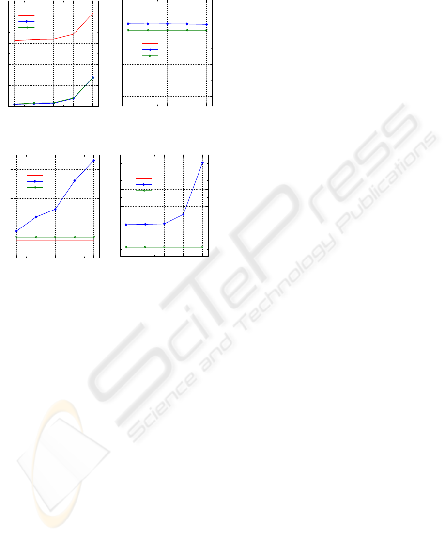
Comparisons for items 1 and 2 for various
numbers of MNs are shown in Figures 12 and 13.
With respect to items 1 and 2, the results of
CoPR are good as shown in each figure. This is
because CoPR implements both route optimization
and minimization of packet header size.
With regard to item 1, CoPR is superior to Basic
in terms of performance regardless of the number of
MNs. The degree of superiority would increase if the
HA is separated from the MR, because the packets
must pass through the bidirectional tunnel from the
MR to its HA. On the other hand, CoPR and RRH
offer similar levels of performance since both of
them optimize routing.
With regard to item 2, the ratio of CoPR
performance to those of the conventional methods is
almost independent of the number of MNs. The ratio
is 1.90 when compared to Basic. This shows that
CoPR transmits data more efficiently than Basic.
This difference is due to the difference in
encapsulation distance of Basic and CoPR. Basic
uses a longer encapsulation distance, from the MR to
its HA, whereas CoPR encapsulates only the route
from the MN to the AGR. On the other hand, the
performance ratio is 0.94 for RRH. The reason is as
follows. In RRH, packets are transmitted with an
RHO that sets two CoAs, MR-CoA and MN-CoA,
from the CN to the MN. In comparison, in CoPR, the
packets are transmitted with an RHO that sets one
AGR address from the CN to the AGR, and also by
encapsulation from the AGR to the MN. Therefore,
CoPR is better and this ratio is larger if the CN is
farther from the moving network than considered in
this simulation environment. The reciprocal of item
2 represents the network resources needed to support
the traffic of a new service. In other words,
increasing item 2 makes it cheaper to put a service
into operation.
Items 3 and 4 for RRH change rapidly with the
number of MNs. Figures 14 and 15 show the
comparisons for various numbers of MNs.
With regard to item 3, both Basic and CoPR
offer low and constant values. On the other hand, in
RRH, increasing the number of MNs increases the
number of handoff signals. Specifically, if the
number of MNs is 500, CoPR has about the same
level of performance as Basic, while it requires
2,000 fewer handoff signals than RRH. The reason is
that RRH demands that all MNs in the moving
network send a BU to each CN and HA.
For item 4, the performance ratio of CoPR to
Basic is 0.38, regardless of the number of MNs. This
difference depends on the BU destination. If the HA
of the MR is located farther from the moving
network than considered in this simulation
environment, the degree of superiority of CoPR
would increase. On the other hand, the ratio of CoPR
to RRH depends on the number of MNs, e.g. 0.32
with one MN, 0.11 with 500 MNs. This shows that
CoPR has lower handoff latency than RRH. The
superiority of CoPR over RRH is due to the fact that
Basic
RRH
CoPR
Num. of MNs in Moving Network
E2E delay (s)
(Item 1)
1510100500
0.006
0.008
0.01
0.012
0.014
0.016
Basic
RRH
CoPR
Num. of MNs in Moving Network
Amount of received data / Total network resources used
(Item 2)
1 5 10 100 500
0.01
0.02
0.03
0.04
Figure 12: Comparison over Num. of MNs (Item 1).
Figure 13: Comparison over Num. of MNs (Item 2)
Basic
RRH
CoPR
Num. of MNs in Moving Network
Num. of handoff signals
Num. of MNs in Moving Network
(Item 3)
1510100500
1
10
100
1000
Basic
RRH
CoPR
Num. of MNs in Moving Network
Handoff latency (s)
(Item 4)
1 5 10 100 500
0.01
0.02
0.03
0.04
0.05
0.06
Figure 14: Comparison over Num. of MNs (Item 3)
Figure 15: Comparison over Num. of MNs (Item 4)
CARE-OF-PREFIX ROUTING FOR MOVING NETWORKS IN MOBILE IP NETWORK
119
the BU destination is only the AGR in CoPR,
compared to all CNs and all HAs in RRH. Therefore,
if the number of CNs and MNs in the moving
network is increased or the distance between an MN
and its HA, or between an MN and a CN is
increased, the handoff latency of RRH increases
dramatically. In short, CoPR is much better than
RRH.
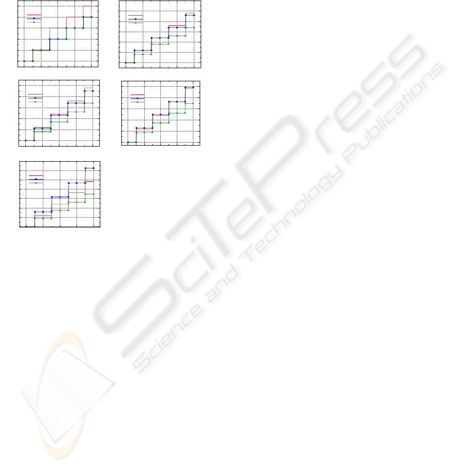
Figure 16 shows the comparisons for different
numbers of MNs regarding item 5, i.e., the total
packet loss. As these figures show, the amount of
discarded packets on CoPR is the smallest of the
three methods, regardless of the number of MNs.
Additionally, the three methods have different time
ranges of discarded packets. For Basic, it is from the
L2 disconnect time until the binding information that
the MR’s HA manages is updated. For RRH, it is
from the L2 disconnect time until the binding
information that each CN manages is updated. For
CoPR, it is from the L2 disconnect time until the
binding information the AGR manages is updated.
This value of RRH becomes worse than those of the
other methods as the number of MNs increases. This
is because the number of handoff signals increases as
the number of MNs grows.
6 CONCLUSION
This paper clarified the difference between host
mobility support and conventional moving network
mobility support, and proposed new routing
mechanisms for moving network mobility support
that meet all requirements. Specifically, this paper
proposed four basic techniques: Care of Prefix,
which minimizes the packet header size,
Concatenated HAs and Hierarchical Address
Management, which reduce the number and volume
of handoff signals, Aggregate Router, which
aggregates and localizes handoff signals, and CoPR,
which is a mechanism for applying these basic
techniques to MIP.
We verified the effectiveness of our proposed
mechanisms using network simulator 2. Quantitative
analyses showed that CoPR is the best in terms of
five measures: E2E delay, amount of effective
received data / total used network resources, amount
of handoff signals, handoff latency, and amount of
discarded packets. As mentioned above, CoPR is
superior to the conventional solutions proposed in
NEMO. We will construct an experimental system
and verify the feasibility of the proposal
mechanisms.
ACKNOWLEDGMENTS
The authors would like to thank Mr. Yoshizawa and
Mr. Fukazawa of NTT COMWARE Corporation for
their useful advice on the simulation.
REFERENCES
IETF, Available: http://www.ietf.org/
Yumiba, H., Imai, K. & Yabusaki, M.. 2001. IP-Based
IMT Network Platform, In IEEE Personal
Communication Magazine, pp.18-23
Johnson, D., Perkins, C. & Arkko, J. 2004. Mobility
Support in IPv6, RFC3775
NEMO, Available: http://www.mobilenetworks.org/nemo/
The Network Simulator, Available:
http://www.isi.edu/nsnam/ns/
Devarapalli, V., Wakikawa, R., Petrescu, A. & Thubert, P.
2004. Network Mobility (NEMO) Basic Support
Protocol, Internet Draft: draft-ietf-nemo-basic-
support-03.txt
Thubert, P. & Molteni, M. 2004. IPv6 Reverse Routing
Header and its application to Mobile Networks,
Internet Draft: draft-thubert-nemo-reverse-routing-
header-05.txt
Deering, S. & Hinden, R. 1998. Internet Protocol, Version
6 (IPv6) specification, RFC2460
Suzuki, T., Hiyama, S., Igarashi, K., Kawakami, S. &
Hirata, S. 2003. Routing Management for Moving
Network, In IEICE General Conference.
Basic
RRH
CoPR
Time (s)
Total packet loss
(a) Case of one MN in Moving Network
246810
0
1
2
3
4
5
Basic
RRH
CoPR
Time (s)
Total packet loss
(b) Case of five MNs in Moving Network
246810
0
5
10
15
20
25
30
Basic
RRH
CoPR
Time (s)
Total packet loss
(c) Case of ten MNs in Moving Network
246810
0
10
20
30
40
50
Basic
RRH
CoPR
Time (s)
Total packet loss
(d) Case of 100 MNs in Moving Network
246810
0
100
200
300
400
500
Basic
RRH
CoPR
Time (s)
Tot al p acket loss
(e) Case of 500 MNs in Moving Network
246810
0
500
1000
1500
2000
2500
3000
3500
Figure 16: Comparison on each case (Item 5)
ICETE 2004 - WIRELESS COMMUNICATION SYSTEMS AND NETWORKS
120
