
A METHOD FOR THE PERFORMANCE ANALYSIS OF
INTEGRATED APPLICATION SERVICES
Simulating the execution of integrated application services
coordinated by workflow-driven broker-servers
Hiroshi Yamada, Akira Kawaguchi
NTT Service Integration Laboratories, 3-9-11, Midori-cho, Musashino-shi, Tokyo, 180-8585, Japan
Keywords: EAI (enterprise application integration), business process, UML (unified modeling language), performance
evaluation, Web service, simulation, OPNET
Abstract: Most EAI tools facilitate the integration of several application services to implement a designed workflow
process. The individual application systems are coordinated by a workflow-driven broker-server that
integrates the system through web-service technologies such as SOAP and XML. This paper describes a
performance-evaluation methodology that we have developed for the analysis of such integrated application
services. Elements of the methodology include a method for the design and implementation of application-
traffic models as UML sequence diagrams and the implementation of workflow-process models as UML
activity diagrams. On this basis, we develop a set of OPNET process models to represent the functions of
workflow-driven broker-servers. We also develop application-traffic and workflow-process node models
that configure the OPNET broker-server models into simulated networks, provide the other components of
the networks, and specify the flows of data and control. Such OPNET models allow us to simulate
integrated services that are driven by workflow-process descriptions, vary the network architecture scenario,
and evaluate the resulting overall performance. Applying the proposed methodology from the early stages
of development of systems will help us to avoid later problems with performance. We also give an example
of a simple case study of the methodology’s application.
1 INTRODUCTION
In many enterprises, particular application systems
run on different computers. Most business processes
consists of several procedures, each of which may be
handled by a different application systems.
However, the individual application systems are not
systematically integrated. Therefore, the user must
sometimes manually input results from one
application system to another application system.
This manual procedure delays the business process
and increases the possibility of mistakes and the cost
of the service. To improve and speed up business
processes and decrease costs, many enterprises are
adopting enterprise application technologies and the
associated tools.
In implementing EAI tools to integrate multiple
existing application systems, we have to resolve
several issues. Many application systems have their
own data structures. Therefore, successfully
exchange of data by the broker-server that integrates
the several application systems has to be able to
handle the several data structures used by the
various application systems, for example, CSV,
XML, etc. The broker-server must understand the
workflow process in the integrated service and
invoke the appropriate application services for the
respective phases of the workflow activity to
implement the designed workflow process.
Transitions of the workflow activity may depend on
parameters of the client requests or on system
conditions.
Applications must be subjected to performance
analysis from the early stages of their development.
Conne Smith used the term “performance
engineering” to indicate the application of
performance-evaluation techniques to software
systems (Smith, 1990). The behaviour of
communications between applications running on
several computers connected by networks is
becoming more complex. We have to evaluate the
overall performance of the integrated service as well
275
Yamada H. (2004).
A METHOD FOR THE PERFORMANCE ANALYSIS OF INTEGRATED APPLICATION SERVICES - Simulating the execution of integrated application
services.
In Proceedings of the First International Conference on E-Business and Telecommunication Networks, pages 275-280
DOI: 10.5220/0001383702750280
Copyright
c
SciTePress

as the performance of the individual applications of
which it is composed. When we consider integrated
services in which EAI tools are used from the
viewpoint of performance, the time taken to
complete delivery of the overall integrated service
through workflow activity is one of the most
important performance measures. Traffic generation
by each application is governed by the workflow
process, so traffic patterns generated by applications
working together are correlated with each other.
Traffic from one application will often cause
multiple other applications to simultaneously
generate traffic. In such cases, an increase in traffic
from one application leads to an increase in traffic
from related applications. Therefore, in designing
the architecture and capacity of the network and
server resources, the IT-system designers will have
to cooperate with the application developers and
consider the workflow process and the
characteristics of application traffic invoked during
execution of the designed workflow process.
In this paper, we propose a methodology for
evaluating the performance of generic EAI systems
of the kind described above, i.e. where the broker-
server has a workflow engine that invokes
applications according to the workflow process. The
network is in a hub and spoke configuration with the
broker at the center. The proposed methodology
involves step-by-step modeling of the following
items: (i) the workflow process, (ii) the traffic-
communication paths of applications, (iii) the
network and server system, and (iv) defining the
applications invoked in the various phases of the
workflow activity (binding of applications to the
workflow process). For the proposed methodology
to be practicable, we developed OPNET (OPNET)
process and node models to realize the functions of
the above workflow-driven broker-server.
This paper is organized as follows. In the next
section, we briefly survey past works about the
performance engineering in application. In section 3,
we give an overview of the proposed methodology.
In section 4, we briefly cover OPNET modeling of
the workflow broker-server and the workflow
processing. In section 5, we describe a simple case
study of the application of this methodology. We
close with a very brief review and a couple of ideas
we are working on to improve the proposed
methodology.
2 PERFORMANCE
ENGINEERING IN
APPLICATION
The unified modeling language (UML) is currently
the best tool we have that encompasses the
information, business systems, and technical
architecture (Erikson, 2000). Korthaus proposed the
BOOSTER (Business-Object-Oriented Software
Technology for Enterprise Reengineering) process
(Korthaus, 1998; Schder, 1998) as a multilevel
approach to business-object-based system
development. A “multilevel process architecture”
defines the framework for the activities which have
to be performed. The BOOSTER process
architecture has four levels: business engineering,
system-architecture engineering, application
engineering, and “business-object component”
engineering. Korthaus has summarized the activities
in each level of engineering and the UML diagrams
that should be used in engineering activities
(Korthaus, 1998). Aoyama (2002) described another
framework for the creation of business-driven web
services. Aoyama’s model for the development of
web services consists of business-process,
application, and platform layers. The UML is the
common language for development of the
application software. When the model that defines
an IT system is written in UML, it is convenient to
use UML as the basis for defining models to be used
in evaluating the IT system. Pooley et al. (1999)
summarized past approaches to software-
performance engineering and proposed some ideas
on the exploitation of UML designs in performance
modeling. Here, the use-case diagram provides the
basis for the definition of workloads in the system.
Implementation diagrams provide the mapping onto
computing and storage devices. They are essential
to definition of contention and the quantification of
available resources. Correspondences are then
drawn between the implementation diagrams and an
underlying queuing model. Finally, the behaviour of
the above queuing model is obtained either through
queuing-network analysis or simulation. Balsamo et
al. (2003) proposed a simulation-based approach to
the performance modeling of software architectures
specified in UML. They defined a way to set up
process-oriented simulation models of UML
software specifications. Correspondences between
UML and simulator objects are as follows: use-case
diagrams correspond to the workload models, the
deployment diagrams correspond to resources
models, and the activity diagrams correspond to the
steps of the simulation. They called the prototype
version of this tool UML-Ψ, which is intended to
indicate “UML performance simulator.”
ICETE 2004 - GLOBAL COMMUNICATION INFORMATION SYSTEMS AND SERVICES
276
Most of the above-cited researches are focused
on the performance of software running on a single
computer or simple application of the client-server
type. Our methodology expands UML-based
software performance engineering to cover
distributed and integrated applications.
Furthermore, as mentioned, an EAI tool can
orchestrate several applications to implement a
workflow processes. In our methodology, the UML
activity diagrams are set up in the OPNET simulator.
3 METHODOLOGY
In designing a commercial or other business-related
IT system, the system designer has to consider a
three-layered model, consisting of the business-
process layer (BP layer), application layer (AP
layer), and network/system layer (NW layer). We
create the following UML diagrams in the BP layer:
the use-case diagram, which shows the relationship
between the system and its users, the activity
diagram, which shows how the user uses the system,
the class diagram, which shows the objects needed
in order to realize the application, and the sequence
diagram, which shows the relationships between
objects within the application procedures. The
above information is useful in development of the
software for the AP layer and in evaluating the
performance of the business processes and
applications. Levels of performance of the
applications should be examined in a small-network
environment before they are deployed within the
larger enterprise. In the NW layer, the designer is
required to plan and design the NW and system
architecture and capacities so that the overall IT
system does not violate the conditions of service
level agreements (SLAs).
In our proposed methodology for performance
engineering, modeling proceeds from layer to layer
(BP/AP/NW, in that order). Evaluating the overall
performance of an integrated service set up by the
EAI broker-server and its workflow-driven engine
requires that the workflow model be modeled in the
BP layer. For this task, an activity diagram of the
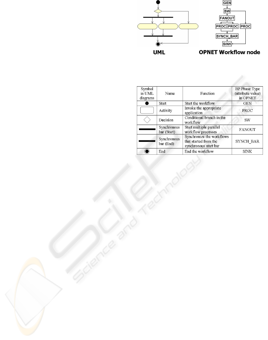
type shown in the figure 1 is useful. The workflow
process is modeled by using the OPNET Node
Editor. We combined process and link modules to
create the activity diagram shown in the figure 1.
Each process module represents the function of an
element of the activity diagram. The process
modules are connected by link modules to set up the
same topology as that in the activity diagram. The
mapping between the functions of the elements of
the activity diagram in UML and the attributes set in
the OPNET process modules is shown in table 1.
In the AP layer, we model the path of each
application service in the various phases of the
workflow invoked by the workflow-driven broker-
server. The communication path is defined as the
sequence of communications among servers and
clients. The probability density functions (pdf) of
message size, the intervals between messages, and
numbers of messages sent between servers and
clients are required to describe the traffic on the
paths. The above information is set as attributes of
the application task utility node model in OPNET
model. The sequence diagram is then used in
making the application model.
In the NW layer, we use OPNET to create a
virtual network environment. This model represents
the configurations, i.e., the interfaces, routing
protocols, etc., of the routers and switches within the
network. Finally, we should bind the appropriate
application to each phase of the designed workflow.
These bindings are set up as attributes of the BP/AP
binding node model.
After these modeling procedures, we are ready to
run the simulation model that simulates the
behaviour of the application processes integrated by
the workflow-driven broker-server. We can
compare the overall completion times of integrated
application services. We can perform what-if design
tests, where we vary the workflow diagram, the
application sequence diagram, traffic volume, or
network and system configuration, simulate the
modified model, and then compare the results on
performance.
Figure 1: A UML activity diagram and an OPNET
workflow model
Table 1: Mapping the elements of a UML Activity
Diagram to the attributes of OPNET process models
A METHOD FOR THE PERFORMANCE ANALYSIS OF INTEGRATED APPLICATION SERVICES - Simulating the
execution of integrated application services
277
4 OPNET MODELING
In this section, we briefly describe the use of
OPNET to model workflow-description node models
and workflow-driven broker-servers. OPNET is
simulation and management software for networks
and applications. This software gives us a way to
create simulation models of our customized
protocols and node models.
We use the OPNET Node Editor to make
workflow-description node models that represent
workflow processes. Each such model consists of
process modules and links. Each process module
corresponds to an element of the UML activity
diagram, as shown in table 1. Links connect process
modules. We set up these models by selecting
process modules from the OPNET Node Editor
Palette, placing the modules, and then using link
objects to connect the process modules in the same
way as the elements of the UML activity diagram.
We then set the attributes of the module; i.e., the
name of the workflow and phase in the workflow
process, and a maximum time over which a WPE is
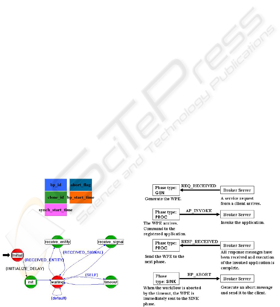
allowed to stay in that phase. The WPE is a virtual
packet that flows within the diagram of the process
modules (as set up with OPNET workflow-
description nodes). Its format is as shown in figure
2. The bp_id is a unique identifier for the WPE
immediately after the broker-server has received the
request from the client and generated the WPE in
response. The abort_flag indicates when the
workflow process has been aborted in the mid-flow.
The field bp_start_time is used to determine
whether or not the overall workflow process has
taken too much time. The fields clone_id and
synch_start_time are used to manage parallel
processing between synchronous bars of UML
diagrams. If a WPE exists in the phase A in the
workflow process B, then the current state of the
workflow process B is A, that is, all activities of the
phases prior to the phase A in the workflow B have
been done.
After modeling the workflow process, our next
step is to configure the binding procedure, in which
we define the correspondences between phase names
in the workflow description and phase-type
attributes of UML elements. This is shown in the
table 1. Next, we define flags that indicate whether
or not an application is invoked in that phase; if an
application is invoked, its name is also set as an
attribute. The application name should be the same
as the name defined in the OPNET application task
utility node. The above binding procedure ensures
that the simulation process invokes a defined
application when the WPE arrives at the
corresponding phase of the workflow process.
A common process model runs on each process
module; the state diagram of this model is given as
figure 3. After the initialization procedure, the
workflow-simulation process enters the waiting
state. When the workflow simulation process is
interrupted by the REQ_RECEIVED signal from the
broker-server simulation process, it enters the
receive_signal state and processes the WPE, and
then sends the WPE to the next process module,
which represents the next phase of the workflow.
When the WPE arrives at the process module, the
simulation process enters the receive_entity state.
In case that an application is invoked in this phase,
the simulation process then generates an
AP_INVOKE signal, which interrupts the broker-
server process. The broker-server simulation
process invokes the appropriate application for its
Figure 2: Format of work flow-
p
rocess entities
(WPEs); the example is in the initial state
Figure 3: State diagram of processing by all
workflow-simulation
p
rocesses
Figure 4: Communication betwee
n
wo
rkfl
ow
a
c
ti
v
iti
es
an
d
th
e
b
r
o
k
er
-
se
r
ver
ICETE 2004 - GLOBAL COMMUNICATION INFORMATION SYSTEMS AND SERVICES
278
current state and sends any required request
messages to the application servers. As stated
above, the WPE is only allowed to stay in a
workflow-simulation process for a per-process
specified maximum time. A process is aborted if
this maximum is reached, that is, the workflow-
simulation process enters the timeout state. The
interrupting signal that flow between the workflow
and the broker-server simulation processes are
summarized in figure 4.
5 CASE STUDY
In this section, we describe how we set up a
performance-analysis simulation of an integrated-
application as a case study to illustrate the
effectiveness of the proposed methodology.
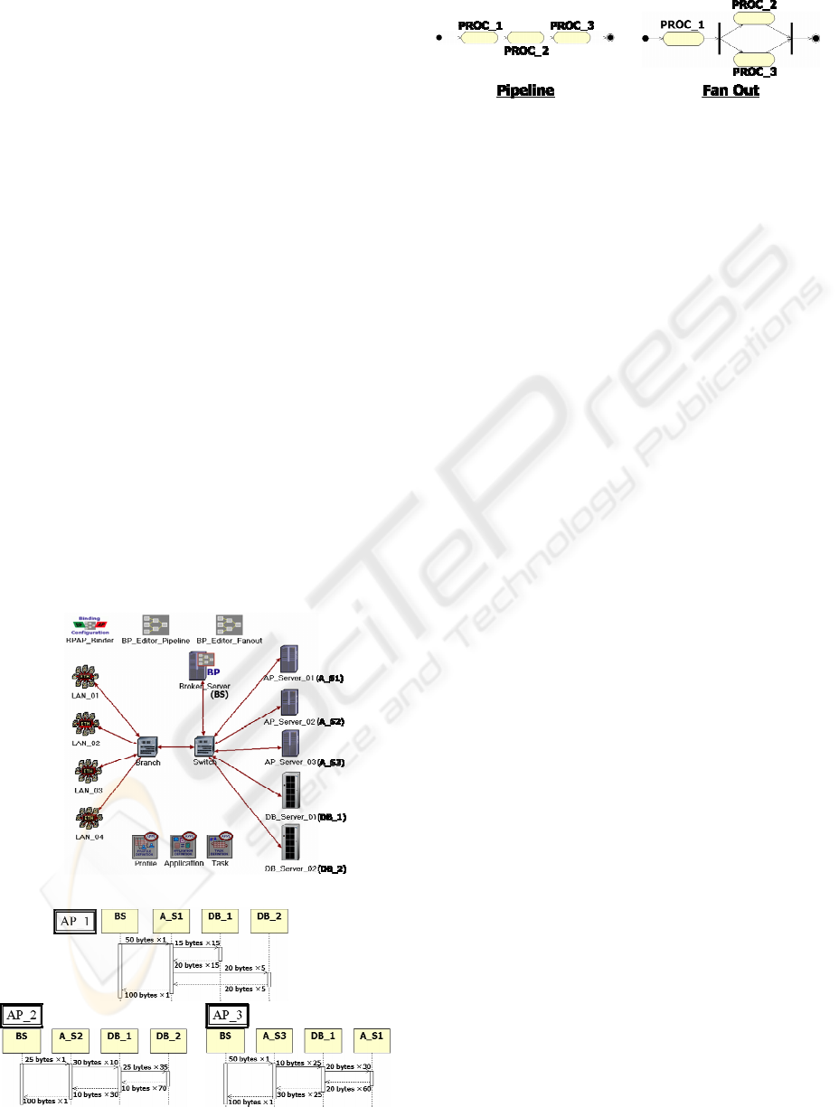
We consider three multi-tiered applications and
integrate them with a workflow-driven broker-
server. The network configuration is shown in figure
5. The sequence diagrams of the three applications,
AP_1, AP_2, and AP_3, are given in figure 6.
Traffic information on the application messages is
added to the sequence diagram. This information is
configured in the OPNET application task utility
node model. Figure 7 shows two UML activity
diagrams for comparison, one of the pipeline-type
and the other of partial fan-out-type. Each activity
diagram has three phases of activity. The names of
the invoked applications in PROC_1, PROC_2,
and PROC_3 are AP_1, AP_2, and AP_3
respectively. In this case study, applications AP_2
and AP_3 access DB_server_01. Processing in the
PROC_2 and PROC_3 phases is parallel because
of the fan-out workflow model, so conflicts of
requests to DB_server_01 will occur. To
emphasise how differences between workflow
activity processes affect performance and the need
for the workflow designer to consider IT-system
resources, we configure DB_server_01 so that its
CPU only has half the power of the CPU in
DB_server_02.
In this case study, generation of client requests is
according to a stochastic process. In the first
scenario, each client in the LAN node starts to send
its first request according to a uniform distribution
across the simulation interval from 20 to 110. The
pdf of the interval between consecutive requests
after the first request is sent is an exponential
distribution with a mean of 90. Processes for
consecutive intervals are identical and independent.
In the second scenario, the request-generation
process has two modes, ON and OFF. The start of
the first period in ON mode is governed by a
uniform distribution across the simulation interval
from 20 to 320. During periods in ON mode, the pdf
of the intervals between consecutive requests from
each client is an exponential distribution with a
mean of 30. The period in ON mode is a constant
300. Requests are not generated during periods in
OFF mode. The period in OFF mode is a constant
600. So, in both cases, requests from each client are
generated once every 90 on average. The difference
is that requests are concentrated in short intervals in
the case of the second scenario.
Figure 8 shows the completion times for the first
scenario of integrated application services.
Completion times are shorter for the parallel fan-out-
type workflow than for the pipeline-type workflow.
However, when we compare the completion times
for each application, the average completion times
for AP_2 and AP_3, which are executed as parallel
fan-out-type workflows, are longer than those for the
pipeline-type workflows. Requests to
DB_server_01 are concentrated in the period of
parallel fan-out-type workflow. Figure 9 shows
completion times for the second scenario. The
completion time for the parallel fan-out-type
workflow is greater than that for the pipeline-type
Figure 6: Sequence diagrams
Figure 7: Workflow models
Figure 5: Network model
A METHOD FOR THE PERFORMANCE ANALYSIS OF INTEGRATED APPLICATION SERVICES - Simulating the
execution of integrated application services
279
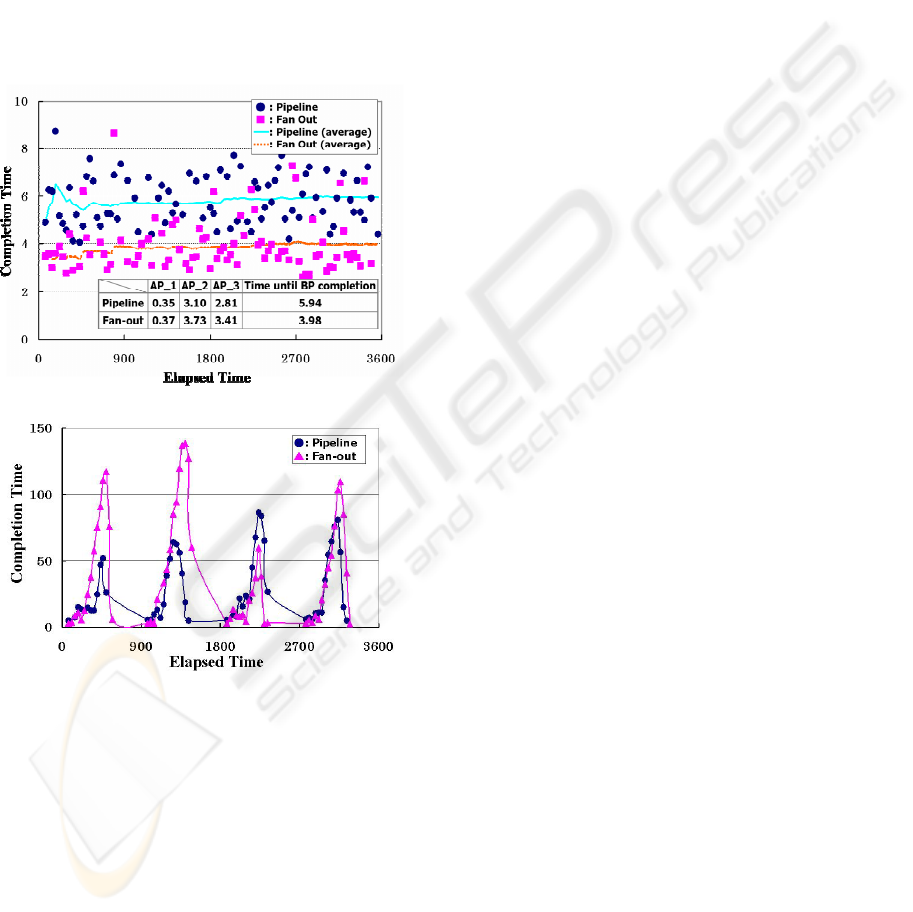
workflow during busy period, i.e. the period where
the request-generating processes of several clients
are simultaneously in ON mode. This gives us some
idea of how the performance of an integrated service
is affected by the workflow design, application
characteristics, IT resources and architecture, and
pattern of usage. IT-system and application designer
thus have to cooperate in evaluating the performance
of the application at every milestone of the
development process. In this process of evaluation,
the UML provides both a useful common language
and the basis of a methodology for evaluating the
performance of integrated services coordinated by
the workflow-driven broker-servers.
6 CONCLUSION
In this paper, we propose a methodology for
evaluating the performance of generic EAI systems,
of the type where a broker-server has a workflow
engine which invokes appropriate application to
implement a workflow. To demonstrate the
practicability of the proposed methodology, we
developed OPNET models of processes and nodes to
realize the functions of workflow-driven broker-
servers as described above. We are expanding the
broker-server module so that it can handle WPEs
which include information specifying actual XML
files for transfer in the simulated workflow process
and directions for the workflow process (a form of
branch control).
REFERENCES
Conne Smith 1990. Performance Engineering of Software
Systems. Addison-Wesley, Reading, Massachusetts.
Erickson and Penker, 2000. Business Modeling with UML,
John Wiley & Sons, Inc.
A. Korthaus and S. Kuhlins, 1998. BOOSTER process—a
software development process model integrating
business object technology and UML, in Beyond the
Notation: Selected Papers from the First International
Workshop on the Unified Modeling Language
<<UML>>’98, Lecture Notes in Computer Science
1618, Springer-Velag, Berlin u.a., pp. 215-226.
Martin Schder and Axel Korthaus, 1998. Modeling
business processes as part of the BOOSTER approach
to business object-oriented system development based
on UML, Proceedings of the Second International
Enterprise Distributed Object Computing Workshop,
3–5 Nov. 1998, La Jolla, California, USA, IEEE,
pp.56–67.
M. Aoyama, 2002. A Business-Driven web service
creation methodology, Proceedings of the
International Workshop on Web Services Engineering,
Nara, Feb. 2002, pp. 225–228.
Rob Pooley and Peter King, 1999. The Unified Modeling
Language and Performance Engineering, IEE
Proceedings on Software, Vol.146, No.1, pp. 2–10,
February 1999.
Simonetta Balsamo and Moreno Marzolla, 2003. A
simulation-based approach to software performance
modeling, Proceedings of the 9th European Software
Engineering Conference, pp. 363–366, 2003.
OPNET, http:/www.opnet.com/.
Figure 9: Completion time (Second scenario)
Figure 8: Completion time (first scenario)
ICETE 2004 - GLOBAL COMMUNICATION INFORMATION SYSTEMS AND SERVICES
280
