
FAST MOBILE IPV6 APPROACH FOR WIRELESS LAN
BASED NETWORKS
Link-Layer Triggering Support for IEEE 802.11
Norbert JORDAN and Alexander POROPATICH
Institute of Broadband Communications, Vienna University of Technology
Favoritenstrasse 9/388, A-1040 Vienna, Austria
Keywords: Mobile IPv6, Fast MIPv6, Wireless LAN, Link-Layer Triggering, Fast IEEE 802.11 Handover.
Abstract: The standard Mobile IPv6 specification provides comprehensive mobility management for the IPv6 proto-
col. During the handover there is a period in which the mobile node is unable to send or receive packets due
to link-layer switching and IPv6 protocol layer operations. This overall handoff latency resulting from base-
line MIPv6 procedures, namely movement detection, new care-of address configuration, and binding up-
dates with peer entities, is often unacceptable for any kind of real-time service (video-conferencing, voice-
over-IP,…). A new fast handover approach, based on Fast Handovers for Mobile IPv6, is proposed in this
paper, which will support seamless movement in between IPv6 domains using a IEEE 802.11 network infra-
structure. A new low latency handoff method for IEEE 802.11 will be proposed, where access point beacons
are utilized for carrying IPv6 prefix information without altering the Mobile IP or IEEE 802.11 specifica-
tions. A WLAN service will continuously monitor the radio signal quality of the attached access point and,
if necessary, will switch to another access point in range. This feature and the elimination of firmware-based
active scanning during link-layer handovers have the flavor effect of reducing the overall link-layer handoff
delay to about 10%. We will further introduce our wireless testbed infrastructure for evaluation of the pro-
posed approach. Performance evaluation is used to verify the effectiveness of our implementation and an
extensive simulative comparison is used for scalability analyses.
1 INTRODUCTION
Owing to the assistance of Mobile IPv6 (Johnson,
2004), a mobile node can effectively maintain its IP-
layer connectivity to the Internet when it changes its
point-of-attachment somewhere in the world. During
the accomplishment of the handover, the mobile
node is unable to send or receive IPv6 packets be-
cause of its L2 and also L3 handover operations.
This high handover latency is unacceptable to real-
time applications or delay sensitive traffic. Each
time a mobile client moves, it is necessary to per-
form movement detection by discovering (sending
router solicitation) its current point of attachment.
In Mobile IPv6 (Johnson, 2004), the movement de-
tection algorithm relies on the periodic sending of
router advertisements in order to enable the mobile
node to determine its current location. The only way
to improve the detection performance is to broadcast
router advertisements at a faster rate, which may
result in a poor link utilization. For that reason the
fast handover protocol (Koodli, 2004) is designed to
achieve a seamless handoff when mobile nodes
move from one domain to another.
In a mobile-initiated and anticipated fast-
handover scenario described in (Koodli, 2004), the
mobile node first sends a Router Solicitation for
Proxy (RtSolPr) message to the current access router
containing any Access Point specific identifiers. The
current Access Router replies with a Proxy Router
Advertisement (PrRtrAdv) message , which may
contain a subnet-specific information tuple [AP-ID,
AR-MAC, AR-IP]. This message exchange allows a
mobile node to obtain the new Access Router's pre-
fix information, which is needed to perform an “an-
ticipative” configuration of the new IPv6 address on
the new subnet. Figure 1 presents a general mobile-
initiated “predictive” fast handover scenario.
102
Jordan N. and Poropatich A. (2004).
FAST MOBILE IPV6 APPROACH FOR WIRELESS LAN BASED NETWORKS - Link-Layer Triggering Support for IEEE 802.11.
In Proceedings of the First International Conference on E-Business and Telecommunication Networks, pages 102-108
DOI: 10.5220/0001395301020108
Copyright
c
SciTePress
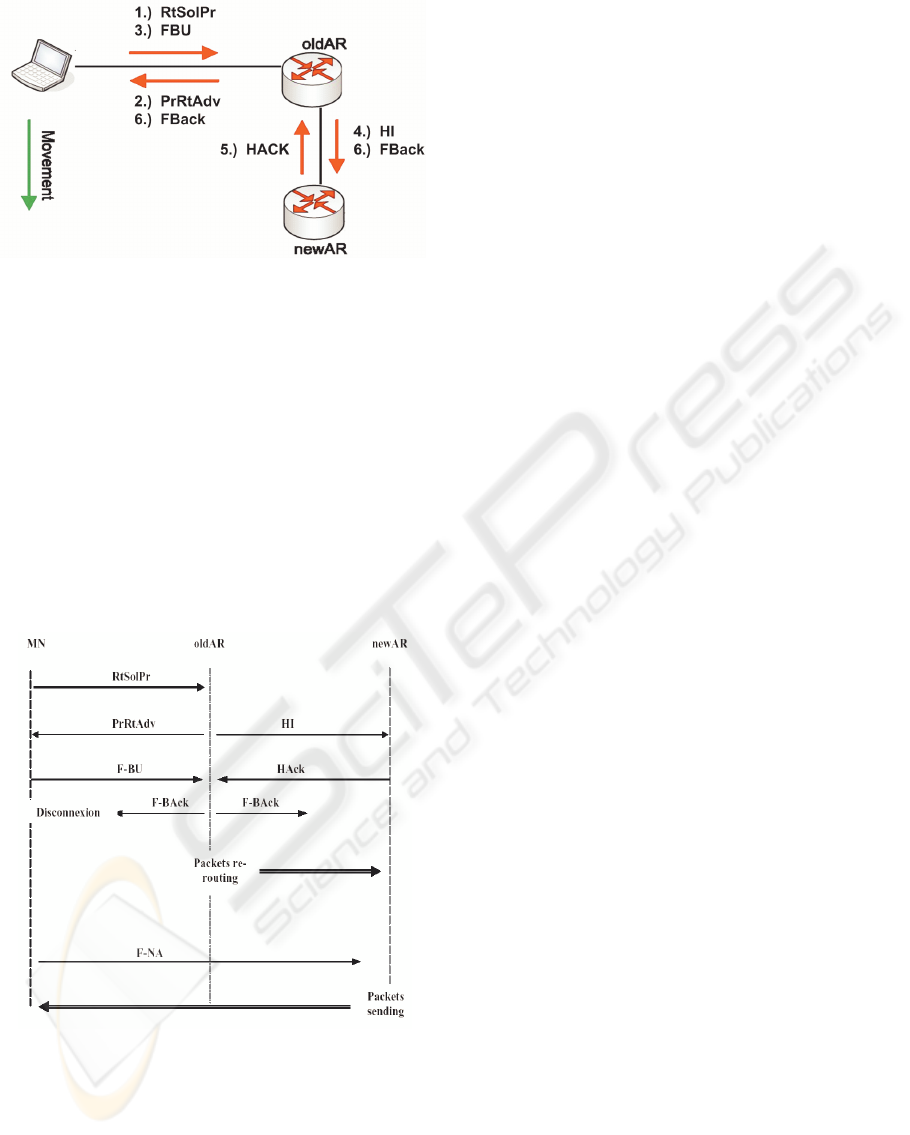
Figure 1: Reference Scenario for FMIPv6 Handover.
With the information provided in the PrRtAdv
message, the MN formulates a prospective new CoA
and sends a Fast Binding Update (FBU) message.
The purpose of FBU is to authorize the old AR to
bind the current Care-of address (CoA) to new CoA,
so that arriving packets can be tunneled to the new
location. Depending on whether an FBack (Fast
Binding Acknowledgement) is received prior to the
Mobile Node’s movement or not, the prospective
address can be used immediately after attaching to
the new subnet link. In case it moves without receiv-
ing an FBack, the MN can still start using the new
CoA after announcing its attachment through a Fast
Neighbor Advertisement (FNA) message (see Figure
2).
Figure 2: Message Flow for Mobile-Initiated HO.
However, the above protocol assumes that the
L2 protocol is capable of delivering the L2 identifier
of the new access point to the mobile node. More
important, to initiate a seamless handover, is the fact
that the current AR must be capable of mapping this
new L2 identifier into the IP address of the target
AR. We will show that all these requirements for
Fast MIPv6 can be fulfilled in our implementation
without any modifications to the IEEE 802.11 stan-
dards.
2 FAST HANDOVER FOR IEEE
802.11
The growing popularity of IEEE 802.11 (IEEE,
1999) has made “wireless” LAN a potential candi-
date technology for providing high speed reliable
wireless access services. In addition by supporting
Mobile IP, wireless LAN can meet demands for ex-
panded wireless access coverage while maintaining
continuous connectivity from one domain into an-
other. In order to be able to accomplish a fast hand-
over on Layer 3 it is necessary to implement a trig-
gered information indicated by the underlying link-
layer driver.
2.1 Link-Layer Triggering
In order to achieve an efficient interworking be-
tween Fast Mobile IPv6 and IEEE 802.11, it is nec-
essary that the link-layer initiates the handover. The
mobile node normally does this by sending a proxy
router solicitation at the IP layer. This action is trig-
gered by the underlying link layer in the mobile
node, which must be aware that a handover is about
to take place. This is the only possible way since
from the IEEE 802.11 link-layer’s point of view the
mobile node is the only entity which is aware, that
the host is about to attach to a new AP. In our im-
plementation there is a tool running at the mobile
node which continuously monitors the signal
strength of the attached AP. In case the receiving
power-level falls below a pre-defined value, the tool
reacts by collecting information of all APs in range.
So the tool is able to anticipate the best destination
for the handover. At the same time of preparing the
link-layer handover to the most qualified AP, the
client-tool will send a trigger message to the fast-
handover module. The next step that follows is the
proposed FMIPv6 approach explained in Section 3.
2.2 Enhanced WLAN Handover
Even if the Fast Mobile IP approach is implemented
properly, there are still delay issues to solve during
the link-layer handover. Since Mobile IP and link-
layer handover should go hand-in-hand, there is still
an unsolved problem with the Layer 2 handoff-
latency when the mobile node moves from one AP
to another. There exists a definite period of time in
which the mobile node is unreachable due to the
FAST MOBILE IPV6 APPROACH FOR WIRELESS LAN BASED NETWORKS - Link-Layer Triggering Support for
IEEE 802.11
103
layer 2 movement (i.e. re-synchronization with the
new AP). It has to be remarked that the exact
amount of time varies, depending on the deployed
WLAN technology. Some measurements (Velayos,
2003) (Velayos, 2004) (Mishra, 2002) for IEEE
802.11b show that this time period can vary from
200 to 1500 ms, depending on the type of vendor
equipment.
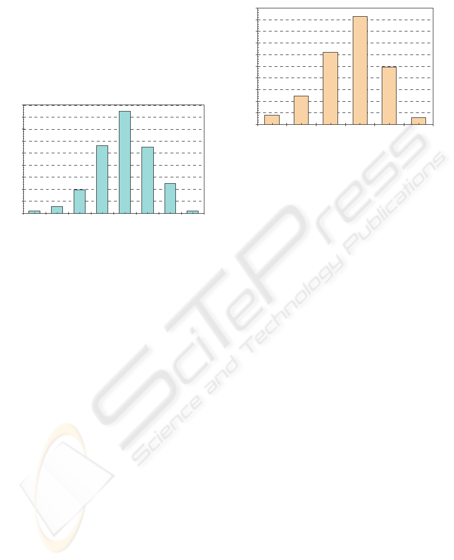
Figure 3: IEEE 802.11b HO Latency without Optimi-
zation.
The main problem during the handover is the
fact that stations have to detect the lack of radio
connectivity based on unsuccessful frame transmis-
sions. The difficulty is to determine the reason for
the failure among collision, radio signal fading or
the station being out of range. In our implementation
the signal strength is monitored continuously. In
case that the signaling level drops below a prede-
fined threshold, the tool automatically tries to hand-
off to an AP in range, which provides a much better
connectivity. So the long phase of detection can be
saved and the handover is carried out much faster.
This WLAN handover-tool takes advantage of the
information provided by the physical layer and com-
pletely skips the detection phase. Stations equipped
with our tool start the search phase when the quality
of the radio-signal falls below a pre-defined thresh-
old. Therefore, the search always starts before any
frame has been lost. This has the favorable effect
that the overall handover-time can be reduced to
about 350ms, as demonstrated in (Jordan, 2003).
Another issue of WLAN is the active-scan process,
which is often enforced with each AP-handover.
Preventing active-scanning, additionally helps to
reduce the link-layer latency to about 60 to 100 ms
(depending on vendor hardware).
Figure 4: Optimized IEEE 802.11b Handover.
These initial improvements will enable wireless
networks to carry real-time applications along the
infrastructure.
3 PROPOSED FAST HANDOVER
APPROACH
As already stated in Section 2 our implementation
helps the Mobile Node to detect if the current link is
degrading and therefore starts searching for a new
AP with improved link-quality. To do this, the mo-
bile node scans all possible frequencies (specified by
the IEEE 802.11b standard) [10] and compares the
received signal with the one currently received. If
the mobile node finds a better signal it can switch to
the new AP. But the mobile node’s link layer im-
plementation does not know whether this AP is at-
tached to a new AR. The link layer only knows
about link layer addresses and the AP’s SSID (Ser-
vice Set Identifier) string. However, if the AP
name/link layer address (which identifies an AP) is
known, the mobile node’s IP-layer implementation
can request that the current AR should provide the
prefix/router address, which the new AP is attached
to. This idea assumes that an AR is configured with
a table containing its own and the neighboring APs
link-layer addresses and their corresponding AR.
In our implementation we configure each access
point involved with a special SSID string (e.g.: SSID
= “2001:200:8:72AB:1434::1/64”) which further
implicitly presents all information about the prefix
of the attached AR. Whenever the mobile node an-
ticipates a handoff, the handover-tool exactly knows
the prefix of the new AR the AP is attached to. In
that way the mobile node performs “anticipative”
configuration of the new IP address on the new sub-
net using the router prefix information carried in the
beacon message of the new AP. If more than one
destination access point is in range, the mobile node
0
20
40
60
80
100
120
140
160
180
600 650 700 750 800 850 900 950
Handoff-Latency (ms)
Occurrence
0
25
50
75
100
125
150
175
200
225
250
50 60 70 80 90 100
Handoff-Latency (ms)
Occurrence
ICETE 2004 - WIRELESS COMMUNICATION SYSTEMS AND NETWORKS
104
could prefer to carry out a movement to an AP
within the same subnet. Thus only a link-layer hand-
over would be performed, which further improves
the handoff-latency in this special case. In all other
cases the mobile node will perform the configuration
of a new IP address and continues with the Fast Mo-
bile IPv6 handover until the mobile node arrives at
the new AR (NAR).
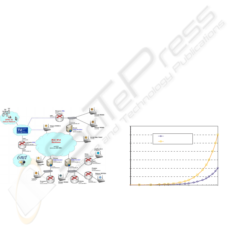
4 IMPLEMENTATION OVER-
VIEW
To make a serious network evaluation in the area of
Mobile IPv6 possible, we implemented an enhanced
IPv6 testbed which is connected to the worldwide
native “6net” infrastructure. As it can be seen in
Figure 5, we built up a central core network where
all subnetworks are attached to. In between each
included network provider, we implemented WAN-
Emulators that thwart all IPv6 packets transmitted.
As our major aim was to create a very flexible net-
work infrastructure, we put a single WAN-Emulator
for each provider. So we are able to tune the link-
delay individually, depending on the appropriate
scenarios to be analyzed. Wireless LAN IEEE
802.11b and IEEE 802.11g are deployed in the over-
all infrastructure.
Figure 5: Mobile IP Testbed at TU-Vienna.
Three independent network operator domains
were deployed, whereas one includes the Home
Agent for the mobile node experiments. Further-
more, another network operator domain includes
some kind of hierarchical structure in order to be
able to do a performance comparison with the alter-
native HMIPv6 approach. All hosts including mobile
nodes, correspondent nodes and the routers within
each provider’s area have RedHat Linux 8.0 in-
stalled with Kernel 2.4.22. For the MIPv6 basis
functionality we utilized MIPL 1.0, provided by
Helsinki University of Technology (HUT).
The Linux driver for all WLAN activities is
based on the HostAP project, which seems to be the
most flexible environment for making link-layer
triggering realizable in a very fast manner. HostAP
provides a general Linux driver for all
PRISM2/2.5/3 based Wireless LAN cards. The re-
sults of an initial link-layer trigger optimization can
be seen in Figure 3 and 4. These measurements are
deployed by skipping the active-scanning mecha-
nism within each handover.
5 PERFORMANCE EVALUATION
In this section we present initial results for a verifi-
cation of the implemented IPv6 mechanisms and
furthermore results based on our real-world Mobile
IPv6 network infrastructure. For all measurements
we derived average-values from about 1000 samples
for each point in the graphics. This helps us to get
significant and serious results for comparing of
standard Mobile IPv6 to the enhanced FMIPv6 ap-
proach.
The first graph presents the difference in be-
tween communication with and without Route Op-
timization. The results of the end-to-end delay, de-
pending on various link-delays, are presented in Fig-
ure 6.
Figure 6: Route Optimization Impact on End-to-End De-
lay.
Figure 7 depicts the dependence of the handoff
latency (foreign link – foreign link) on the variance
of sending Router Advertisements. Obviously, the
handoff latency falls off as Router Advertisement
messages are sent more frequently.
0
0,5
1
1,5
2
2,5
3
3,5
1 10 100 1000
Link Delay (ms)
End-to-End Delay (s)_
MIPv6
no Route Optimization
FAST MOBILE IPV6 APPROACH FOR WIRELESS LAN BASED NETWORKS - Link-Layer Triggering Support for
IEEE 802.11
105
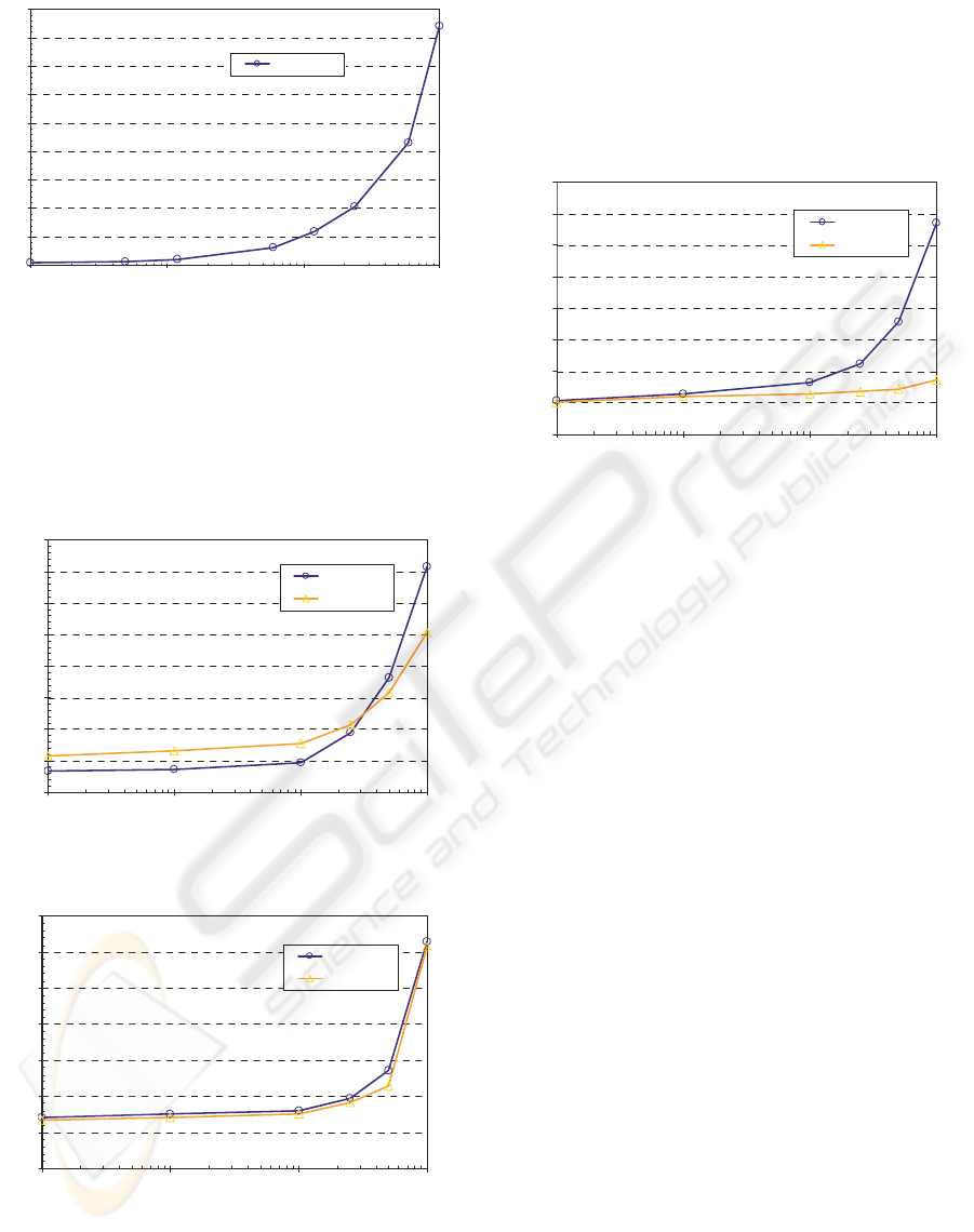
Figure 7: Handoff Latency for varying Router-Adv. Inter-
val.
.
The results in Figure 8 and Figure 9 present the
average handoff latency with dependence on the
link-delay between different networks. Here we di-
rectly compared basic Mobile IP to the Fast MIPv6
approach.
Figure 8: Average Handoff-Delay for Basic Mobile IPv6.
Figure 9: Average Handoff-Delay for Fast Mobile IPv6.
As already assumed from the Fast Mobile IPv6
approach, the packet loss during a handover between
different network providers is decreased to a mini-
mum compared to basic Mobile IPv6. Figure 10 de-
picts the packet loss results for an Iperf- generated
UDP-data stream of 160 kbit/s in between the mo-
bile node and its correspondent node. As illustrated
in Figure 5 the Correspondent Node is placed near
the core network.
Figure 10: Average Number of Packet Loss during HO.
6 SIMULATIVE COMPARISON
For a deeper understanding as well as for a more
general evaluation of Mobile IPv6 in an environment
with many users, the use of simulations is indispen-
sable. We performed a simulative comparison of
baseline Mobile IPv6 and the Fast Handoff approach
in an wireless LAN based scenario, comprising 4
independent operator domains with 10 home users
per access router. Even if the focus is on the evalua-
tion of MIPv6 bases protocols, we also include the
impact of a shared-link environment based on IEEE
802.11b.
6.1 Simulation Scenario
For the performance study of MIPv6 we decided to
evaluate a basic scenario which is simple enough to
get results in a reasonable time but also complex
enough to get an expressive feeling for real-world
provider scenarios. The studied scenario (see Figure
11) is composed of a group of Correspondent Nodes,
one for each Mobile Node, connected to one central
router (CR) through the IPv6 backbone. Each access
router (AR) represents a different IP subnet and acts
as a home agent for 10 mobile nodes. All Mobile
Nodes are located at their home link when the simu-
lation starts. Either the distance in between the ARs
and also the transmitted signal-power are chosen in a
way to create overlapping coverage areas for ena-
bling seamless movement in between the various
domains (see Figure 12).
0
1
2
3
4
5
6
7
8
9
0,01 0,1 1 10
Radvd-Interval (s)
Average Handoff-Latency (s) _
FL-FL (20 -30)
0
2
4
6
8
10
12
14
16
1 10 100 1000
Link Delay (ms)
Average Handoff-Latency (s)_
FL-FL (20 -30 )
HL-FL (10-20)
0
1
2
3
4
5
6
7
1 10 100 1000
Link Delay (ms)
Average Handoff-Latency (s)_
FMIPv6 FL-FL
FMIPv6 HL-FL
0
10
20
30
40
50
60
70
80
1 10 100 1000
Link Delay (ms)
Average packet loss per handoff
Basic MIPv6
Fast MIPv6
ICETE 2004 - WIRELESS COMMUNICATION SYSTEMS AND NETWORKS
106
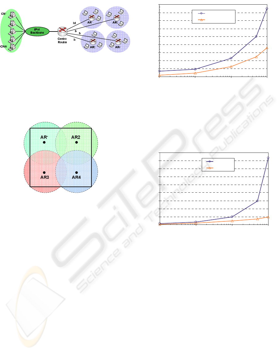
Figure 11: Mobile IPv6 – Simulation Scenario.
The random way-point mobility model is used
for all Mobile Nodes, which is best suited for realis-
tic user movement. Connectivity for each Mobile
Node is provided by IEEE 802.11 using 2 Mbit/s
and DCF and traffic is assumed to be UDP with 40
kbit/s constant bit rate.
Figure 12: Access Router Range Topology.
For all our experiments we used the ns-2 (Ns2,
1998) simulation tool, whereas the MOBIWAN add-
on by Thierry Ernst (Ernst, 2002) is deployed to get
basic MIPv6 functionality into the simulator. Further
essential MIPv6-specific software code was adopted
from a MIPv6 simulation environment by NEC
Europe in Germany.
6.2 FMIPv6 Simulation Results
In this section, we present the results of our ns-2
simulative comparison of baseline Mobile IPv6 and
the enhanced Fast Handover mechanism.
Figure 13 presents the comparison of the handoff
latency obtained during basic Mobile IPv6 handoff
with the latency resulting from a Fast Mobile IPv6
handover. The simulation results show that similar
to the performance measurements in Section 5 we
also achieve some latency-related advantage for sce-
narios with a huge number of concurrent moving
users.
Figure 13: Average Handoff Latency Comparison.
With a reduced latency also the packet loss dur-
ing the handoff can be reduced consequentially for
the Fast Handoff approach. This behavior, similar to
our testbed results from Section 5, is demonstrated
in Figure 14.
Figure 14: Average Packet-Loss per Handover.
7 CONCLUSIONS AND FUTURE
WORK
With this work we presented a first evaluation and
simulative results of a Fast Mobile IPv6 handover
approach for wireless LAN based networks. Our
evaluation showed that a client based fast handover
approach can be suitable to improve WLAN hand-
overs for real-time traffic and enables better mobility
management support in IEEE 802.11 based wireless
LANs. In the near future we will investigate on hier-
archical approaches for IPv6 and other smart solu-
tions with improved handoff latency performance
and reduced signaling overhead.
0
0,5
1
1,5
2
2,5
3
3,5
4
4,5
1 10 100 1000
Link Delay (ms)
Average Handoff-Latency (s)_
Basic MIPv6 HL-FL
FMIPv6 HL-FL
0
2
4
6
8
10
12
14
16
18
1 10 100 1000
Link Delay (ms)
Average packet loss per handoff
Basic MIPv6
Fas t MIPv6
FAST MOBILE IPV6 APPROACH FOR WIRELESS LAN BASED NETWORKS - Link-Layer Triggering Support for
IEEE 802.11
107

ACKNOWLEDGEMENTS
Part of this work has been performed within the pro-
ject "WISQY - Wireless InterSystem Quality-of-
Service" at the Telecommunications Research Cen-
ter Vienna (ftw) and has been funded in the frame-
work of the Austrian Kplus Competence Center Pro-
gramme. We would also like to thank Uschi Christa-
lon-te Kock from NETGEAR for the great support
within our research and Richard Menedetter for his
assistance during the measurements.
REFERENCES
Proceedings Papers:
Johnson, D.B., Perkins, C.E., and Arkko, J., 2004. Mobil-
ity Support for IPv6, RFC 3775, IETF Network Work-
ing Group.
Koodli, R., 2004. Fast Handovers for Mobile IPv6, Inter-
net-Draft, IETF Mobile IP Working Group, < draft-
ietf-mipshop-fast-mipv6-02.txt>.
IEEE, 1999. Part 11: Wireless LAN Medium Access Con-
trol (MAC) and Physical Layer (PHY) Specifications,
IEEE Standard 802.11.
Velayos, H., and Karlsson, G., 2003. Techniques to Re-
duce IEEE 802.11b MAC Layer Handover Time, KTH
Technical Report, ISSN 1651-7717, Stockholm, Swe-
den.
Velayos, H., and Karlsson, G., 2004. Techniques to Re-
duce IEEE 802.11b Handoff Time, , IEEE ICC, Paris,
France.
Mishra, A., Shin, M., and Arbaugh, W., 2002. An Empiri-
cal Analysis of the IEEE 802.11 MAC Layer, Techni-
cal Report CS-TR-4395, University of Maryland, De-
partment of Computer Science.
Jordan, N., Fleck, R., and Ploninger, C., 2003. Fast Hand-
over Support in Wireless LAN based Networks, Fifth
IFIP-TC6 International Conference on Mobile and
Wireless Communications Networks, Singapore, Sin-
gapore.
Ns2, 1998. Network Simulator (ns), ). version 2 , UC
Berkeley, http://www.isi.edu/nsnam/ns.
Ernst, T., 2002. Mobiwan: ns-2 extensions to study mobil-
ity in Wide-Area IPv6 Networks, MOTOROLA Labs
Paris, http://www.inrialpes.fr/planete/mobiwan.
Costa, X.P., Schmitz, R., Hartenstein, H., and Liebsch, M.,
2002. A MIPv6, FMIPv6 and HMIPv6 Handover La-
tency Study Analytical Approach, Network Laborato-
ries, NEC Europe Ltd.
Books:
Gast, M. S., 2002. 802.11 Wireless Networks, The
Definitive Guide. Sebastopol, CA: O'Reilly & Asso-
ciates, Inc.
Intersil Corporation, 2001. PRISM Driver Programmer's
Manual, Development Information, Version 2.10,
(For Distribution Under NDA Only).
ICETE 2004 - WIRELESS COMMUNICATION SYSTEMS AND NETWORKS
108
