
MOVING OBJECTS SEGMENTATION USING BOUNDARY
LINKING AND BACKGROUND
Jun Ki Kim, Ho Suk Lee
Multimedia Laboratory, Dept. of Computer Engineering,
Hoseo University, Asan, Chungnam, South Korea
Keywords: Moving object edge, Moving object boundary, Boundary linking, Background, Moving object segmentation
Abstract: Moving object boundary is very important for moving object segmentation. We extract the moving object
boundary from the moving object edge. But the object boundary shows broken boundary and we use a
boundary linking to link the broken boundary. The boundary linking algorithm forms a quadrant around the
terminating pixel in the broken boundary and searches forward other terminating pixel to link within a
radius. The linking algorithm guarantees shortest distance linking. We register the background from image
sequence. We construct two object masks, one from boundary linking and the other from the background,
and use these two complementary object masks for moving object segmentation. We also filter out the
moving cast shadow using gradient operator. The major characteristics of the proposed algorithms are
accurate moving object segmentation, multiple moving objects segmentation, and the segmentation of an
object which has holes in its region using these two object masks. We experiment the algorithms using the
standard MPEG-4 test sequences and real video sequence. The proposed algorithms are very efficient and
can process QCIF image more than 48 fps and CIF image more than 19 fps in a 2GHz Pentium-IV computer.
1 INTRODUCTION
The MPEG-4 video coding standard introduces the
concept of Video Object Plane(VOP) to support
content-based applications. The moving object
segmentation has become an important research
subject and has been receiving considerable amount
of attention from many researchers for successful
MPEG-4 content-based applications
(Kim,2002)(Meier,1999)(Chien,2002)(Chien,2003).
One of the most important elements for moving
object segmentation is to obtain moving object
boundary. The object boundary, however, shows
broken boundary caused by the edge detection failure
due to instantaneous halt of the moving object. The
object or the part of object often halts temporarily
between consecutive frames and this causes the edge
detection failure. Illumination variation and camera
noise can also cause edge detection failure. The
broken boundary makes it difficult to obtain an
accurate moving object segmentation. The broken
boundary should be supplemented with boundaries
from other boundary sources and boundary linking
and further using object mask. The other boundary
sources include previous moving object edge, Canny
edge of current frame, and background edge of
current frame. The boundary linking is defined as the
linking of two terminating pixels in the broken
boundary. The boundary linking algorithm forms a
quadrant around the terminating pixel and searches
forward other terminating pixel to link in a clockwise
concentric circle within a radius. The algorithm does
not create a cycle and guarantees the shortest
distance linking. The linking algorithm tries to link
the broken boundary robustly within a search radius.
But the linking algorithm does not try to link the
broken boundary which is wider than the search
radius, so for some images, there might remain
broken boundaries after boundary linking. But for
most images, we can obtain a completely linked
moving object boundary after boundary linking. We
use the object mask to deal with the case of wide
broken boundary.
The main characteristics of the proposed
algorithm are accurate moving object segmentation
by boundary linking, the segmentation of an object
which has holes in its region, and real-time
performance. We use the standard MPEG-4 test
sequences and a real video sequence for experiment.
We assume that the camera and background are
stationary.
The organization of paper is as follows. Section 2
269
Suk Lee H. and Ki Kim J. (2004).
MOVING OBJECTS SEGMENTATION USING BOUNDARY.
In Proceedings of the First International Conference on E-Business and Telecommunication Networks, pages 269-277
DOI: 10.5220/0001401302690277
Copyright
c
SciTePress

gives the detailed introduction of the proposed
moving object segmentation algorithms. Section 3
shows the experimental results of the algorithm and
section 4 draws the conclusion.
2 MOVING OBJECT
SEGMENTATION
2.1 Overall architecture
We consider the moving object segmentation as a
process of development from initial moving object
to final moving object segmentation. The initial
moving object is actually the background change
detection mask. We use the background change
detection mask computed from the current frame and
the registered background because it can yield more
accurate moving object edge. The initial moving
object is processed in two complementary ways. The
two complementary ways are moving object
boundary construction from moving object edge and
boundary linking and noise elimination of initial
moving object for object segmentation. The
constructed object boundary, however, shows broken
boundary so we try to link the broken boundary to
obtain a completely linked boundary for most
images. And finally we combine the results from two
complementary object masks for accurate moving
object segmentation and the segmentation of an
object which has holes in its region. We use the
connected component algorithm and morphological
operation to eliminate the noise and to enhance the
object mask boundary. Fig. 1 shows the overall
system architecture
.
Figure 1: Overall architecture of moving object
segmentation
FD means the pixel-based frame difference between
the current frame and previous frame and
generates the current frame change detection mask.
BD means the frame difference between the current
frame and background and generates the background
change detection mask. BB means the background
buffer which is used to register the background. The
count value of FD
frame difference is sent to BB to
register the background. The moving object edge is
constructed using the Canny edge of current frame
and the initial moving object. We scan the
constructed moving object edge horizontally and
vertically and extract the moving object boundary.
Then, we examine the object boundary and set the
terminating pixels in the broken boundary regions
and perform the space-oriented boundary linking
robustly to obtain a completely linked moving object
boundary. We construct the object mask of first type
using this result. We also eliminate noise from the
initial moving object and construct the object mask
of second type. Then, we extract the VOP of the
current frame using these two object masks.
2.2 Moving object edge construction
We construct the moving object edge as a process
from initial moving object edge through
intermediate and to final moving object edge. Fig. 2
shows the block diagram of the moving object edge
construction.
Figure 2: Moving object edge construction
The initial moving object edge is constructed
using Canny edge (Canny, 1986) of current frame
and the initial moving object. The intermediate
moving object edge is constructed using Canny edge
of current frame and the previous moving object
edge to link the broken boundary region which is
mostly caused by instantaneous halt of the object
between the consecutive frames. After this process,
the moving object edge construction is divided into
two modes. In mode one, we regard the intermediate
ICETE 2004 - WIRELESS COMMUNICATION SYSTEMS AND NETWORKS
270

n
c
n
b
n
MOEyxEyxE −= ),(),(
},|&{
2121
IMOeEeeeeMOE
c
n
initial
n
∈∈==
},|&{
122121 −
∈∈∈=
nn
c
n
MOEeMOEeEeeee
n
MOE
final
n
MOE
n
MOEeeee ∈=
121
|||{
}&
22
b
n
c
n
EeEe ∉∈
moving object edge as the final result. We can
process the video sequences such as “Weather” and
“Hall monitor” in mode one and can obtain a
sufficient moving object edge for further processing.
In mode two, we construct the final moving object
edge using edge tracing. The edge tracing is
implemented using Canny edge of current frame and
background edge of current frame. We can process
the “Claire”
which does not have background and
the “Akiyo” which has a high
quality in mode two
using edge tracing. The user can select the mode
using a parameter
.
2.2.1 Change detection and background
We use the absolute pixel difference as the test
statistics for change detection. Under the
hypothesis that there is no change in the current
pixel, the pixel difference can be modeled using a
zero-mean Gaussian distribution N(0,
σ
) with
variance
2
σ
(Aach,1993).
We register the background using stationary
background filtering (Meier,1999). We use the
background to generate the background change
detection mask and it is used as the initial moving
object.
2.2.2 Moving object edge
We define the edge as the pixels constituting the
edge in the image. The following is the equation for
initial moving object edge computation.
(1)
Here,
c
n
E is the Canny edge of the current frame
and IMO is the initial moving object. e, e
1
, and e
2
are
the edges. The operation & is the logical AND
operation.
The intermediate moving object edge is as follows.
intermediate
=
(2)
Here, MOE
n
is the current moving object edge and
MOE
n-1
is the previous moving object edge
.
The ||
operation means the logical OR operation. It means
the union of the edges of MOE
n
with the edges of
MOE
n-1
to link the broken boundaries in MOE
n
,
caused by the instantaneous halt of the object. The
final moving object edge is computed as follows.
=
intermediate
,
(3)
Here, E
n
b
is the background edge. The logical OR
operation means the union of the edges of Canny
edge of current frame excluding background edges
with the intermediate moving object edges in order
to obtain the more linked final moving object edge.
We call this edge tracing. We find edge tracing quite
effective when the background has no noise or when
the image has a high quality such as the “Akiyo” or
the “Claire”. We can see the edge tracing results in
Fig. 4 (c1) through (c4)
.
2.2.3 Edge tracing
Edge tracing is performed in mode two of moving
object edge construction. Edge tracing uses Canny
edge of current frame E
n
c
and the background edge
of current frame E
n
b
. The followings are edge
tracing steps.
(step1) Construct the background edge E
n
b
(x,y)
using the following equation automatically.
intermedia
(4)
But the background edge contains some still
remaining uneliminated object pixels as shown Fig.
3 (a). We use the connected component algorithm to
eliminate these remaining object pixels in the
background edge and obtain a clear background
edge as shown in Fig. 3 (b).
(step2) Scan MOE
n
intermediate
(x, y) by horizontal
scanline and locate the first pixel encountered.
(step3) Search around the neighboring pixels of the
pixel found in (step2) in 8-connected way to start
the edge tracing in MOE
n
intermediate
.
(step4) Check the presence of a pixel in E
n
c
(x,y) at
the corresponding coordinate position during edge
tracing in MOE
n
intermediate
until the edge tracing
comes to the terminating pixel in MOE
n
intermediate
(x,y).
If there exists a pixel at the corresponding
coordinate, perform edge tracing along the E
n
c
(x,y) edge as long as the pixel of E
n
c
(x,y)
under edge tracing does not encounter the
background edge E
n
b
(x,y) constructed in (step1).
And include the traced edge of E
n
c
(x,y) into
MOE
n
final
. If it encounters the background edge,
edge tracing stops.
(step5) Return to (step2) and continue.
MOVING OBJECTS SEGMENTATION USING BOUNDARY
271

(a)
(b)
Figure 3: Background edge (Akiyo 11
th
)
(a) Background edge with remaining object pixels,
(b) Background edge with no object pixels
Figure 4 shows the moving object edge construction
results.
(a1) MOE
intermediate
(a2) MOE
intermediate
(a) Hall monitor 45
th
(b1) MOE
intermediate
(b2) MOE
intermediate
(b) Akiyo 29
th
(c1) MOE
initial
90
th
(c2) MOE
intermediate
90
th
(c3) MOE
final
90
th
(c4) MOE
final
17
th
Figure 4: Moving object edge
(a) Hall monitor, (b) Akiyo, (c) Claire
Fig. 4 shows the moving object edge of (a) “Hall
monitor”, (b) “Akiyo”, and (c) “Claire”. The left
column of (a) and (b) were produced using the
current frame change detection mask as in
(Kim,2002) and the right column of (a) and (b) using
the background change detection mask. We can see
the more accurate moving object edge in the right
column. For (a) and (b), we use the intermediate
moving object edge as the final result. The (c)
“Claire” shows the process of moving object edge
construction using edge tracing. Fig. 4 (c4) was
shown for more demonstration.
2.3 Moving object boundary
2.3.1 Moving object boundary extraction
First, we eliminate small isolated noise pixels from
the moving object edge. Then, we scan the moving
object edge by horizontal and vertical scanline and
obtain the moving object boundary. The following
Fig. 5 shows the moving object boundary of “Claire”.
(a) (b)
Figure 5: Moving object boundary
(a) Moving object edge, (b) Moving object boundary
2.3.2 Moving object boundary linking
We examine the moving object boundary image
and set terminating pixels at the final end pixels of
the broken boundary line. Fig. 6 (a1) and (a2) show
the “Hall monitor” with terminating pixels, (b)
shows the “Akiyo” with terminating pixels, and (c)
shows the “Claire” with terminating pixels. The
actual terminating pixel is just a single pixel but we
enlarge it for clear vision.
(a1) Hall monitor 54
th
(a2) Hall monitor 69
th
(a) Hall monitor
(b) Akiyo 18
th
(c) Claire 11
th
Figure 6: Terminating pixel setting
(a) Hall monitor, (b) Akiyo, (c) Claire
ICETE 2004 - WIRELESS COMMUNICATION SYSTEMS AND NETWORKS
272

180/*cos
22
1
π
yx
x
TT
T
+
−
)
4
2
4
2(
π
θπθ
π
θπ
++≤≤−+
vsv
Various edge linking algorithms considering the
pixel gradient magnitude are explained using
examples (Gonzalez,2002). An edge linking
algorithm considering three types of break points
using window is explained in (Hajjar,1999). The
proposed boundary linking algorithm is a space-
oriented geometric algorithm. The boundary linking
algorithm links the broken
boundary by inserting
pixels from
one terminating pixel to the other
terminating pixel. The algorithm considers the
linking direction first. The algorithm forms a
quadrant around the terminating pixel and searches
forward other terminating pixel to link within a
radius in concentric circle. The algorithm always
guarantees shortest distance linking and does not
create a cycle. We see that the boundary linking
algorithm forms the object boundary in the broken
boundary region accurately because the terminating
pixels used for boundary linking in the broken
boundary region exist on the object boundary.
We give a more detailed explanation. We assume a
virtual pixel around the terminating pixel. The
virtual pixel is assumed in the forward direction of
the terminating pixel by considering the slope of the
terminating pixel. The purpose of virtual pixel is to
predetermine the general direction toward which the
broken boundary is going to be linked from the
terminating pixel.
However, it is usually seldom the case that every
terminating pixel ought to be linked only in the
direction of the virtual pixel, because the pixel
distribution varies significantly according to the
characteristics of the input image. Thus, we form a
quadrant for a more general search range around the
terminating pixel
)0,0(
0
=T in the direction of
the virtual pixel
),(
0
yx
VVV = . The algorithm
begins by positioning the terminating pixel at the
coordinate origin. The boundary linking operation is
now carried out within the quadrant from the
terminating pixel. First, we compute the angle
between the terminating pixel and the virtual pixel.
If we let
v
θ
as the angle between
0
T and
0
V
we compute
=
v
θ
(5)
and we search another terminating pixel
1
T to link
around the terminating pixel
0
T within the
quadrant in clockwise concentric circle within a
given radius. Now, if we find another terminating
pixel
),(
1
yx
TTT = around the current
terminating pixel
0
T . We compute the angle
s
θ
between
0
T and
1
T .
=
s
θ
(6)
Then the condition and operation of boundary
linking can be summarized as follows.
procedure boundary_linking( )
{
if
then {
link
)0,0(
0
=
T to ),(
1
yx
TTT =
} else expand the quadrant to half plane
and perform boundary linking from
)0,0(
0
=
T
}
If the angle
s
θ
of the terminating pixel
1
T is
within the range as computed above, the boundary
linking is carried out from the terminating pixel
0
T
to the terminating pixel
1
T . If the angle
s
θ
is not
within the range, we expand the quadrant to half
plane and perform the boundary linking iteratively
from
)0,0(
0
=
T .
We find other terminating pixel to link within the
radius around the starting terminating pixel within 5
iterations most of the time in the experiment. In
other cases, the boundary linking algorithm searches
the pixel in the expanded half plane. We continue
boundary linking until there remain no more
terminating pixels to link. Fig. 7 shows the
constructed moving object boundary of Fig. 6 after
boundary linking.
The linking algorithm tries to link the broken
boundary robustly within a search radius which is
determined experimentally. The linking algorithm
does not try to link the terminating pixel which is
located farther than the search radius, because it can
link the wrong terminating pixel in trying to do so.
For example, the search radius for “Hall monitor” is
set at 8 and “Akiyo” at 12.
The algorithm sets 20 terminating pixels in Fig. 6
(a1) and performed 11 boundary linking in Fig. 7
(a1) “Hall monitor”. In Fig. 6 (b) “Akiyo” 18
th
, the
algorithm sets 39 terminating pixels and performed
18 boundary linking. We can see several broken
boundaries in Fig. 6 (a1), (a2), (b), and (c) and can
see their corresponding completely linked object
boundary in Fig. 7 (a1), (a2), (b), and (c)
respectively. Currently, we can see two object
boundaries in some boundary, one by moving object
edge itself, and the other by boundary linking, but
these seemingly double boundaries do not cause a
problem, because we map the object texture to the
outermost boundary.
180/*cos
22
1
π
yx
x
VV
V
+
−
MOVING OBJECTS SEGMENTATION USING BOUNDARY
273

(a1) Hall monitor 54
th
(a2) Hall monitor 69
th
(a) Hall monitor
(b) Akiyo 18
th
(c) Claire 11
th
Figure 7: Moving object boundary linking
(a) Hall monitor, (b) Akiyo, (c) Claire
2.3.3 Moving object linking at the bottom
We construct the moving object boundary as shown
in Fig. 7. But the moving object shows boundary
disconnection at the bottom. Fig. 8 (a) and (b) show
the connected moving object boundary of Fig. 7 (b)
and (c).
(a) Akiyo 18
th
(b) Claire 11
th
Figure 8: Object boundary connection at the bottom
(a) Akiyo, (b) Claire
2.4 Video object plane extraction
We perform moving object extraction with two
object masks. We use the object mask made from
boundary linking and the object mask from initial
moving object. We call the former the object mask
of first type and the latter the object mask of second
type. The advantage of the first type is the accurate
moving object boundary. But it cannot handle the
case of an unlinked broken boundary which could
exist in the wide broken boundary and the
segmentation of an object which has holes in its
region. The second type can handle these situations
but the boundary it shows is somewhat coarse.
Therefore, we use these two object masks in
combination.
2.4.1 Using the object mask of first type
Fig. 9 shows moving object extraction using the
object mask of first type. Fig. 9 (a) is the moving
object mask and (b) is the object segmentation result.
Fig. 9 (b) shows an accurate object boundary
(a) (b)
Figure 9: Object extraction with first mask (Akiyo)
(a) Moving object mask, (b) Segmentation result
2.4.2 Using the object mask of second type
Fig. 10 shows the block diagram of the second type
object mask construction.
Figure 10: Construction of object mask of second type
We show in Fig. 11 the moving object extraction
using the object mask of second type. Fig. 11 (a)
shows the initial moving object with noise, (b)
shows the object mask of second type with clear
background and object images, and (c) shows the
object segmentation result.
ICETE 2004 - WIRELESS COMMUNICATION SYSTEMS AND NETWORKS
274

⎪
⎪
⎩
⎪
⎪
⎨
⎧
=
0
),(_
),(_
yxframeCurrent
yxobjectMoving
n
n
otherwise
yxondmask
yxfirstmaskif
n
n
1),(sec_&
1),(_
=
=
%100
)),(),((
_ ×
×
⊕
=
∑
∑
H
W
yxOMyxa
PercentageError
HW
(a) (b)
(c)
Figure 11: Moving object extraction 45
th
(a) Initial moving object, (b) Object mask of second type,
(c) Segmentation result
Fig. 12 shows moving object extraction result of
“Akiyo” using the object mask of second type. The
“Akiyo” object shows somewhat coarse object
boundary.
(a) (b)
Fig. 12 Object extraction with second mask (Akiyo)
(a) Moving object mask, (b) Segmentation result
2.4.3 Using both object masks
Following is an expression for moving object
extraction using both object masks.
(7)
Moving_object
n
(x,y) means the extracted moving
object. The mask_first
n
(x,y) means the object mask
of first type and mask_second
n
(x,y) the object mask
of second type. The & is the logical AND operation.
The moving object is extracted from the current
frame if and only if both object masks are equal to 1.
Thus we can handle wide broken boundaries and can
segment the object which has holes using the object
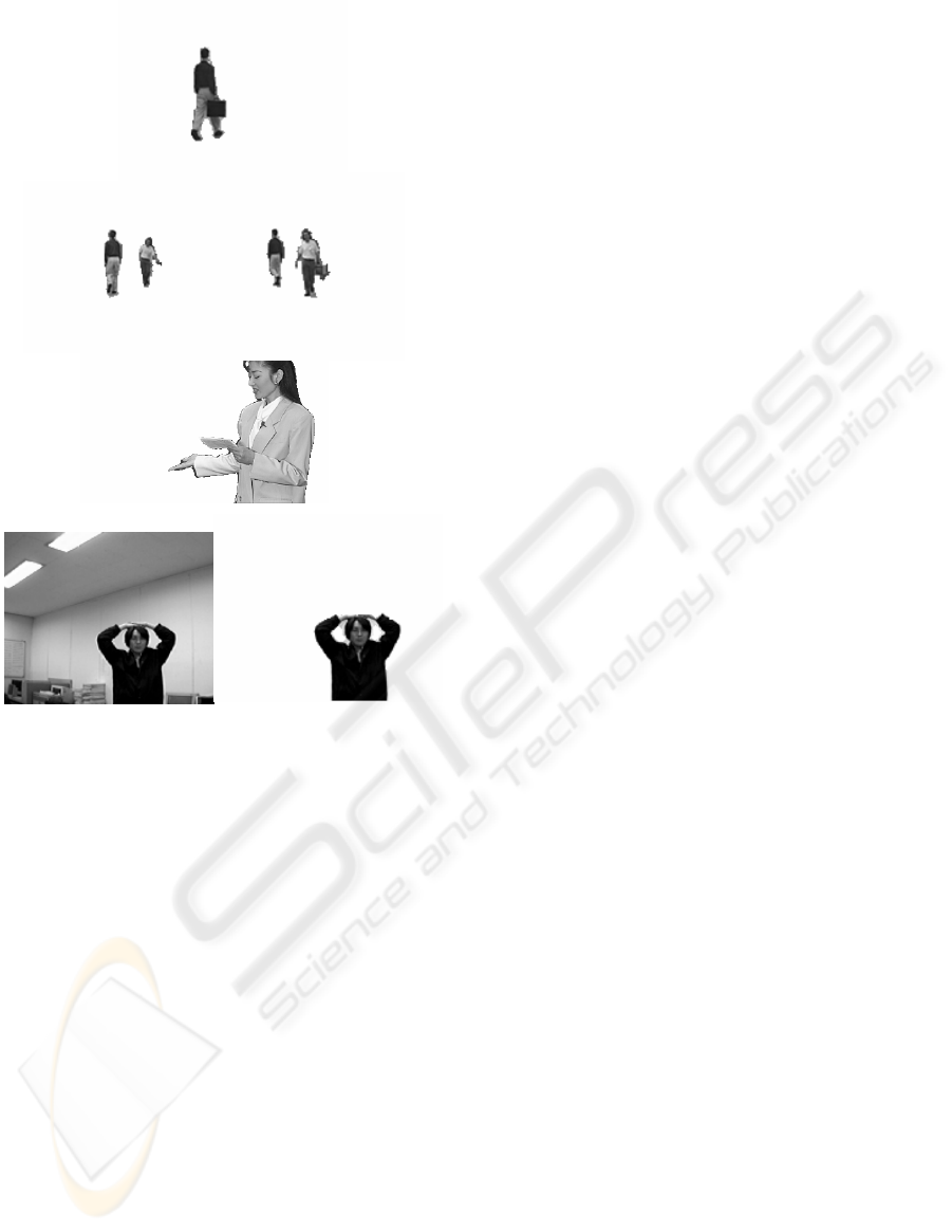
mask of second type. Fig. 13 (a) shows
“Mother&Daughter” which has a wide broken
boundary and (b) shows the segmentation result
using expression (7). Fig. 13 (c) and (d) show the
segmentation of “Junki” real video which has holes
in its region using expression (7), too.
(a) (b)
(c) (d)
Figure 13: Moving object extraction with both masks
(a) Mother&Daughter with a wide broken boundary,
(b) Mother&Daughter segmentation result,
(c) Junki real video A, (d) Junki real video B
2.4.4 Moving cast shadow filtering
The moving cast shadow is composed of a dark
region called umbra and a soft transition region
called penumbra (Stauder,1999). We apply the
Roberts gradient operator to filter out the moving
cast shadow. This shadow filtering operation can be
executed to the input image.
3 EXPERIMENT
We experiment the moving object segmentation
algorithm using the MPEG-4 standard test image
sequences such as “Hall monitor”, “Claire”,
“Akiyo”, “Weather” and “Junki” real video.
3.1 Objective evaluation
We use the error percentage measure (Chien,2002)
for the objective evaluation. The error percentage
measures the cumulative error between the original
image and the segmented image.
(8)
MOVING OBJECTS SEGMENTATION USING BOUNDARY
275

The a(x, y) is the alpha map of the original image
used for reference.
⊕
is the Exclusive-OR
operation. The OM(x, y) is the alpha map of the
segmented image. W is the width and H is the height.
Fig. 14 shows the error percentage graph for
“Claire”, “Akiyo”, and “Weather”.
Figure 14: Error percentage graph
The size of image sequence is CIF(352x288) and
it is input 25 frames/sec. We obtained the a(x, y)
reference image sequence by segmenting it manually
using the PHOTOSHOP tool in order to obtain the
accurate reference image. Also, we obtained the
OM(x, y) by applying the proposed object
segmentation algorithm.
If there is no difference, the error percentage is
0%. If the error percentage is above 1.5%, then the
segmented moving object could show some visually
recognizable difference from the input moving
object.
The error percentage values we obtained from our
experiments are less than 0.78% for these image
sequences. This value indicates that the segmented
moving object by our algorithm is visually very
similar to the manually segmented moving object
frames from the input image sequence and
validates that the proposed segmentation algorithm
can segment the objects very accurately. In Fig. 14,
frames 3 and 4 of “Akiyo” and “Weather” show
some high value of error percentage and frame 49,
79, and 94 of “Claire” show high value of error
percentage because the object moves somewhat
faster in these frames.
We can compare Fig. 14 with Fig. 7 of
(Chien,2002) and can see that the error percentage
results of “Akiyo” and “Weather” of our approach
are comparable with those results.
Table 1 shows the performance statistics of our
algorithm and other approaches for comparison. We
use the P-IV CPU with 2.0GHz as the experiment
CPU. We have optimized the implementation of
computation intensive algorithms to satisfy the real-
time requirement of various multimedia applications.
Table 1: Performance statistics
Table 1 shows the performance statistics. The
table shows the test sequences, total frames, total
processing time, and frames per second. The test
sequences are CIF(352x288) and QCIF(176x144)
standard MPEG-4 test sequences such as “Hall
monitor”, “Akiyo”, “Claire”, “Mother&Daughter”,
and “Weather”. For
example, the proposed system
can process 72.25 frames per second for “Hall
monitor” QCIF sequence, in other words, the system
spends 0.0138 second per frame for “Hall monitor”
QCIF sequence. We have included the performance
results of (Kim,2002),(Chien,2002), and
(Chien,2003) in the table for comparison. The
approach (Chien,2002) can process QCIF at 25 fps
and CIF at 10 fps using P-III 450MHz CPU. The
approach (Chien,2003) can process QCIF at 9.4 fps
using P-III 800MHz. The test CPUs are different but
we can conclude that the proposed algorithms are
more efficient than those algorithms.
3.2 Subjective evaluation
We show the moving object segmentation results of
“Hall monitor”, “Weather(360x243)” in Fig. 15. We
also use “Junki” real video sequence to demonstrate
the segmentation of an object which has holes in its
region.
ICETE 2004 - WIRELESS COMMUNICATION SYSTEMS AND NETWORKS
276
(a1) Hall monitor 45
th
(a2) Hall monitor 152
th
and 219
th
(a) Hall monitor
(b)Weather 217
th
(c) Junki real video 158
th
Figure 15: Moving object segmentation
(a) Hall monitor, (b) Weather, (c) Junki real video
We see that our algorithm can produce the
accurate moving object segmentation and can
segment the multiple moving objects and the object
which has holes in its region using these two
complementary object masks. We can see a small
hole in the upper part of Fig. 15 (b) between the hair
and forehead and also can see two holes in (c)
clearly.
We can compare these segmentation results with
the results in (Kim,2002),(Meier,1999),(Chien,2002),
and (Chien,2003). Our segmentation results are
better than those results in terms of the accuracy of
the segmentation result because we use the object
boundary linking for accuracy. The proposed
segmentation algorithm can segment an object
which has holes in its region as shown in (b) and (c)
in Fig. 15. But none of references demonstrate this.
Particularly, we can see in (d) and (e) of Fig. 9 of
(Chien,2002) that the approach does not segment the
object which has a hole in its region. We can also
compare our “Mother&Daughter” segmentation
results of Fig. 13 (b) with those of Fig. 16 and Fig.
17 of (Chien,2003) and we can see that our results
are better.
4 CONCLUSION
We propose a novel moving object edge construction
algorithm, a space-oriented geometric boundary
linking algorithm, and a segmentation algorithm
using two object masks. We can achieve more
accurate moving object segmentation, multiple
moving objects segmentation, and the segmentation
of an object which has holes in its region using these
algorithms.
We have shown the performance of our proposed
algorithms using standard MPEG-4 test image
sequence and a real video from camera. The
proposed algorithms are very efficient and can
process QCIF image more than 48 fps and CIF image
more than 19 fps in a personal computer for real-time
content-based applications.
REFERENCES
Kim, Changick, Hwang, Jenq-Neng, “Fast and Automatic
Video Object Segmentation and Tracking for Content-
Based Applications,” IEEE Trans. on Circuits and
Systems for Video Technology, Vol. 12, No. 2, pp.122-
129, Feb. 2002.
Meier, Thomas, Ngan, King N., “Video Segmentation for
Content-Based Coding,” IEEE Trans. on Circuits and
Systems for Video Technology, Vol. 9, No. 8, pp.1190-
1203, Dec. 1999.
Chien, Shao-Yi, Ma, Shyh-Yih, Chen, Liang-Gee,
“Efficient Moving Object Segmentation Algorithm
Using Background Registration Technique,” IEEE
Trans. on Circuits and Systems for Video Technology,
Vol. 12, No. 7, pp.577-586, July 2002.
Chien, Shao-Yi, Huang, Yu-Wen, Chen, Liang-Gee,
“Predictive Watershed : A Fast Watershed Algorithm
for Video Segmentation,” IEEE Trans. on Circuits and
Systems for Video Technology, Vol. 13, No. 5, pp.453-
461, May 2003.
Canny, John, “A computational approach to edge
detection,” IEEE Trans. on Pattern Analysis and
Machine Intelligence, Vol. 8, No. 6, pp. 679-698, Nov.
1986.
Aach, T., Kaup, A., Mester, R., “Statistical model-
based change detection in moving video,” Signal
Processing, Vol. 31, pp. 165-180, March 1993.
Stauder, Jürgen, Mech, Roland, Ostermann, Jörn,
“Detection of Moving Cast Shadows,” IEEE Trans. on
Multimedia, Vol. 1, No. 1, pp. 65-76, March 1999.
Gonzalez, Rafael C., Woods Richard E., Digital Image
Processing, Prentice-Hall, Inc., 2002.
Hajjar, Amjad, Chen, Tom, “A VLSI Architecture for
Real-Time Edge Linking,” IEEE Trans. on Pattern
Analysis and Machine Intelligence, Vol. 21, No. 1, pp.
89-94, Jan. 1999.
MOVING OBJECTS SEGMENTATION USING BOUNDARY
277
