
DESCRIBING SOFTWARE-INTENSIVE PROCESS
ARCHITECTURES
USING A UML-BASED ADL
Ilham Alloui, Flavio Oquendo
University of Savoie at Annecy - ESIA - LISTIC Lab
B.P. 806 - 74016 Annecy Cedex - France
Keywords: UML-based notation, UML Profiles for software process architecture, Architecture Description Language
Abstract: Many Architecture Description Languages (ADLs) have b
een proposed in the software architecture
community, with several competing notations, each of them bringing its own body of specification
languages and analysis techniques. The aim of all is to reduce the costs of error detection and repair while
providing adequate abstractions for modelling large software-intensive systems and establishing properties
of interest. However, there now exists a large consensus to standardise on notations and methods for
software analysis and design as standardisation provides an economy of scale that results in various and
better tools, better interoperability between tools, more available developers skilled in using the standard
notation, and lower training costs. Therefore software-intensive process architectures can be relevantly
described using a standard-compliant design notation. Among such notations, the UML modelling language
that on one side makes use of visual notations and on the other side, is an emerging standard software
design language and a starting point for bringing architectural modelling into industrial use. This paper
presents an architecture-centred UML-based notation to describe software process architectures. The
architectural concepts have already been formally defined in an Architecture Description textual Language.
The notation is illustrated by a business-to-business process application. The main contribution of this work
is to show that UML with its large and extensible set of predefined constructs imposes itself as a relevant
candidate to be extended with the necessary architectural concepts and customisation to model software-
intensive processes. The work presented is being developed and validated within the framework of the
ArchWare1 IST 5 ongoing European project.
1
ArchWare Consortium : CPR – Consorzio Pisa Ricerche (Italy), InterUnec/Listic – Université de Savoie (France), Victoria
University of Manchester (UK), ENGINEERING – Ingegneria Informatica S.p.A. (Italy), INRIA – Institut National de
Recherche en Informatique et Automatique (France), THESAME – Mecatronique et Management (France), University
Court of the University of St. Andrews (UK).
1 INTRODUCTION
Software engineering is nowadays moving towards
an architecture-based development where systems
are built by composing components that are often
developed independently from each others.
The main benefits of such an approach is that it
al
lows developers to a large variety of software
products and to reduce time to market. Among
software components are Process-enabled
Components, e.g. business process components, that
are process-sensitive, human-intensive, time
consuming, decentralised and heterogeneous. Those
201
Alloui I. and Oquendo F. (2004).
DESCRIBING SOFTWARE-INTENSIVE PROCESS ARCHITECTURES USING A UML-BASED ADL.
In Proceedings of the Sixth International Conference on Enterprise Information Systems, pages 201-208
DOI: 10.5220/0002597602010208
Copyright
c
SciTePress

must also be considered as the building blocks for
larger software processes and then apprehended
through an architectural view.
With this respect, a number of Architecture
Description Languages (ADLs) have been proposed
in the software architecture community, with several
competing notations, each of them bringing its own
body of specification languages and analysis
techniques (Garlan, 1995), (Garlan et al., 1995),
(Magee and Perry, 1998), (Wolf, 1996). The aim of
all is to reduce the costs of error detection and repair
while providing adequate abstractions for modelling
large software-intensive systems and establishing
properties of interest. However, there now exists a
large consensus to standardise on notations and
methods for software analysis and design as
standardisation provides an economy of scale that
results in various and better tools, better
interoperability between tools, more available
developers skilled in using the standard notation,
and lower training costs. Therefore software-
intensive process architectures can be relevantly
described using a standard-compliant design
notation.
Among such notations, the UML modelling
language UML (OMG, 2001) that on one side makes
use of visual notations (class and object diagrams,
use case diagrams, sequence diagrams, collaboration
diagrams, state-chart diagrams, activity diagrams,
implementation diagrams) and on the other side, is
an emerging standard software design language and
a starting point for bringing architectural modelling
into industrial use. UML provides a large, useful,
and extensible set of predefined constructs and has
the potential for substantial tool support. As such, it
imposes itself as a relevant candidate to be extended
with the necessary architectural concepts and
customisation to model software-intensive
processes.
Our approach is to provide users (i.e. process
designers) with an architecture-centred UML-based
notation to describe software process architectures.
The architectural concepts have already been
formally defined in the ArchWare/ADL textual
language (Oquendo et al., 2002). Thus this paper
presents the ArchWare/ADL UML-based concrete
syntax. Section 2 describes the background and
concepts of ArchWare/AD and explains the
ArchWare/ADL UML-notation. The conclusion
summarises the main contribution of this work and
presents ongoing work.
2 ARCHWARE/ADL UML-BASED
CONCRETE SYNTAX
The ArchWare/ADL is a formal language for
modelling evolvable software architectures . It is
part of the ArchWare Architectural Languages,
which are: (a) the Architecture Description
Language (ADL), (b) the Architecture Analysis
Language (AAL), (c) the Architecture Refinement
Language (ARL), (d) the Architecture eXchange
Language (AXL). In the remaining of this section is
briefly introduced the UML-based concrete syntax
of the ArchWare/ADL. The goal behind the p-ADL
UML concrete syntax is to: (a) provide the users’
with a visual notation dedicated to the software
(process) architecture domain; (b) to support
different stakeholders in an architecture-based
software engineering process (style designers,
software (process) designers, software (process)
developers, software (process) maintainers, etc.).
2.1 UML-based ADL Approach and
concepts
UML as a proven standard notation with powerful
extension mechanisms has been chosen as the basis
for the ADL concrete syntax. Stereotyping is used to
extend a base modelling element by new properties
and restricting it by new constraints: properties are
added by the tagged value mechanism; constraints
are added by a formal language (e.g. OCL). Profiles
are used to define model elements that have been
customised for a specific domain by using UML
stereotypes, tagged definitions, and constraints.
Using such mechanisms, we propose a two-steps
approach in the design of our UML-based concrete
syntax, consisting in the definition of:
– a layered meta-model of the ArchWare/ADL
independent from the UML meta-model;
– the UML profiles for the ADL: (a) mapping the
ADL meta-models to the UML meta-model; (b)
defining appropriate icons.
The first defined profile is that related to the
“component-connector” architectural style. Indeed
architectural styles allowed by the ArchWare/ADL
style mechanisms (Cimpan et al., 2002) are designed
as profiles in the UML-based notation.
2.2 ArchWare/ADL meta-model
The architecture of the UML-based syntax is based
on a two threads layered meta-model structure that
consists of the following layers (see Fig. 1):
ICEIS 2004 - INFORMATION SYSTEMS ANALYSIS AND SPECIFICATION
202
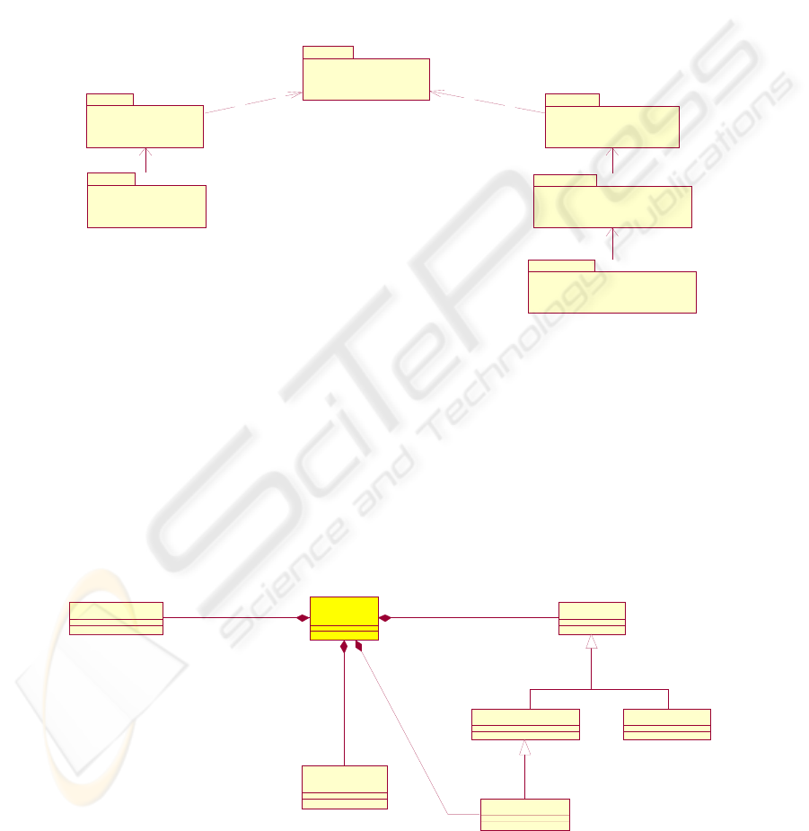
– ADL foundations that defines the language for
specifying the core meta-models to describe
software architectures. Basic data types are
contained in the Data Types sub-package and a
single architectural abstraction Abstraction
Archetype in the Architectural Types sub-
package.
– ADL models: at this layer, users are provided
with a language that allows them to define
architecture models as instances of ADL
foundations meta-models.
– ADL instances: at this layer, ADL models are
instantiated using UML instantiation
mechanisms. Here lay the users’ objects.
– ADL profiles: that extends the ADL foundations
package with style-related architectural
abstractions. For instance the Component and
Connector profile provides the users with the
following abstractions: ports, components,
connectors and composites to describe software
architectures using a “component-connector”
style.
A D L m odels
< <m odel>>
A D L foundations
<<metam odel>>
A D L instances
<<instance>>
C om ponent and
C onnector
<<profile> >
C om ponent and
Connector models
<<m odel>>
C om ponent and
C onnec tor instances
< <instance> >
dependency
de pendency
ins tantiates
instantiates
instantiates
Figure 1: UML-based ADL main packages
Two possibilities are consequently offered to the
users: (a) using the architectural foundations directly
to instantiate models and their instances; (b) using a
profile (e.g. component and connector) to define
models and their instances.
The ADL Foundations contains two sub-
packages: Data Types and Architectural Types. Data
Types contains all data types defined in the ADL,
i.e. usual data types (simple and constructed ones)
plus more specific ones like the connection type and
the behaviour type.
Abstraction
ArcheTy pe
*
formal parameters
Formal Parameter
*
declarations De c lar at ion
Ty pe DeclarationValue Declaration
Connection Ty pe
*
con nections
Behav iour Ty pe
(from D ata Types)
behaviour
0..1
Figure 2: Abstraction archetype meta-model
DESCRIBING SOFTWARE-INTENSIVE PROCESS ARCHITECTURES USING A UML-BASED ADL
203
The main reason for that is that the
ArchWare/ADL is formally founded on the p-
calculus (Milner, 1980), i.e., a process algebra with
the concepts of connection (i.e. interaction point)
and behaviour (i.e. sequences of actions).
Architectural Types contains the concept of
Abstraction Archetype defined by a set of formal
parameters, a set of value and/or type declarations
and at most one behaviour (see Fig. 2). Connection
Type is defined as a value declaration.
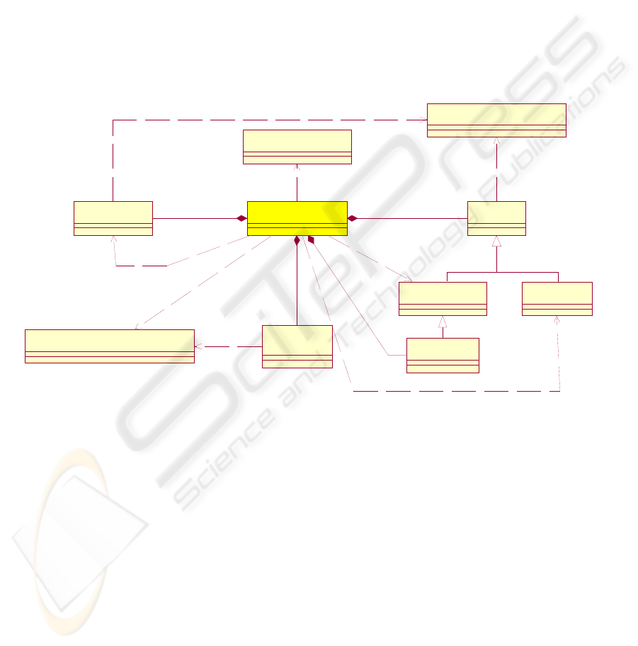
2.3 Profiling architectural style in
UML
The simplest profile we have defined is the
Abstraction Archetype. The mapping between the
ADL meta-model and the UML meta-model is
depicted by Fig. 3. Abstraction Archetype is
stereotype of the UML core Classifier meta-class;
Declaration and Formal Parameter are stereotypes of
the UML core StructuralFeature meta-class;
Behaviour Type is stereotype of UML
State_Machines StateMachine meta-class.
Stereotypes and corresponding tagged values are
shown in Fig. 3.
Ty pe D eclaration
<<ty pe>>
Valu e Declaration
<<v alue>>
C lass if ier (f rom U ML C ore)
<<metaclass>>
StructuralFeature (f rom UML C ore)
<<m etaclass>>
StateMachine (f rom U ML State_Machines)
<<metaclass>>
Declaration
<<s tereot y pe>>
<<stereoty pe>>
Form al Param eter
<<stereoty pe>>
<<stereoty pe>>
Behav iour Ty pe
(from Data Types)
<<stereoty pe>>
<<stereoty pe>>
Con nection Ty pe
<<connection>>
Abstraction ArcheType
<<stereoty pe>>
parameter
<<taggedValue>>
<<stereoty pe>>
value
*
<<taggedValue>>
ty pe
*
<<taggedValue>>
be hav i our
<<taggedValue>>
** **
0. .10. .1
**
Figure 3: Abstract Archetype profile
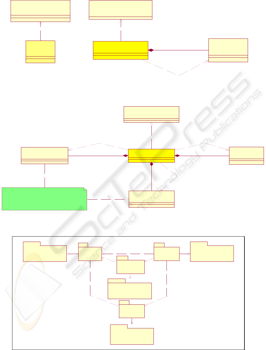
A less simpler profile is that we named
Component and Connector (see Fig. 4 and Fig. 5)
that consists of a set dependent packages related to
the following abstractions: composites, components,
connectors, behaviours, ports. Each abstraction
instance may have zero or one behaviour. All
abstraction instances but ports may have zero, one or
many ports. Within composites, ports may be
connected to each other through unification of their
connections.
Port, Component, Connector and Composite
archetypes are defined themselves as stereotypes of
Abstraction ArcheType with the corresponding
tagged values.
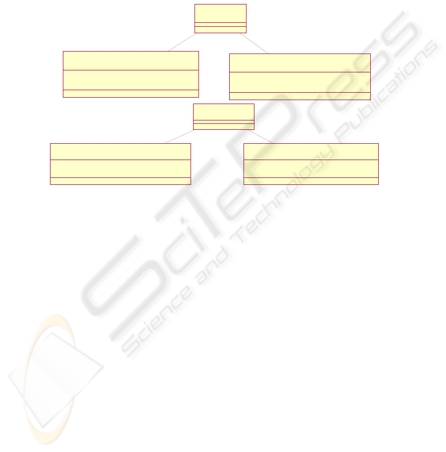
The Component and Connector profile model
packages (i.e. the ADL Models layer) and their
dependencies are depicted by Fig. 6.
ICEIS 2004 - INFORMATION SYSTEMS ANALYSIS AND SPECIFICATION
204
Port
ArcheType
<<stereoty pe>>
<<ste reot y pe>>
Ab straction ArcheType
(from Abstraction ArcheTypes)
<<m etac las s>>
Abstraction ArcheType
(from Abstraction ArcheT ypes)
<<m etac lass >>
Port ArcheTy pe
(from Port ArcheTypes)
<<port>>
C om p onent ArcheTy pe
<<stereoty pe>>
**
ports
<<port m eta-ty pe>>
port
*
<<taggedValue>>
<<stereoty pe>>
Figure 4: Port ArcheType and Component Archetype meta-model
profiles
Abstraction ArcheType
(fr om A bstractio n Arc heT ype s)
<<metaclass >>
C om ponent ArcheTy pe
(from C om ponent ArcheT y pes )
<<com ponent>>
C onnector ArcheTy pe
(from C onnector ArcheT ypes )
<<connector>>
Port ArcheTy pe
(from Port ArcheTypes)
<<port>>
C om p os i te A rc h eT y p e
<<com posite>>
**
components
< <com ponen t met a-ty pe>>
**
conn ecto rs
<<connector m eta-ty pe>>
**
ports
<<port m eta-ty pe>>
W ithin the context of a Com posite:
Com ponents and Connectors
have their ports unified through
port connections unification.
com ponent
*
< < t a g g e dV a lue > >
connector
*
<<taggedValue>>
<<stereoty pe>>
port
*
<<taggedValue>>
Figure 5: Composite ArcheType meta-model profile
Port ArcheTy pe
Model
<<model>>
Port ArcheTy pes
<<metamodel>>
(f rom Component and Connector)
Connector
ArcheTy pe Model
<<m odel>>
Connector ArcheTy pes
<<metamodel>>
(f rom Component and Connector)
C om ponent
ArcheTy pe Model
<<model>>
Com ponen t Arche Ty pes
<<m etam odel>>
(f rom Com ponen t and Connector)
Composite
ArcheTy pe Model
<<m odel>>
Composite ArcheTy pes
<<metamodel>>
(from Component and Connector)
Figure 6: Component and Connector profile model packages
DESCRIBING SOFTWARE-INTENSIVE PROCESS ARCHITECTURES USING A UML-BASED ADL
205
2.4 An illustrating example in the
business process domain
To illustrate our approach, we take a very simple
example of using UML-based ADL concepts and
mechanisms to model business processes. The
software-intensive process of interest is a business-
to-business one that involves enterprises connected
to each other through an IT infrastructure (e.g.
Internet). The enterprises are assumed to have
similar behaviour to achieve their business. Fig. 7
shows the structure of an enterprise’s interface that
defines two port types PortEIn and PortEOut, each
of them is defined by a connection type (resp.
EnterpriseInput and enterpriseOutput) and the type
of data (i.e. Any) that may be sent/received through
the port’s connection. The same approach is taken to
define the IT infrastructure structure.
PortEIn
<<type>> Data = Any
<<value>> enterpriseInput = connection(Data)
<<port>>
Enterpris e
<<com ponent >>
PortEOut
<<type>> Data = Any
<<value>> enterpriseOutput = connection(Data)
<<port>>
IT In fra s tru c tu re
<< connector> >
PortITOut
<<type>> Data = Any
<< value> > itO utput = connection(Data)
<<port>>
P o rt IT In
<<type>> Data = Any
<< value> > itInput = connection(Data)
<< port>>
Figure 7: Enterprise and IT infrastructure structure in UML-based ADL
Fig. 8 depicts an enterprise behaviour type
within a business-to-business process. The state
diagram shows two parallel (composed) and
replicated sub-processes:
a) receiving a request (through enterpriseInput),
taking decision (internal action tau), sending an
answer (accept or refuse through
enterpriseOutput) and ending the sub-process
(done);
b) sending a request (through enterpriseOutput),
receiving an answer (accept or refuse through
enterpriseInput) and ending the sub-process
(done).
Request, Accept and Refuse are sub-types of
Any. Process parallel composition is expressed
through a UML composite state, process replication
is indicated by the stereotype <<replicate>>,
alternative choice is that of UML state machines, the
stereotype <<done>> indicates successful ending of
a process. Transitions are labelled by actions of the
form: via connection_name send typed_data, via
connection_name receive typed_data, tau, [x=y]
<send or receive action>. Further details can be
found in (Alloui and Oquendo, 2003).
ICEIS 2004 - INFORMATION SYSTEMS ANALYSIS AND SPECIFICATION
206
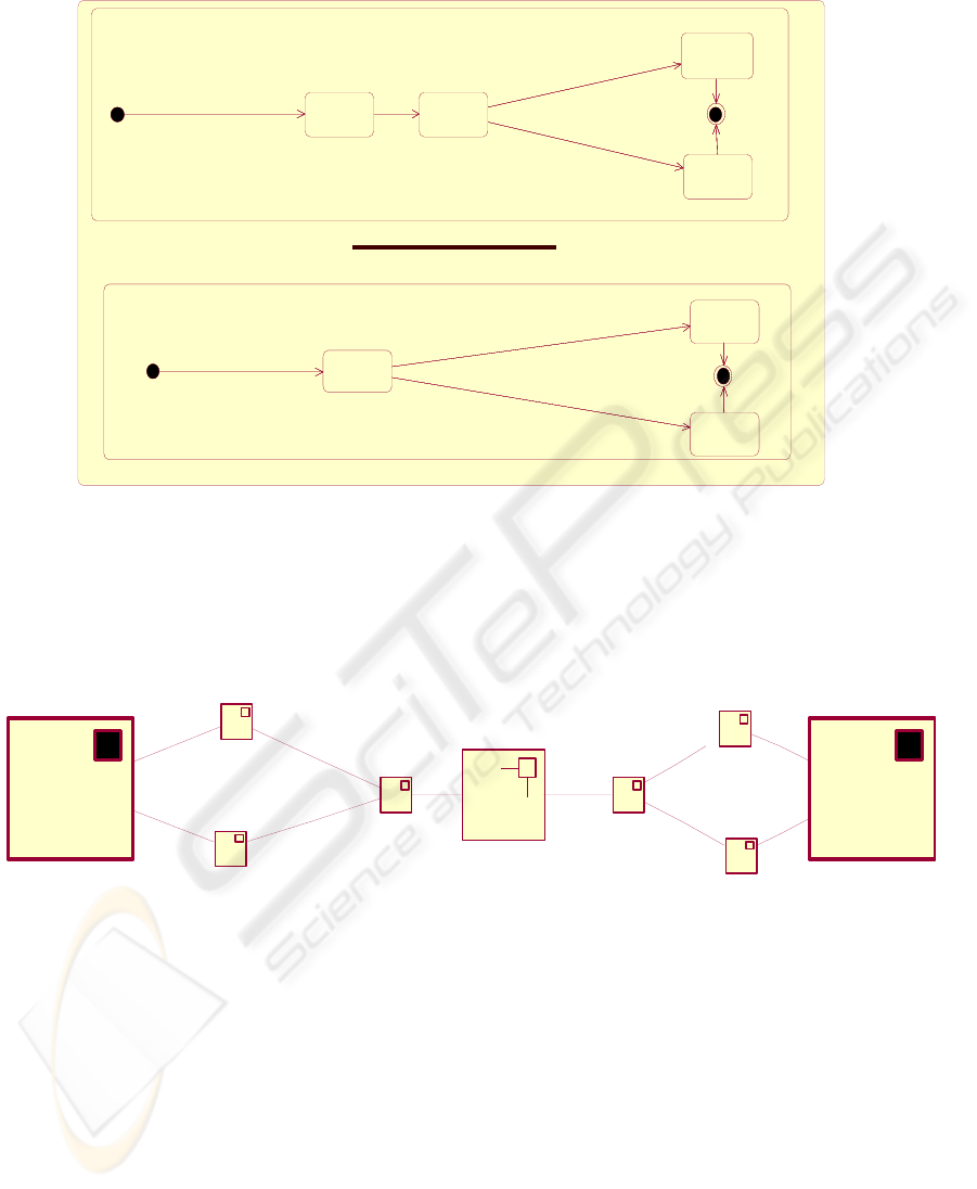
<<done>><<done>>
v ia enterpriseOutput send request : Request
<<replicate>>
via enterpriseInput receive accept: Accept
v ia enterpriseInput receiv e ref use: Ref use
<<done>>
vi a e nter priseI nput recei v e request: Request
<<replicate>>
tau
via ent erpriseOutput send accept: Accept
<<done>>
via enterpriseOutput send refuse: Ref use
Figure 8: Enterprise behaviour type
In addition customised icons have been designed
to represent both models and instances of
composites (e.g. 2E: B2B Composite), components
(e.g. enterprise1), connectors (it), ports (e.g.
:PortEOut) and connections (e.g. enterpriseOutput)
(see Fig. 9).
:PortEOut
enterprise1:Enterprise
it:ITInf rastructure
:PortEIn
enterprise2:Enterpris
e
:PortEOut
:PortITOut
enterpriseInput
enterpriseOutput
:PortEIn
:PortITIn
enterpriseOutput
enterpriseInput
Figure 9: Global structure of a two-enterprises business-to-business process
The composite instance 2E is composed of
enterprises1 and enterprise2 that are connected to
each other through the connector instance it via port
connections. It is worth noting that more customised
icons could easily be designed for the business-to-
business process domain.
3 CONCLUDING REMARKS
This paper briefly presents the use of standard-
compliant architecture description languages to
describe software-intensive processes. The main
contribution of this work is to monstrate that a
UML-based ADL is relevant in the modelling of
both software-intensive process structure and
behaviour. The profiling mechanism is used to
customise UML meta-model for the architectural
domain.
With respect to the assessment of UML
expressive power for modelling software
architectures reported on in (Medvidovic et al.,
2002), our approach meets almost all the
requirements cited by the authors, namely the
structural, stylistic, behavioral and constraints
concerns defined in the ArchWare/ADL. More
precisely constraints in our case are not expressed in
DESCRIBING SOFTWARE-INTENSIVE PROCESS ARCHITECTURES USING A UML-BASED ADL
207

OCL but in ArchWare/AAL (Alloui et al., 2003) that
is supported by a set of tools for architecture
analysis by model checking (behaviour), theorem
proving (structure) and specific evaluation. Our
objective is not the same as those authors as the
proposed notation (a concrete syntax for
ArchWare/ADL) is to be supported by a set of
toolkits and other languages that are not all UML-
based.
Another language that plays the same role as
UML in the sense that it also tends to be a standard
is ACME (Garlan et al., 1997). It is an architecture
interchange language intended to support automatic
transformation of a system modelled in one ADL to
an equivalent model in another ADL. Its
architectural ontology plays a role analogous to
UML meta-model but ACME focuses only on
structural aspects of architectures. Our approach
does not use translation between notations, but it is
rather based on a core model with several
independent extensions that form a basis of an
evolvable, broadly applicable extensions of UML for
process architectural modelling.
This work is currently being implemented and
evaluated within the framework of the ArchWare
IST5 European project. The proposed notation is to
be supported by a toolkit that includes: a (process)
architecture modeller and a (process) architecture
animator. A first prototype has previously been
realised using Rational Rose
(
http://www.rational.com/).
REFERENCES
Garlan, D., 1995. In the First International Workshop on
Architectures for Software Systems (Seattle, WA,
Apr.). Published in ACM Softw. Eng. Notes.
Garlan, D., Paulisch, F.N. and Tichy, W.F, 1995.
Summary of the Dagstuhl Workshop on Software
Architecture,. ACM Softw. Eng. Notes, 63–83.
Magee, J. And Perry, D.E., 1998. In the Third
International Software Architecture Workshop (ISAW-
3), Lake Buena Vista, FL. ACM Press, New York, NY.
Wolf, A.L., 1996. In the Second International Software
Architecture Workshop (ISAW-2), San Francisco, CA.
OMG, 2001. Unified Modeling Language Specification,
Version 1.4.
Oquendo, F., Alloui, I., Cimpan, S. and Verjus, H., 2002.
Definition of the ArchWare/Core ADL and Style-ADL
Abstract Syntax and Formal Semantics. ArchWare
Deliverable D1.1b.
Cimpan, S., Oquendo, F., Balasubramaniam, D., Kirby, G.
and Morrison, R., 2002. ArchWare/Core-ADL and
Style-ADL textual concrete syntaxes. ArchWare
Deliverable D1.2b.
Milner, R., 1980. A Calculus of Communicating Systems.
LNCS 92, Springer-Verlag,.
Alloui, I. and Oquendo, F., 2003. UML ArchWare/Style-
based ADL. ArchWare Deliverable D1.4b.
Medvidovic, N., Rosenblum, D.S., Redmiles, D.F. and
Robbins, J.E., 2002. Modeling Software Architectures
in the Unified Modeling Language. ACM Transactions
on Software Engineering and Methodology, Vol. 11,
No. 1.
Alloui, I., Garavel, H., Mateescu, R. and Oquendo, F.,
2003. The ArchWare Architecture Analysis Language.
ArchWare Deliverable D3.1b.
Garlan, D., Monroe, R., and Wile, D., 1997. ACME: An
architectural interconnection language. In CASCON
’97 (Toronto, Ont., Canada). IBM Canada Ltd.,
Toronto, Ont., Canada.
ICEIS 2004 - INFORMATION SYSTEMS ANALYSIS AND SPECIFICATION
208
