
AN AUTOMATION SYSTEM BASED ON LABVIEW TO
CONTROL THE TEST OF MECHANICAL FLOW METERS
Mechanism to characterize flow measurers
Javier Martínez (1), Ricardo Alvarez (3), Petronilo Cortez (4), Víctor Mejia (5)
Mexican Institute of Water Technology (IMTA) Paseo Cuauhnahuac No. 8532,Cuernavaca, Morelos,
México:
Victor Hugo Zárate Silva(2)
Institute Tecnologico and of Superior Studies of Monterrey - Campus Morelos,
Mexico: victor hugo zarate silva.
Abstract: A mechanical flow meter is a device used mainly to measure and calculates velocity of weater´s
flow on rivers and open channels. These devices, as the time of use pass trough, suffer
mechanical imperfections, that are why it is important to calibrate them twice a year, depending
of its time of use. At the Mexican Institute of Water Technology (IMTA in Spanish) was
designed and developed a circular water tank for propose of test of these meters. The present
paper shows the automation systems designed to control the tests to calibrate these mechanical
meters. The system is based on LabVIEW. LabVIEW is a general purpose programming tool
with extensive libraries for data acquisition instrument control, data analysis, and data
presentation. With this tool and a special hardware interface, it was possible to automate the
process to test these meters. The system is called SCM (System of characterization of
mechanical meters). SCM control the test of two mechanical meters simultaneously, and has
some user's control features that permit the Operator a easy to use human machine interface.
1 INTRODUCTION
Before that disappear the installation where
himself towards the Calibration of the mechanical
meter flow the Mexican institute Technology water
builds a circular water tank for purpose apart the
test calibration those meters.
This circular water tank have 12m of diameter,
80cm
. Cross section and 1.40m of depth with a
motor is of 15 kV. for move the arm of 12m the
mechanical flow meter are device use for
Measurement the speed in river and open channel,
the which testing needs depending on your use.
This measurements it are carry with the help of
a hea
dphone and a battery, himself submerge the
device in the water flow and himself count the turn
that get your cops a the open or close a circuit each
revolution in a period of time give and with this
date and know the area is possible calculate the
expense.
In the channel in the beginning himself
produce
r the characterizations in form manual:
before the apocopated demand, himself use the
tool the computation for produces the
characterizations of the measurement of flow.
2 PERIPHERY AT CONSIDERS.
For carry at handle the development of software
was necessary take in count the information that
drive each a of the mechanics, list the parts that
will be in the system and in consequence define the
software.
CONCEPT
a) The measurement flow are system mechanics
of m
easurement of flow of water, consist of a
system of six cones or cup, the as are impulse
for the flow of water.
In of mechanism have platinum that himself close
for each t
our complete that gives the disc o cups.
530
Martínez J., Hugo Zárate Silva V., Alvarez R., Cortez P. and Mejia V. (2004).
AN AUTOMATION SYSTEM BASED ON LABVIEW TO CONTROL THE TEST OF MECHANICAL FLOW METERS - Mechanism to characterize flow
measurers.
In Proceedings of the Sixth International Conference on Enterprise Information Systems, pages 530-535
DOI: 10.5220/0002607705300535
Copyright
c
SciTePress
Given himself mechanics character, each flow
meter has himself proper characterization of
answer.
b) The signal of the flow meter is transmitter
since the arms towards the smallhouse of
control for means of brush location in the axis
central.
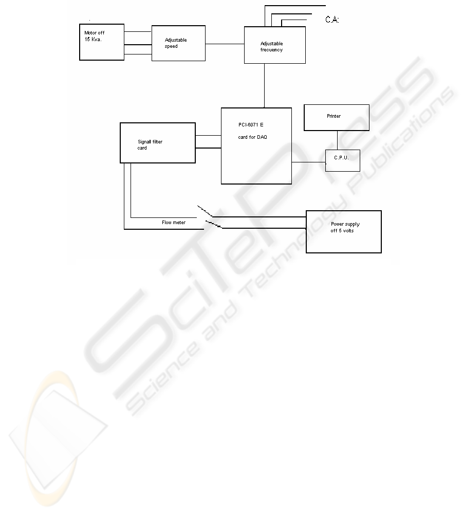
In the fig.1 himself see the complete system.
Fi
g
ure 1: Draw of com
p
lot of circular water tank s
y
ste
m
COMPONENT IN THE SYSTEM
1. PCI-6071 E card for DAQ
2. - Adjustable frequency ABB
3. -Pentium II 400mhz computer
4, -Signal filter card
5. -Power supply
6. -Flow meter
7. -Engine of 15 kV.
8. -Adjustable speed
9.-Software LabView
Himself make a description for each
component.
1. - PCI-6071 E card for DAQ
This is E Series multifunction DAQ I/O, it can
solve DAQ and control system applications,
automatization, programmable input ranges and
gains where determinism in your software is
critical.
The E series not only do you have the
flexibility to easily port your applications between
different computer platforms and operating
systems.
This is install in of the PC and it is possible
configure for software and the connection of
jumper according this conditions that the person
want.
This hardware has libraries for facilitate the
communications with the instrument that are
necessary for measurement the signals.
2. - Adjustable frequency ABB.
The controlador of C.A. of 1 to 75 HP count
with a display and at keys for control the panel,
also with a menu where is optional the drive, in
form manual and automatic.
A bridge of diodes converts line power almost
entirely to active power. The displacement power
factor approaches unity (>0.98) regardless of speed
or load of the connected motors.
A Motor control Card controls the Inverter the
Stage and monitors the operation of the ACS 501.
A Control Interface Card is the link between
the operator and the ACS 501. It features a Control
Panel with an alphanumeric display and keypad. A
terminal block for external control connections is
also located on the Control Interface Card.
AN AUTOMATION SYSTEM BASED ON LABVIEW TO CONTROL THE TEST OF MECHANICAL FLOW
METERS: Mechanism to characterize flow measurers
531
The Control Interface Card is optically isolated
from the line potential. The Control Interface Card
common is connected to the chassis ground
through 10-megohm resistor.
2.3. - Pentium IV 400mhz computer.
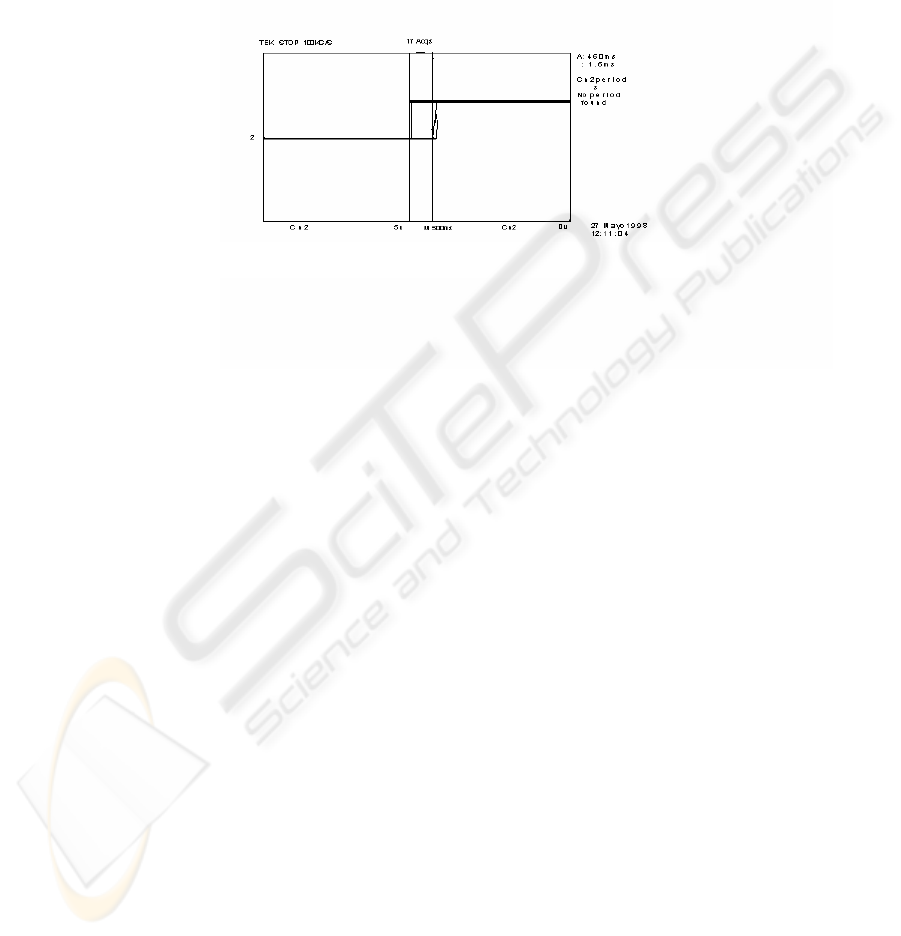
2.4. - Signal filter card.
The signal of the flow meter is very noise how
you look in the fig. 2. For this problem was
necessary place a filter card and a protection at the
circuit by means of an optoisolator circuit.
Fi
g
ure 2: Noise si
g
nal of the flow mete
r
2.5. -Power supplies of 5 volts to 0.5 amperes
for supply the signal to the flow meter.
2.6. -Adjustable speed is manufacture by means
of gears that receive the move of motor of 15 kV.
3 REQUEST OF THE PROGRAM
3.1 Ask identification.
3.2 Menu with options
Characterizations
Consulting base of dates
Get of low or high dates
Recorder each characterizations
3.3 Made the process of characterizations and filter
signal
3.4 Made the calculate necessary.
3.5 Proportion the equation of characterizations.
3.6 Result
- Date of the user
- Graphic of the result
- Table for calculates for in form normal and
with cable
The program himself fulfill in the software
LabView consist in approximately 64 routine, he
model the draw of the program in the fig.3.
A of the screen that us present is the following:
ICEIS 2004 - DATABASES AND INFORMATION SYSTEMS INTEGRATION
532
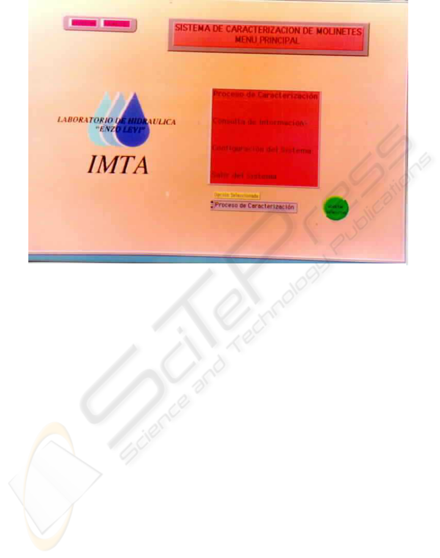
Fi
g
ure 3: Menu Princi
p
al
MENU PRINCIPAL
1. - Process Characterizations.
2. - Consulting base of dates.
3. - Configuration of the system.
4. - Exit of the system.
1. - Process Characterizations in where himself
the assign clef and register number.
a). - Himself into to base of dates, where himself
can select the file of a flow meter with
Characterizations or himself can give of high
or down.
b). - Himself write the dates of the new flow meter
and dates of maintenance date ingress.
c). The system give a screen for actuality the dates
of the equation of adjustment whit the 12
ranges of speed number of test and how many
time last the process.
d). The system question if have other flow meter if
is “no” following to the screen where sample
the information.
e). The process begins actuality of dates of number
of pulse in the ranges of speed in m/sec. That
is 0.148, 0.402, 0.530, 0.657, 0.912, 1.167,
1.422, 1,676, 1.931, 2.186, 2.441 and 2.996.
AN AUTOMATION SYSTEM BASED ON LABVIEW TO CONTROL THE TEST OF MECHANICAL FLOW
METERS: Mechanism to characterize flow measurers
533
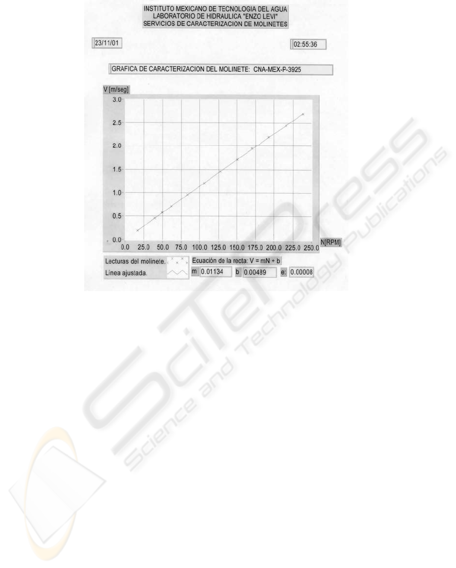
Figure 4: Graphic of characterization of the meter flow
f). When the process finishes himself the can
printer the result in four pages.
1ª. Dates of the user, maintenance and responsible
name.
2ª. Dates of the parameter of equation (m) and (b)
and the graphic that is simple in fig. 4.
3ª Table for gauging in forms normal.
4ª, Table for gauging with cable
2. - Consulting base of dates.
Himself can possible see dates of the flow
meter characterization and edit or print the
information.
3. - Configuration of the system.
Himself can change dates of operation for
example ranges speed, time of advice of error (*).
4. - Exit of the system is when finish all the
process.
* When the flow meter have a problem the
system give signal say “The flow meter doesn’t
ask”
4 CONCLUSION
The development of this software is an innovation
of the technology for characterizes flow meter in
short time and with exact and certain.
With this him comply the objet of achievement
characterizations meter in short time and with
exact and certain.
This mean for fulfill the characterizations for
mean of the characterizations
For mean of the circular water isn’t common,
without embargo the result
Himself compared with characterizations of a
laboratory certify internationally who
Himself is the Laboratory of Canada Center for
Inland Waters obtaining similar results.
By him that can say that this software is
working in of the conditions acceptable.
For him that himself handled of achieve the
certify of all the system.
The operation and maintenance of the software
is easy and rapids.
With the base of dates is possible make
analysis and statistical and with this,
Obtain conclusions for make better the
constructions of the flow meter.
ICEIS 2004 - DATABASES AND INFORMATION SYSTEMS INTEGRATION
534
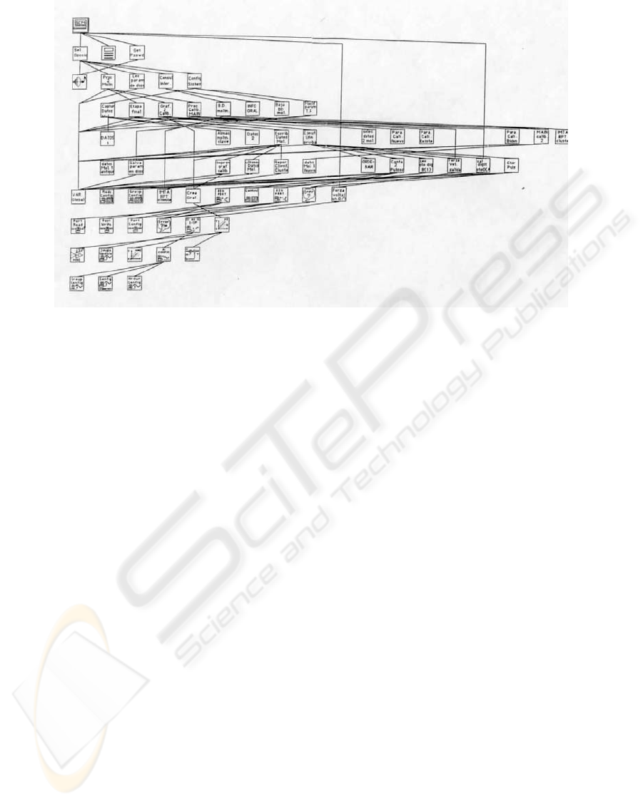
Fi
g
ure 3: Schematic of the software develo
p
ed for make characterizations in the Circular water tan
k
BIBLIOGRAPHY
PIC Usar manual of national instruments
ABB Adjustable frequency. Installation & start-up
Manual
Congreso instrumentación SOMI XII OCT-1998
AN AUTOMATION SYSTEM BASED ON LABVIEW TO CONTROL THE TEST OF MECHANICAL FLOW
METERS: Mechanism to characterize flow measurers
535
