FACE PATTERN DETECTION
An approach using neural networks
Adriano Martins Moutinho, Antonio Carlos Gay Thomé
Núcleo de Computação Eletrônica, Universidade Federal do Rio de Janeiro, Rio de Janeiro,Brasil
Luiz Biondi Neto, Pedro Henrique Gouvêa Coelho
Faculdade de Engenharia, Universidade do Estado do Rio de Janeiro, Rio de Janeiro, Brasil.
Keywords: Face detection, neural networks, image processing.
Abstract: Security systems based on face recognition often have to deal with the problem of finding and segmenting
the region of the face, containing nose, mouth and eyes, from the rest of the objects in the image. Finding
the right position of a face is a part of any automatic identity recognition system, and it is, by itself, a very
complex problem to solve, normally being handled separately. This paper describes an approach, using arti-
ficial neural networks (ANN), to find the correct position and separate the face from the background. In
order to accomplish this goal, a windowing method was created and combined with several image pre-
processing steps, from histogram equalization to illumination correction, as an attempt to improve neural
network recognition capability. This paper also proposes methods to segment facial features such as mouth,
nose and eyes. Finally, the system is tested using 400 images and the performance of face and facial features
segmentation is presented.
1 INTRODUCTION
The human face, in this paper, is defined as the
smallest rectangle that contains the mouth, nose and
eyes of the person, in such way that it is possible to
separate these elements from the other objects in the
image.
Figure 1 illustrates an example of face segmen-
tation as it is defined here. This is a very difficult
task and in order to succeed, any face detection
system must be able to handle several problems like
presence of beard, mustache, skin color variations,
head inclination and face rotation.
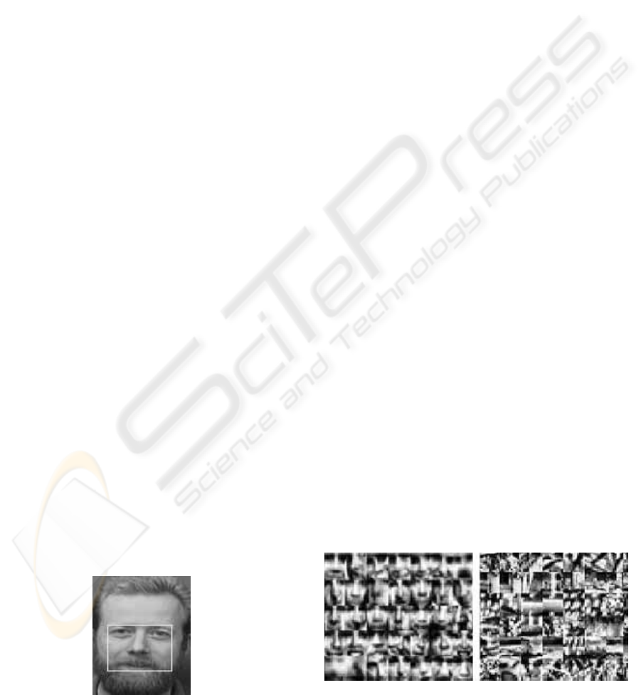
Figure 1: Face example
One of the objectives in this research is to make
the system, as much as possible, immune to these
variations.
The human frontal face, as defined in figure 1,
.is a very distinguished pattern, making the MLP
neural network (Haykin, 1999) a nice choice to
achieve good results. A neural network could be
trained using several sequences of face images, as
shown in figure 2, and many other non-face images
containing geometric shapes, noise and variations
(Rowley, 1999).
Figure 2 shows examples of face and non-face
databases (Rowley, 1999):
Figure 2: Face (left) and non-face (right) database (Row-
ley, 1999)
172
Martins Moutinho A., Carlos Gay Thomé A., Biondi Neto L. and Henrique Gouvêa Coelho P. (2004).
FACE PATTERN DETECTION - An approach using neural networks.
In Proceedings of the Sixth International Conference on Enterprise Information Systems, pages 172-177
DOI: 10.5220/0002610301720177
Copyright
c
SciTePress
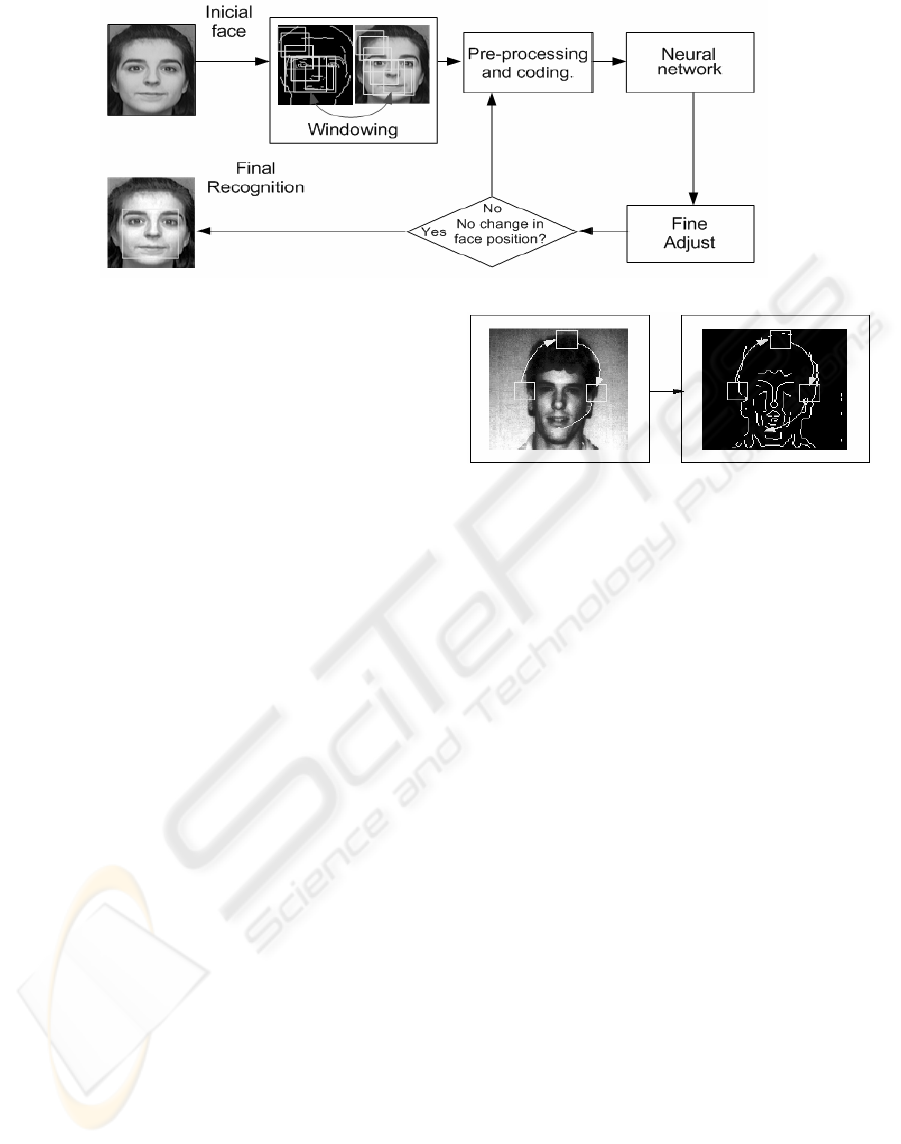
Figure 3: System general view
2 FACE DETECTION SYSTEM, A
GENERAL VIEW
The proposed face segmentation can be divided into
four main modules, as shown in figure 3.
The first module, called windowing, splits the
main picture into squared 19x19 sized sub-images
using an edge seek method, as described in section
3; the second module, called image preprocessing
and coding, described in section 4, prepares the
image signal to improve ANN generalization. Sev-
eral processing steps such as contrast stretch and
illumination correction are applied; the third module
corresponds to an MLP neural network, trained
using databases such as the ones in figure 2. All the
sub-images identified as faces by the ANN are
passed to the fourth module, where face framing is
optimized using a recursive process, in order to
obtain the smallest rectangle that contains the face,
according to the definition presented in section 1.
These adjustments are further described in section 5.
3 WINDOWING
As long as any part of the image, independently of
size or proportion, could contain the desired face,
the windowing module must extract from the origi-
nal image, every possible and distinct rectangular
sub-images, sending them all to the pre-processing
module and then to the neural network, trained to
recognize face patterns. Although this method is
theoretically possible, it would require too much
processing time, because even from a small image
would be possible to extract various distinct sub-
images.
The method suggested in this paper seeks for
faces only around image edges, extracting only sub-
images that contain at least one edge pixel. Figure 4
shows an example of this process. It can be clearly
observed that a face will always contain edge pixels.
Figure 4: Edge windowing example
Even so, the number of distinct images could be
very high. A solution to that would be to first con-
sider the sub-images as a square, not as a rectangle,
and only in a fine adjustment, as described in section
5, it will be optimized to better encompass the face.
After windowing, every extracted image is re-
sized to 19x19 and passed to the preprocessing
module, described in section 4. The windowing
method first computes edge points in the image and
assembles them in a sorted list (according to its
distance to the origin). Then, an adjustable square,
initially 19x19 sized, is centered on the first point in
the list and extracts a sub-image.
4 IMAGE PRE-PROCESSING AND
CODING
In order to obtain a good generalization, it is neces-
sary to do some processing before applying the
signal to the ANN. In the specific case of face pat-
tern detection, it is important to apply a process that
emphasizes the differences between faces and non-
faces images (Rowley, 1999).
Thus, a sequence of transforms is applied, in-
cluding histogram equalization (Gonzalez, 1992),
oval filtering, and illumination correction, as shown
in figure 5.
FACE PATTERN DETECTION - An approach using neural networks
173
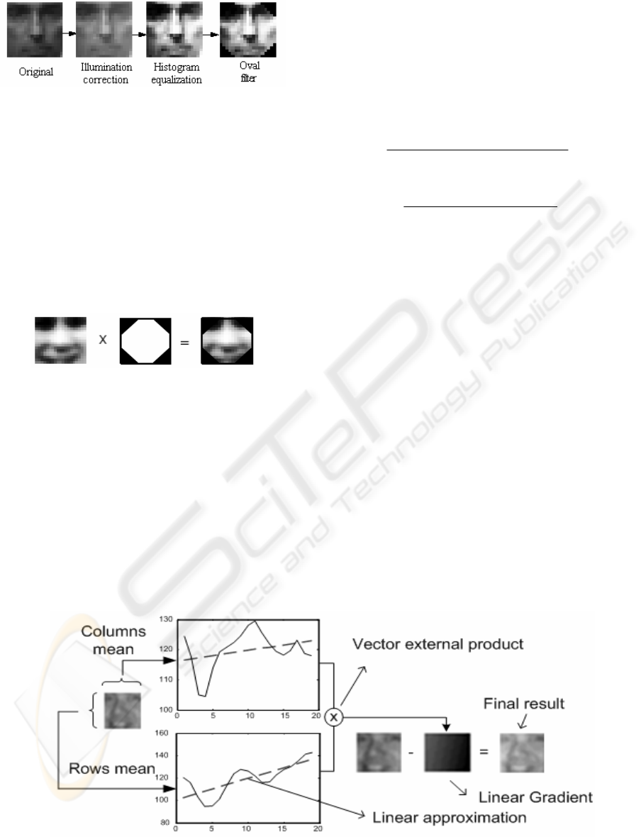
Figure 5: Preprocessing steps, order of application
The histogram equalization is applied following
the traditional methods (Gonzalez, 1992), its objec-
tive is to raise image contrast.
The oval filter follows the principle that pixels
in the borders of face images do not contain relevant
information and could be masked, this operation
does not change a face to a non-face, or vice-versa
(Rowley, 1999). This mask allows the network,
during the training process, to avoid consider such
points, which tend to favor generalization.
Pixel elimination is done by adjusting triangular
masks to the sides of a face, as shown in figure 6.
Figure 6: An oval filter example
Illumination correction is the key point to a reli-
able recognition. It is designed to remove the effect
of regular illumination.
If light effect is presumed to be a linear func-
tion, an image where some illumination is applied
could be decomposed into a linear gradient and a
non-illuminated image. To find this gradient directly
from an already illuminated image, a method is
proposed where the mean of grayscale values of
both columns and rows of an image is calculated.
So, a vector of all row means and a vector of
columns means are build. Linear approximations of
these vectors are computed using the minimum
square method, shown in equations 1, 2 and 3. The
Linear equation is
z
aw
b
=+, where z is the mean
of grayscale values, w is the column or row number
and a and b are the linear coefficients of the ap-
proximation. Figure 7 shows a practical example of
this process.
bawz +≅
(1)
2
22
()
z
www
z
b
zw w
⋅−⋅⋅
=
⋅−
∑
∑∑∑
∑∑
(2)
22
(
)
z
wz w
z
a
zw w
⋅⋅−⋅
=
⋅−
∑
∑∑
∑∑
(3)
The next step is to build a matrix with character-
istics extracted from the image. This process is
called coding, where the lines of the pre-processed
image are concatenated creating a matrix containing
all face examples. The next step is subject the matrix
to a statistic method called principal components
analysis (PCA) (Haykin, 1999), (Johnson, 1998).
The PCA method applies a linear transformation
to the subspace and removes those dimensions with
low variance. It can reduce the size of a training
vector without losing much information. PCA appli-
cation (Haykin, 1999) (Johnson, 1998) results in a
size reduced vector and a transformation matrix,
used to map new data into the same reduced form. In
this paper, the computation of the transform matrix
is done using only the face database, as shown in
figure 2.
The best neural network configuration has one
hidden layer with around 150 neurons. The activa-
tion function is hyperbolic-tangent for the hidden
layer and sigmoid for the output layer.
Figure 7: Illumination correction method
ICEIS 2004 - ARTIFICIAL INTELLIGENCE AND DECISION SUPPORT SYSTEMS
174
Figure 8: Centroid and Successive comparison reduction
5 FINE ADJUSTMENT
The recognition method proposed here tends to iden-
tify the same face several times, on adjacent squares,
as shown in figure 8.
However, this cannot be considered as a disad-
vantage, since all these multiple detections can be
used to validate and find the correct face position
through a process called Centroid Reduction.
Let rectangles A and B be called “Centroid
neighbors” if the centroid of A is within rectangle B
and vice-versa. This definition can be extended to n
rectangles. Figure 8 shows many centroid neighbors,
shown in yellow color.
The centroid reduction method replaces all
“centroid neighbors” by the average square. Squares
that do not have any neighbors are ignored because
they are more likely to be a mistake made by the
ANN. Figure 8 shows an example of centroid reduc-
tion. All yellow squares are replaced by another one
that is computed using the average. The red square
in figure 8 is ignored during the process because it
does not have any “centroid neighbors”.
After centroid reduction, another fine adjust-
ment is made. It is called successive comparison
reduction. From the face position that is the output
of centroid reduction, other faces are generated by
shifting the original rectangle shape one pixel to the
left, right, bottom and top. Other faces are also cre-
ated from the original one, having one pixel width
and height less. All of these faces along with the
original image are again submitted to the neural
network, in a greedy search recursive process, where
the actual face is the higher output value of the neu-
ral network. This process repeats itself until there is
no change in rectangle position between two phases.
Figure 8 also shows the successive comparison ad-
justment method. The result rectangle is smaller and
more adapted to the face than the input square.
6 FACE ELEMENTS
LOCALIZATION
Once the face is located, simple techniques can be
developed to find each face element of the subject.
This is possible because if the smallest rectangle that
contains the face is known, it can be said that all
face elements respect a specific geometry that helps
the task of finding every sub-part of face, such as
eyes, mouth and nose.
6.1 Eye pattern localization
With the smallest rectangle that covers the face, it is
possible to guarantee that the eyes are on the supe-
rior half of this rectangle. It is also possible to admit
that if this superior part is again divided in two
halves, one will be very likely to contain the left eye
and the other the right one.
So, to obtain the right position of both eyes, 2d
cross correlation between the right and left halves
and an eye standard pattern are computed. Equation
4 shows the cross correlation function where M and
N are the dimensions of the picture. Figure 9 shows
the eye pattern.
11
00
1
(
)() ()(
)
MN
mn
fxy gxy fxygx my n
MN
−−
==
,∗ , = , +,+
∑∑
(4)
Figure 9: Eye pattern
Thus, eye masks are generated admitting an
80% tolerance of the maximum correlation value.
When both masks are computed, final eyes positions
are obtained. Figure 10 represents the process, and
figure 11 shows the positions computed.
6.2 Mouth pattern localization
Mouth can be easier identified than eyes. First, the
original face rectangle is divided horizontally. Then,
the mouth’s edges are computed using a Laplacian
method (Gonzalez, 1992) showed in equation 5:
22
2
22
() () ()
fxy fxy fx
y
xy
∂∂
,= ,+ ,
∂∂
"
(5)
Edges on the lateral sides of the image are ig-
nored and a fill algorithm is applied. This
morphological algorithm changes black points into
white when all pixels in D8 neighborhood are white
(Gonzalez, 1992), this process repeats itself up to the
point where no change occurs in the image.
FACE PATTERN DETECTION - An approach using neural networks
175
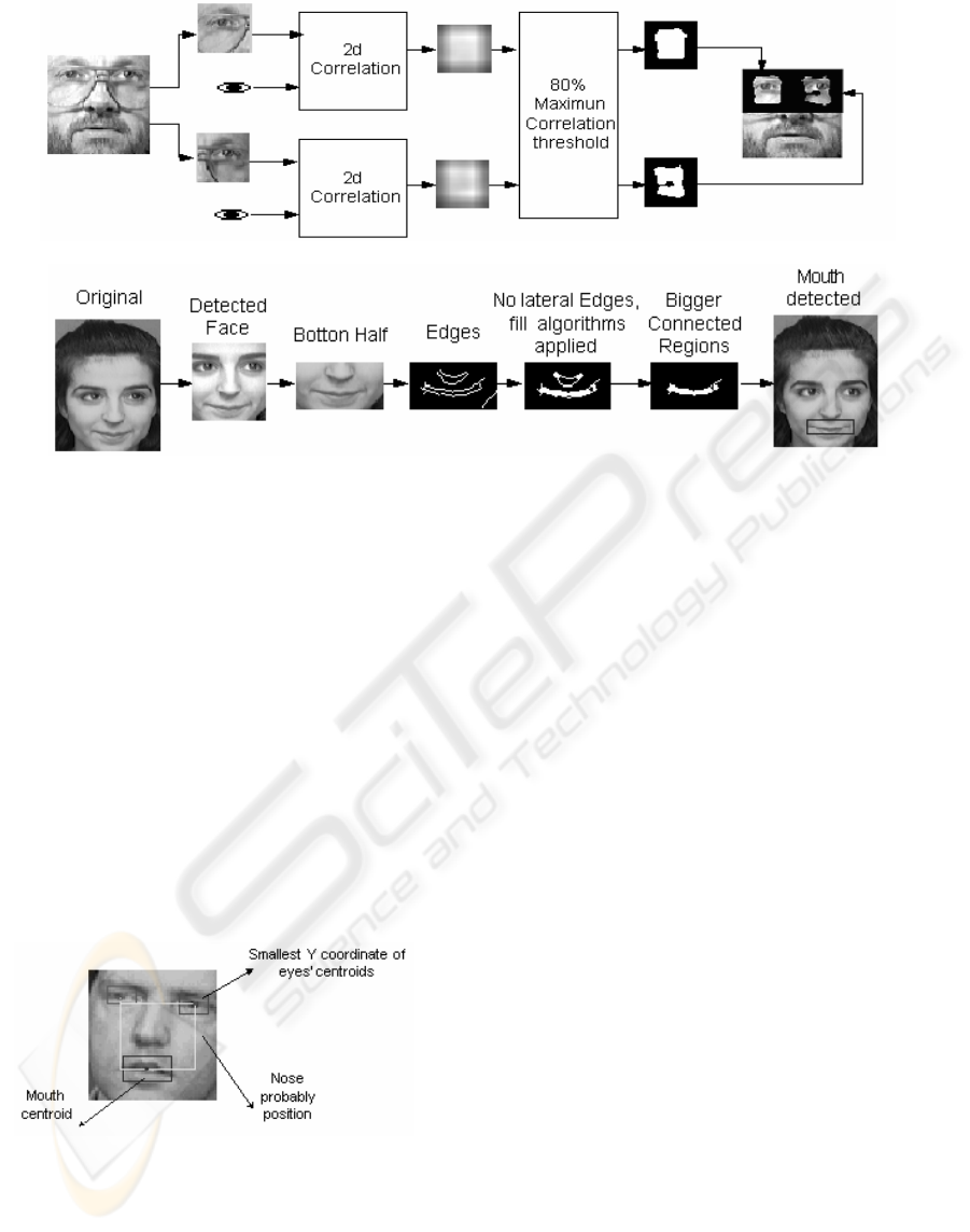
Figure 10: Cross correlation Method and final eyes position
Figure 11: Mouth segmentation method
Finally, if the bigger connected region is ex-
tracted, it will very likely to be the mouth, as shown
in figure 11.
6.3 Nose pattern localization
Although mouth and eyes detection could be done
independently, nose position would be very difficult
to be found without the eyes and mouth information.
This happens because the nose usually does not have
detectable borders and is not, in general, darker or
brighter than the rest of the face.
However, if eye and mouth positions are
known, it is very likely that nose will be located
inside the rectangle defined by the centroids of both
eyes, mouth, and the lowest coordinate of eyes cen-
troid, as shown in figure 12.
Figure 12: Nose position.
From this region, the nose is segmented using
the same method of mouth detection of section 6.2,
by eliminating lateral edges and looking for the
bigger connected region filled by an morphological
algorithm.
7 RESULTS
With face localization methods described in sections
3, 4, 5 and face elements localization methods, de-
scribed in sections 6.1, 6.2 and 6.3; it is possible to
build a face pattern finder.
Using this pattern finder, 400 pattern-tests are
made using the faces available at the AT&T labora-
tory page (AT&T, 2003). Although the focal
distance variance among the faces is very small in
this database, it presents some other important chal-
lenges such as the presence of many non-frontal
poses and rotated faces.
Preliminary results, shown in table 1, indicate
that the most difficult task is nose identification,
because it has neither borders nor different colors
from the rest of the face elements, and it is also very
affected by the presence of glasses, beard or mus-
taches.
A comparison between the method present here
and two other are also shown in table 1:
The first one uses a spikenet to detect face pat-
terns (Van Rullen, 2001). The database used was the
same, but has been separated in test and train sets,
table 1 shows both results.
The Second one uses a Kiosk System (Mãkinen
et al, 2002) to detect face features, only frontal and
non-rotated faces were used.
Figure 13 shows various outputs from the sys-
tem. Face detection is shown in yellow; mouth
position in blue, eyes in red and finally nose in
white.
ICEIS 2004 - ARTIFICIAL INTELLIGENCE AND DECISION SUPPORT SYSTEMS
176

Figure 13: Results of the Face pattern recognition system
Table 1: Preliminary comparative Results
Success rate
Element
Localization
Methods
This paper
(spikenet, 2001)
1
(Mãkinen et al, 2002)
2
Face Preprocessing, Illumination correction and ANN.
90% 88% 92%
Eyes 2d correlation with eyes pattern. 83% 90% 83%
Nose Edge detection and connected regions. 68% Not available 72%
Mouth Edge detection and connected regions. 86% 91% 47%
1
The same database (AT&T, 2003) was used as a training and test set, training set results are shown here.
2
Only frontal and non-rotated faces were used in these results.
8 CONCLUSIONS AND FUTURE
WORK
Results demonstrated on table 1 and figure 13 are
promising. Localization of eyes, mouth and face are
relatively well accurate, but nose position is quite
difficult to find because there are almost no features
that separates it from the background.
Face identity recognition systems can be im-
plemented using face localization methods shown
here. If face position is known, eyes and mouth
position can be found and used to adjust the orienta-
tion of the image. A new set of features can now be
extracted from these parts and used to feed another
neural network model trained to identify the owner
of the face.
New studies are being developed using the face
detection system presented in this paper. Then, it
will be possible to enhance detection process speed
and accurateness, in order to become a part of an-
other identity recognition system.
REFERENCES
Haykin, S., 1999. Neural Networks, a comprehensive
Foundation, 2
nd
edition. Prentice Hall Press, New Jer-
sey.
Rowley, H., 1999. Neural Network-Based Face Detection.
School of Computer Science, Computer Science De-
partment, Carnegie Mellon University Pittsburgh.
Gonzalez, R. C., 1992. Digital Image Processing, Addi-
son-Wesley.
Zurada, J. M., 1992. Introduction to Artificial Neural
Systems, West Publishing Company, New York.
AT&T, 2003. AT&T Laboratories, Cambridge University
Engineering Department, Cambridge,
http://www.uk.research.att.com.
Johnson, R. 1998. Applied Multivariate Statistical Analy-
sis, Prentice-Hall, EUA, 1998.
Demuth, H. and Beale M. 2001. Neural Network Matlab
Toolbox, user’s guide. MathWorks, Inc.
Warren, S. 2001. Internet Neural Network
FAQ.ftp://ftp.sas.com/pub/neural/FAQ.html. Copy-
right 1997, 1998, 1999, 2000, 2001 by Warren S.
Sarle, Cary, NC, USA, 2001.
Mäkinen et al, 2002. Real-Time Face Detection for Kiosk
Interfaces. Unit for Computer-Human Interaction
(TAUCHI) Department of Computer and Information
Sciences FIN-33014 University of Tampere, Finland.
Van Rullen, 2002. FACE PROCESSING USING ONE
SPIKE PER NEURONE. Centre de Recherche
Cerveau & Cognition, UMR 5549, 133 route de Nar-
bonne, 31062 Toulouse, France.
FACE PATTERN DETECTION - An approach using neural networks
177
