
A TOOL INTEGRATION WORKBENCH
FOR ENTERPRISE ARCHITECTURE
Integrating heterogeneous models and tools
Diederik van Leeuwen, Hugo ter Doest, Marc Lankhorst
Telematica Instituut, P.O. Box 589, 7500 AN, Enschede, The Netherlands
Keywords: Enterprise architecture, Tool
integration, Model-based integration, View, Viewpoint, Model
Abstract: Enterprise architecture incorporates the specification of relations between different domains, each speaking
its own languages and using its own tools. As a consequence, the enterprise architecture asks for the
integration of existing modelling tools. This integration has both technical and conceptual aspects. On a
technical level, models in different formats managed by dedicated tools need to be related. On a conceptual
level, models are expressed in different modelling languages or conceptual schemas, making the integration
of these models complex. In this paper we present the design of a workbench for enterprise architecture that
serves as a tool integration environment and a modelling tool at the same time: it supports both technical
integration of existing modelling tools and conceptual integration of modelling schemas. The workbench is
a viewpoint-driven environment that provides the means to bring together and elaborate upon existing
heterogeneous content, as well as to break down existing content into more specific content managed by
dedicated tools. This viewpoint-driven environment serves as a starting point for report generation for
stakeholders more remote to the architecture design process. Moreover, re-use of architectural assets is
supported in straightforward manner by a transparent disclosure of existing design artefacts in one
integrated environment.
1 INTRODUCTION
Enterprise architecture (EA) is a coherent whole of
principles, methods and models that are used in the
design and realisation of the enterprise’s
organisational structure, business processes,
information systems, and infrastructure (Bernus et
al., 2003). However, these domains are not
approached in an integrated way, which makes it
difficult to judge the effects of proposed changes.
Every domain speaks its own language, draws its
own models, and uses its own techniques and tools.
Communication and decision making across
domains is seriously impaired.
One of the goals of the ArchiMate project is to
p
rovide the enterprise architect with instruments that
support and improve the architecture design process.
Although some commercially available tools provide
the comprehensive functionality needed to develop
and maintain enterprise architecture (Handler, 2003),
in general tools provide partial support, do not
integrate with other tools and can be insufficiently
configured for the enterprise’s context (Iacob et al.,
2002).
Moreover, most organisations are already using a
num
ber of modelling tools and maintain a significant
number of architecture descriptions and models,
which they cannot simply convert to a new
language. This is the motivation for developing an
integration environment that allows to keep using
these tools while adding an environment in which
existing models can be loaded and integrated, and
missing elements at higher abstraction levels can be
transparently added.
This paper presents the design of the ArchiMate
wo
rkbench for enterprise architecture: a workbench
that serves as a tool integration environment and a
modelling tool at the same time: it supports both
technical integration of existing modelling tools and
conceptual integration of modelling languages or
conceptual schemas.
Technical integration o
f tools can be
characterised by the following aspects (Schefstroem
and van den Broek, 1993):
470
van Leeuwen D., ter Doest H. and Lankhorst M. (2004).
A TOOL INTEGRATION WORKBENCH FOR ENTERPRISE ARCHITECTURE - Integrating heterogeneous models and tools.
In Proceedings of the Sixth International Conference on Enterprise Information Systems, pages 470-478
DOI: 10.5220/0002610804700478
Copyright
c
SciTePress
– Data integration addresses the issue of sharing
data between tools and the storage of diagrams,
models, views and viewpoints.
– Control integration addresses the issue of
communication and coordination between tools
(and the integration framework, if existent).
– Presentation integration concerns the user
interaction with the integrated set of tools. Some
frameworks completely wrap the existing
interfaces whereas others keep original interfaces
intact and offer integration through a repository
(model integration).
In most cases, the integration environment
encapsulates individual tools with so-called
wrappers that expose data, control and presentation
in a predefined way.
Conceptual integration can be obtained in two
ways (Creasy and Ellis, 1993). One possibility is to
define a direct mapping between each pair of
modelling languages to facilitate direct relations
between models expressed in arbitrary languages.
The other possibility is to use a core conceptual
language as an intermediary language, which would
require only O(n) mappings instead of the O(n
2
)
mappings required with direct mappings. In
ArchiMate, the latter approach is adopted, which has
resulted in a conceptual language for EA
descriptions (Jonkers et al., 2003).
Views and viewpoints are essential elements of
architecture descriptions. Following (IEEE, 2000),
viewpoints are templates for view creation that
define the stakeholder addressed, his concerns and
information he needs for understanding the
enterprise from his perspective and for taking
responsibility for his decisions. Tools for enterprise
architecture must be able to support viewpoint
definition and view creation from viewpoints.
According to (Kramer and Finkelstein, 1991),
viewpoints can be seen as configurations of the tool
integration framework for a specific stakeholder.
This line of thinking is the basis for the use of
viewpoint in the ArchiMate workbench.
This paper zooms in on the static structure of the
ArchiMate workbench in Section 2. Then the
workbench dynamics are illustrated in Section 3.
Related work is discussed in Section 4 and the paper
concludes with an evaluation of the workbench and
an outlook on its future in Section 5.
2 WORKBENCH ARCHITECTURE
This section presents the software architecture for
the ArchiMate workbench. First, a number of design
principles is identified that guided the design, then
we show the workbench architecture.
The most essential design principle behind the
ArchiMate workbench is that the workbench
integrates existing modelling schemas. The
workbench does not integrate existing modelling
languages one-to-one, but brings them to the
abstraction level of enterprise architecture, by
translating them to one general modelling language
as advocated by Creasy and Ellis (1993).
A second important design principle is that the
workbench is viewpoint-driven. The workbench
serves as an instrument to construct views on
existing or future models, and a modelling tool at the
same time. Starting point of each workbench session
is a viewpoint definition that specifies how to
visualise and model a view. Furthermore, the
workbench is transparent and extensible. The
workbench can open architectural constructs in their
native modelling tools. In addition, new modelling
languages and associated modelling tools can easily
be integrated with the workbench.
The following subsections zoom in on model
integration, viewpoint definition, transparency and
extensibility, the workbench architecture, and finally
exchange formats.
2.1 Model integration
To integrate existing models expressed in
heterogeneous modelling languages, the ArchiMate
modelling language (Jonkers et al., 2003) is used.
The ArchiMate modelling language is not ‘just
another modelling language’, but should rather be
seen as an integration of existing, more specific
modelling languages and their conceptual schemas.
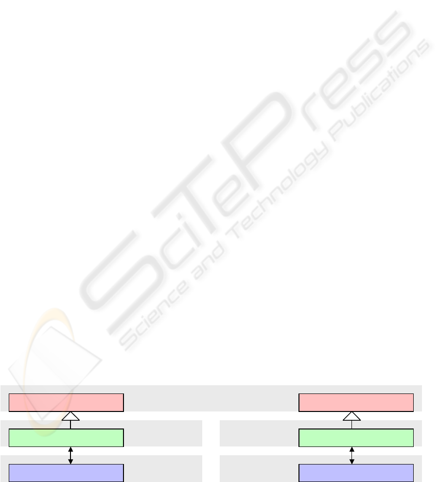
Figure 1: Specialised ArchiMate constructs for UML and Amber (Eertink et al., 1999)
ApplicationComponent
ArchiMate modelling schema
BusinessProcess
UmlApplicationComponent AmberBusinessProcess
Component
UML Amber
Block
UML - ArchiMate
content schema
Amber - ArchiMate
content schema
A TOOL INTEGRATION WORKBENCH FOR ENTERPRISE ARCHITECTURE - Integrating heterogeneous models and
tools
471

To fully integrate a specific modelling language
with the workbench, both a bottom-up and a top-
down transformation are required between that
language and the ArchiMate language. Due to the
potentially different abstraction levels between a
specific language and the ArchiMate language, a
bottom-up transformation is likely to loose details
and a top-down transformation is likely to be
incomplete. In extreme cases a top-down
transformation may only produce a template.
To reduce the abstraction mismatch, ArchiMate
constructs may be specialised by means of ‘isa’-
relations. The workbench may still treat these
constructs as native ArchiMate constructs, while at
the same time the transformations to and from these
constructs can be made more exact. For example, the
ArchiMate construct application component may be
specialised to UML application component in order
to better match the UML construct component
(Figure 1).
2.2 Viewpoint definition
According to IEEE (2000), a viewpoint is a pattern
or template from which to construct individual
views. A viewpoint establishes the purposes and
audience for a view and the techniques or methods
employed in constructing a view.
The ArchiMate workbench adopts an operational
interpretation of IEEE’s viewpoints: A viewpoint
consists of different types of rules, governing the
selection and presentation of view content, and
controlling the interaction with, and interpreting
changes to, the view presentation. Furthermore, a
view might itself be based on another view, leading
to a chain of views instead of a single step from a
model to a view. Ultimately the distinction between
model and view is rather arbitrary.
As the workbench aims to support the
architecture design process, it will focus on so-called
design viewpoints that are dedicated to the design
process. Such viewpoints consist of straightforward
selection, presentation, interaction and interpretation
rules: In the context of the workbench, a design
viewpoint simply defines which modelling
constructs are allowed, with which symbols these
constructs are presented and which connections
these constructs are allowed to have. Nevertheless
the workbench may well serve as a starting point for
more complex viewpoints that are based on more
complex rules and designed to consult models rather
than to manipulate models.
2.3 Transparency and extensibility
To allow easy integration of new modelling tools,
the workbench will adopt a tool adapter pattern, i.e.
an adapter pattern (Gamma et al., 1995) with the
motivation that modelling tools should be made to
integrate by means of ‘plug and play’.
The workbench prescribes the tool adapter
interfaces. The workbench trusts each adapter to be
capable of bottom-up and top-down transformations,
between the adapter’s associated modelling language
and the ArchiMate modelling language.
To obtain transparency, the workbench uses the
tool-specific adapter associated with a modelling
construct to open that modelling construct in its
associated modelling tool.
The ArchiMate workbench also contains a tool
adapter to connect to itself. This may seem trivial,
but is still very useful: Though transformations may
resolve into identity operations, such an adapter will
allow ArchiMate models to be built on top of each
other, realising a chain of views as mentioned in the
previous subsection.
2.4 Architecture
The workbench architecture consists of three tiers: a
workbench tier, an integration tier and a tool tier
(Figure 2). The main component in the workbench
tier is the ArchiMate workbench: The workbench
allows the manipulation of ArchiMate models. Each
ArchiMate model conforms to an ArchiMate
viewpoint that defines which modelling constructs
are allowed, with which symbols these constructs
are presented and which connections these
constructs are allowed to have.
In the tool tier a modelling tool may be used to
Figure 2: The 3-tier workbench architecture
ArchiMate workbench
ArchiMate model ArchiMate viewpoint
Workbench
tier
Integration content Integration schema
Integration
tier
Tool-specific model
Tool
tier
Modelling schema
controls
Tool-specific adapter
Modelling tool
controls
ICEIS 2004 - INFORMATION SYSTEMS ANALYSIS AND SPECIFICATION
472
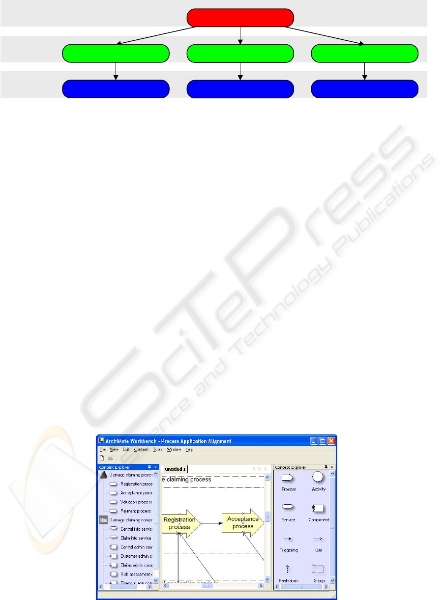
Figure 3: A specific set of modelling tools integrated into the ArchiMate workbench
ArchiMate workbench
Workbench
tier
Integration
tier
Tool
tier
controls
Testbed-specific adapter
Testbed Studio
controls
Custom repository Rational Rose
Custom adapter Rose-specific adapter
controls controls
controls controls
design tool-specific models according to a specific
modelling language.
To allow ArchiMate models to elaborate upon or
break down into tool-specific models, the integration
tier glues modelling tools into the ArchiMate
workbench. The glue used is a tool adapter specific
to each modelling tool: a tool-specific adapter. This
adapter can perform transformations between tool-
specific models and integration content. Along with
integration content, a tool-specific adapter provides
the workbench with an integration schema
describing the underlying modelling language in
terms of possibly specialised ArchiMate constructs.
The ArchiMate workbench controls the tool-
specific adapter: The workbench dictates when to
transform what models or what content and tells
when to open a model in its native modelling tool.
In practice, the workbench architecture typically
integrates a specific set of modelling tools, for
example, Rational Rose, Testbed Studio and a
custom repository (Figure 3).
2.5 Exchange formats
ArchiMate models and integration content are stored
and exchanged using standard XML-based (W3C,
2000) formats. These formats not only prescribe the
way content should be formatted, but also provide a
meta-language to express meta-information about
the content, which helps to interpret that content.
When a tool-specific adapter provides integration
content in XML, it uses this meta-language to
express the integration schema, i.e. what modelling
constructs that content uses. For example, a Rose-
specific adapter (Figure 3) would use the meta-
language to specify a schema with a UML-specific
version of the ArchiMate concept Application
Component.
Examples of XML-based exchange formats that
come with meta-languages are XML itself, XMI
(OMG, 2003a) and OIFML (ODMG, 2000).
Corresponding meta-languages are XML Schema
(W3C, 2001), XML Schema and ODL (ODMG,
2000) respectively. At this point we opt for XMI,
because it is alive and has already been widely
adopted for the exchange of models.
3 WORKBENCH AT WORK
Before the requirements of the workbench dynamics
are illustrated with some scenarios, a short
introduction into the workbench GUI is presented.
The workbench GUI divides the application window
Figure 4: Workbench user interface
A TOOL INTEGRATION WORKBENCH FOR ENTERPRISE ARCHITECTURE - Integrating heterogeneous models and
tools
473
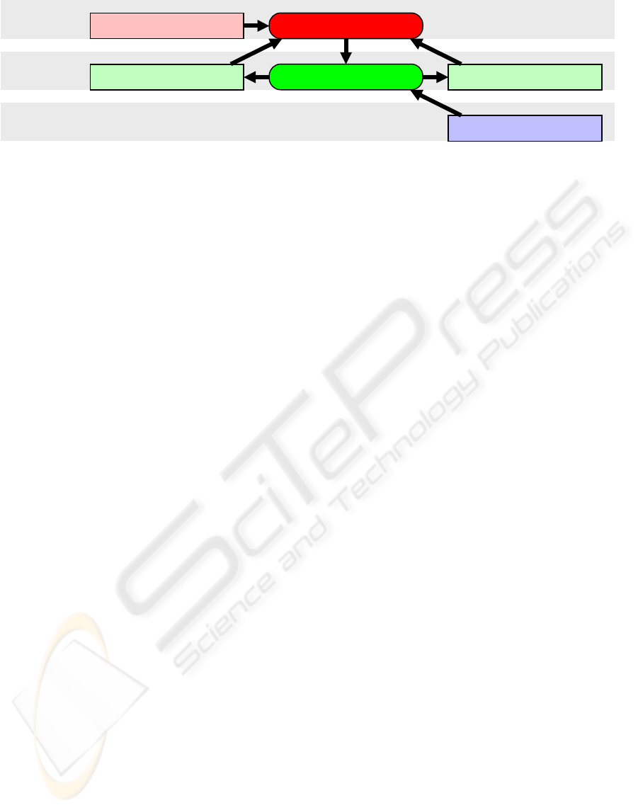
Figure 5: Bottom-up design
ArchiMate workbench
ArchiMate viewpoint
Workbench
tier
Integration content Integration schema
Integration
tier
Tool-specific model
Tool
tier
Tool-specific adapter
1
1
1
2 2
2
1
in 3 frames (Figure 4): A content explorer, a canvas
for modelling and a concept explorer.
The concept explorer shows the ArchiMate
modelling constructs, or actually their symbols,
specified by a certain viewpoint, e.g. a viewpoint
focusing the relation between software components
and business processes.
The content explorer shows hierarchical
representations of the tool-specific models upon
which the currently open ArchiMate model is based.
These tool-specific models have been translated into
(possibly specialised) ArchiMate constructs. Only
constructs relevant to the viewpoint are shown in the
content explorer. Examples of ArchiMate constructs
relevant to the relation between business processes
and software components are: business process,
application service, application interface,
application component, use and realisation.
The canvas shows the currently opened
ArchiMate model. Objects may be added to the
model in 2 ways: 1. Objects from the content
explorer may be dragged and dropped onto the
canvas. These objects are in fact references to
objects in the underlying tool-specific models. 2.
Constructs from the concept explorer may be
dragged and dropped onto the canvas. This way,
newly created instances of those constructs are
added to the model.
The GUI serves as a starting point for 4
scenarios, each focusing different aspects of the
workbench at work:
– Getting started – Start an ArchiMate model
from an ArchiMate viewpoint.
– Bottom-up design – Embed content from a tool-
specific model in an ArchiMate model.
– Tool start-up – Open an object associated with a
tool-specific model in its native modelling tool.
– Top-down design – Specialise an object in a
newly created tool-specific model.
3.1 Getting started
According to the IEEE 1471 conceptual model,
viewpoints are used to cover concerns that
stakeholders have. Therefore, the workbench
provides the user with a wizard to determine what
type of stakeholder the user is and what concerns the
user has. The wizard uses this information to lead
the user to a set of possible viewpoints in which he
or she might be interested. Choosing a viewpoint
opens a new ArchiMate model having an empty
content explorer, an empty canvas and a concept
explorer containing symbols representing the
constructs specified by the viewpoint. The user may
now drag and drop constructs from the concept
explorer onto the canvas. Subsequently, the user
may relate objects wherever the viewpoint allows
relations.
3.2 Bottom-up design
ArchiMate models may elaborate upon and integrate
existing tool-specific models allowing models to be
designed in a bottom-up fashion. To embed existing
content into an ArchiMate model, the user selects a
model for which a tool-specific adapter has been
registered with the workbench. Choosing a model
creates a tree-representation of that model in the
content explorer. To achieve this, the workbench
performs the following steps (Figure 5):
The workbench uses the adapter to translate the
tool-specific model into integration content. Along
with the integration content, the adapter provides the
workbench with an integration schema.
The workbench uses the integration schema to
retrieve constructs from the content. Subsequently,
the workbench uses the ArchiMate viewpoint that
was used to create the ArchiMate model, to select
only those constructs that are part of the viewpoint
and to find symbols for them.
The user may now drag and drop objects from
the content explorer onto the canvas.
3.3 Tool start-up
Once the user has used objects from the content
explorer, or more precisely, has created references to
objects in the underlying tool-specific models, the
user may open the referred objects in their native
modelling tool: The workbench allows the user to
ICEIS 2004 - INFORMATION SYSTEMS ANALYSIS AND SPECIFICATION
474

Modelling tool
Figure 6: Tool start-up
ArchiMate workbench
Workbench
tier
Integration
tier
Tool-specific model
Tool
tier
Tool-specific adapter
select an object in the model. If the selected object is
associated with a tool-specific adapter, or in other
words, if the object has a tool-specific counterpart,
the workbench allows the user to open the model
containing the tool-specific counterpart in its native
modelling tool.
Because the workbench wants to abstract from
tool-specific knowledge, the workbench does not
start-up associated tools itself, but uses the
associated adapters to do that instead (Figure 6).
3.4 Top-down design
The user may not only extend existing models, but
may break down abstract ArchiMate models into
more specific models as well. Thus, the workbench
allows a top-down design approach.
Again, the workbench allows the user to select a
set of objects in the canvas. If the objects are not
already associated with a tool-specific adapter, i.e.,
if the objects do not have a tool-specific counterpart,
the workbench allows the user to specialise the
selected objects. Choosing this option triggers the
first step in the top-down design process (Figure 7):
1. For each registered tool-specific adapter, the
workbench retrieves the tool-specific integration
schema and checks the availability of the
constructs to be specialised. This way, the
workbench produces a list of modelling tools that
support the constructs at issue.
The workbench presents the list of modelling
tools to the user. The user chooses a modelling tool
after which the workbench continues as follows:
2. The workbench passes the object, or actually the
integration content to be specialised, to the
adapter associated with the elected modelling
tool.
3. The adapter generates a tool-specific model and
translates the integration content into this model.
4. Finally, the workbench transforms the object in
the ArchiMate model into an object that is a
reference to the newly created tool-specific
content.
The user may now open the referred objects in
their native modelling tool.
3.5 Example
To illustrate the value of the workbench an example
is presented: An existing UML model and an
existing Amber model (Eertink et al., 1999) are
integrated in an ArchiMate model (Figure 8).
The UML model depicts a number of application
components that are used by the imaginative
insurance company ArchiSurance. The components
are translated to ArchiMate components in a
straightforward way. The Amber model represents a
number of process blocks that realise claim handling
from registration to payment. This model is
translated to ArchiMate concepts as well. Now, the
workbench can be used to order the objects and
define relations between them. In this case a layered
architecture is created with services that are realised
by components and provided to business processes.
This results in a view relating business processes to
IT components by means of service concepts. The
following operations are applied in the creation of
the integrated model:
Figure 7: Top-down design
ArchiMate workbench
ArchiMate model
Workbench
tier
Integration content Integration schema
Integration
tier
Tool-specific model
Tool
tier
Tool-specific adapter
1
1
1 2
3
2
4
A TOOL INTEGRATION WORKBENCH FOR ENTERPRISE ARCHITECTURE - Integrating heterogeneous models and
tools
475

Valuation
Acceptance
Registration
Registration Acceptance Valuation
Payment
Claims
administration
service
Customer
administration
service
Risk
assessment
service
Payment
service
Claims
administration
Customer
adminstration
Risk
assessment
Financial
application
Claim
information
service
Damage claiming process
External application services
Application components and internal services
Payment
Claims
administration
Customer
administration
Risk
assessment
Financial
application
Formal
claim
Policy
(contract)
Central
administration
Figure 8: An ArchiMate model (right) based on an Amber model (top left) and a UML model (bottom left)
– Translation: The interface offered by the Claims
administration component is translated to the
Claim information service. UML dependency
relations are translated to ArchiMate use
relations.
– Selection: Mainly processes and components are
selected. Most interfaces, data items, business
activities are left out. The Central administration
component is left out.
– Extension: services offered by components to
processes are added; concepts are grouped using
ArchiMate grouping constructs.
4 RELATED WORK
This section gives a short overview of the literature
on tool integration. It presents an overview of tool
coordination frameworks and model integration
approaches without going into details of general
low-level mechanisms like middleware,
broadcasting and message passing.
4.1 Tool coordination frameworks
In tool coordination frameworks each tool is
wrapped with a piece of software that exposes the
characteristics of the tool in a standardised way to its
environment. The environment consists of other
(wrapped) tools and a management component that
coordinates the communication and coordination
between the tools. The degree to which the tool’s
functionality is published by a wrapper may differ.
METAFRAME (Claßen et al., 1997) is an advanced
tool integration framework that allows integration of
data, control and presentation. Furthermore, it offers
a coordination language for programming the
coordinated behaviour of integrated tools. ToolBus
(Bergstra and Klint, 1998) is another example of
coordination: It is a programmable software bus that
coordinates the cooperation of a number of tools by
running scripts. Another characteristic of ToolBus is
the strict separation between coordination (done by
the ToolBus), computation (control) and
representation (presentation). Wrappers are used to
decouple computation from representation and wrap
them in order to disclose them to the ToolBus. The
Manifold language described by Arbab et al. (1993)
is a parallel programming language that can be
applied to manage the coordination between tools.
The UniForm Workbench (Karlsen, 1998) is
based on existing standards of which the Portable
Common Tool Environment (PCTE) specification of
ECMA (ECMA, 1997) had the most influence on the
architecture. The environment is an open-ended tool
integration framework for developing (formal)
software development environments from the basis
of Commercial-of-the-Shelf (COTS) development
tools. The integration framework provides support
for data, control and presentation integration as well
as utilities for wrapping Haskell interfaces around
existing development tools. Entire software
development environments are then glued together
on the basis of these encapsulations using
Concurrent Haskell as the integration language.
Nuseibeh and Finkelstein (1992) propose to use
viewpoints as the basic concept for method and tool
integration. A development method is defined as a
collection of viewpoints each of which is supported
by a tool. An implementation is described that
manages and integrates viewpoint as SmallTalk
objects. In (Kramer and Finkelstein, 1991)
viewpoints are treated as configuration items in an
approach based on software configuration.
4.2 Model integration
In model integration heterogeneous models
expressed in domain-specific modelling languages
ICEIS 2004 - INFORMATION SYSTEMS ANALYSIS AND SPECIFICATION
476

are related and/or integrated. In general two
approaches exist here:
– Direct model integration: Direct relations
between concepts in heterogeneous languages
are established. An ontology may be used to
define what concepts semantically are the same,
and which relations may exist between concepts.
A drawback of direct model integration is that
each language that must be added requires O(n)
relations to the n other languages.
– Integrated metamodels: Based on the
metamodels of heterogeneous languages an
integrated metamodel is created synthesised with
mappings to and from the domain-specific
languages. Creasy and Ellis (1993) proposed to
use conceptual graphs of Sowa as language for
the specification of the integrated metamodels.
This is similar to the ArchiMate approach
(Jonkers et al., 2003) in which a rich metamodel
is developed for enterprise architecture models
with mappings to/from domain-specific
modelling languages like UML (OMG, 2003b)
and BPML (BPMI, 2003).
Grundy and Venable (1995) present an
integration environment in which different
modelling languages have their own repository and
editor while changes in one model are propagated
through a central repository based on an integrated
data model to the other models.
Karsai (2000) describes an integration
framework based on model integration. The
architecture proposed is based on tool wrappers that
translate tool-specific models to a syntactic
modelling language resembling ER, after which a
semantic interpreter interprets these models and
stores them in a central repository. The framework
assumes that the presentation layer of tools is left
untouched.
The WOTIF (WOTIF) project aims at
developing an open framework for integrating
design tools for embedded system development.
Design flows today are realized using different,
proprietary design tools, whose integration is a
complex problem. WOTIF provides a meta-model
driven infrastructure for design tool integration,
which facilitates the semantic interoperability across
the elements of a tool chain. WOTIF is implemented
on the basis of Eclipse, an open extensible Integrated
Development Environment (IDE).
5 CONCLUSION
In this paper we have presented the design of a tool
integration workbench that is able to integrate
existing modelling tools. It shows that it is possible
to practice enterprise architecture while at the same
time keeping existing modelling artefacts.
Leaving existing modelling environments intact,
the workbench allows the concurrent design of
enterprise architecture domains: each domain may
still be designed using its own languages, tools and
techniques. More importantly, with the ability to
reason across domain boundaries the workbench
introduces an instrument for collaborative design.
By adopting the ArchiMate modelling language,
the workbench not only allows the integration of
existing modelling languages, but provides a
language to communicate across domain boundaries
as well. Moreover, the workbench serves as a
starting point for the analysis of enterprise
architectures using generic analysis techniques that
rely on the ArchiMate modelling language.
An important success factor left unaddressed in
this work is the mechanism responsible for the
synchronisation of models that share objects. This
subject requires further investigation.
Another key factor in the success of the
workbench architecture is the feasibility of
transformations between tool-specific content and
ArchiMate content. The semantic soundness of such
transformations is particularly nontrivial and thus
requires further exploration.
One of the goals of the ArchiMate project is to
stimulate innovation in the market of tools for the
enterprise architecture design process. The ideas
presented should challenge vendors of such tools to
(1) provide interoperability services, e.g. tool-
specific adapters, such that their tool can be
integrated in environments like the one presented
here, (2) create commercial versions of tool
integration environments and (3) create graphical
modelling tools that allow relating and integrating
existing models.
In the near future, ArchiMate will create
prototype versions of the environment in order to
show that the workbench approach is feasible and
can be turned into commercial products. Attention
will be paid to transformations, synchronisation of
models that share objects, and the analysis of
enterprise architectures. Furthermore, the workbench
will be validated in pilot projects running at the
companies involved in ArchiMate.
ACKNOWLEDGEMENT
This paper results from the ArchiMate project
(
http://archimate.telin.nl/), a research initiative that
aims to provide concepts and techniques to support
enterprise architects in the visualisation,
communication and analysis of integrated
A TOOL INTEGRATION WORKBENCH FOR ENTERPRISE ARCHITECTURE - Integrating heterogeneous models and
tools
477

architectures. The ArchiMate consortium consists of
ABN AMRO, Stichting Pensioenfonds ABP, the
Dutch Tax and Customs Administration, Ordina,
Telematica Instituut, Centrum voor Wiskunde en
Informatica, Katholieke Universiteit Nijmegen, and
the Leiden Institute of Advanced Computer Science.
Special thanks go to Andries Stam of Ordina,
who offered his profound reviewing skills.
REFERENCES
Arbab, F., I. Herman and P. Spilling, 1993. An overview
of Manifold and its implementation.
Concurrency:
Practice and Experience
5(1), pp. 23-70.
Bergstra, J.A. and P. Klint, 1998. The discrete time
ToolBus -- a software coordination architecture.
Science of Computer Programming 31(2-3), pp. 205-
229.
Bernus, P., Nemes, L., Schmidt, G., 2003.
Handbook on
Enterprise Architecture
, Springer.
BPMI, 2003.
Business Process Modeling Language
(BPML), Proposed Recommendation
. Business
process Management Initiative (BPMI). URL:
http://www.bpmi.org.
Claßen, A., Steffen, B., Margaria, T., and Braun, V., 1997.
Tool Coordination in METAFrame.
Technical Report
MIP9707
. Universität Passau, Germany.
Creasy, P. N. and Ellis, G., 1993. A Conceptual Graph
Approach to Conceptual Schema Integration. In Proc.
ICCS’93, Conceptual Graphs for Knowledge
Representation: First International Conference on
Conceptual Structures
. Quebec, Canada.
ECMA, 1997. Portable Common Tool Environment
(PCTE) – Abstract Specification.
Standard ECMA-
149
. ECMA Standardizing Information and
Communication Systems. URL:
http://www.ecma-
international.org/.
Eertink, H., Janssen, W., Oude Luttighuis, P., Teeuw, W.
and Vissers, C., 1999. A Business Process Design
Language. In Proc.
1st World Congress on Formal
Methods
. Toulouse, France.
Gamma, E., Helm, R., Johnson, R. and Vlissides, J., 1995.
Design Patterns: Elements of Reusable Object-
Oriented Software
. Reading Mass., Addison Wesley.
USA, 1
st
edition.
Grundy, J.C. and Venable, J.R., 1995. Providing
Integrated Support for Multiple Development
Notations. In Proc.
Conference on Advanced
Information Systems Engineering
, pp. 255-268.
Handler, R., 2003.
Selecting Architecture Modeling Tools:
2003. EPAS, META Group.
Iacob, M.
et al., 2002. State of the Art in Architecture
Support
. ArchiMate deliverable D3.1. Telematica
Instituut, Enschede, The Netherlands. URL:
https://doc.telin.nl/dscgi/ds.py/Get/File-27882/.
IEEE, Architecture Working Group, 2000.
IEEE Std 1471-
2000, IEEE Recommended Practice for Architectural
Description of Software-Intensive Systems
. IEEE.
USA.
Jonkers, H.
et al., 2003. Towards a language for coherent
enterprise architecture descriptions. In
EDOC’03, 7th
IEEE International Enterprise Distributed Object
Computing Conference
, pp. 28-37. Australia.
Karlsen, E.W., 1998. The UniForM WorkBench – a
Higher Order Tool Integration Framework.
International Workshop on Current Trends in Applied
Formal Methods (AFM’98)
. Boppard, Germany.
Karsai G., 2000. Design Tool Integration: An Exercise in
Semantic Interoperability.
Proceedings of the IEEE
Engineering of Computer Based Systems
. Edinburg,
UK.
Kramer, J. and Finkelstein, A., 1991. A Configurable
Framework for Method and Tool Integration. In
Software Development Environments and CASE
Technology
, pp. 233-257.
Nuseibeh, B. and Finkelstein, A., 1992. View Points: A
Vehicle for Method and Tool Integration.
Proceedings
of the Fifth International Workshop on Computer-
Aided Software Engineering
. IEEE Computer,
Montreal, Canada.
ODMG, 2000.
Using XML as an Object Interchange
Format
. Object Data Management Group. URL:
http://www.odmg.org/.
OMG, 2003a.
XML Metadata Interchange (XMI), v2.0.
Object Management Group. URL:
http://www.omg.org/cgi-bin/doc?formal/03-05-02.
OMG, 2003b.
Unified Modelling Language, v1.5, Object
Management Group. URL:
http://www.omg.org/cgi-
bin/doc?formal/03-03-01.
Schefstroem, D. and van den Broek, G., 1993.
Tool
Integration: Environments and Frameworks
. John
Wiley & Sons, New York.
W3C 2000.
XML 1.0. World Wide Web Consortium.
URL:
http://www.w3.org/XML/.
W3C 2001.
XML Schema 1.0, World Wide Web
Consortium. URL:
http://www.w3.org/XML/Schema.
WOTIF.
Web-based Open Tool Integration Framework.
Institute for Software Integrated Systems. URL:
http://www.isis.vanderbilt.edu/Projects/WOTIF.
ICEIS 2004 - INFORMATION SYSTEMS ANALYSIS AND SPECIFICATION
478
