
A PROTOTYPE TOOL FOR USE CASE REFACTORING
Shengbing Ren
Central South University
Changsha, Hunan, 410083 P.R.China
Greg Butler, Kexing Rui, Jian Xu, Wei Yu, Renhang Luo
Concordia University
Montr
`
eal H3G 1M8,Canada
Keywords:
reuse, software evolution, use case, refactoring tool
Abstract:
Use cases are widely used in software engineering. It is important to improve the understandability and
maintainability of use case models. We propose the approach of refactoring use case models. This paper
describes a prototype tool for the refactoring process. We introduce the use case metamodel and its XML
document type definition (DTD) used in the tool. Based on the Drawlets framework, we implement the
functionality for drawing and viewing use case models. We propose the refactoring framework and implement
some use case refactorings. Our experience shows that the tool greatly facilitates the process to reorganize use
case models.
1 INTRODUCTION
Use cases and scenarios play an important role in
object-oriented software engineering. A use case rep-
resents a series of transactions between the actor and
the system. An actor represents a certain user type
or a role played by users. A scenario is a specific
and bound realization of a use case. Use cases and
scenarios not only elicit requirements from stakehold-
ers to construct object-oriented software systems, but
also are essential for understanding existing object-
oriented software systems. Furthermore, many soft-
ware artifacts, such as state chart, test cases, can be
derived from them (Uchitel, 2003) (Ryser, 2000).
It is a challenge to manage use case models effec-
tively during software evolution. In our research we
extend the concept of refactoring from source code
to use case models. Our work attempts to show how
refactoring as a concept can be broadened to apply
to use case models to improve their understandability,
changeability, reusability and traceability. This pa-
per describes a prototype tool for refactoring use case
models. It is organized as follows. In section 2, we in-
troduce some related work in refactoring. We present
our use case metamodel in section 3 and describe the
design and implementation of the tool in section 4.
We summarize this paper and discuss the future work
in section 5.
2 RELATED WORK
2.1 PROGRAM REFACTORING
Refactoring is a program transformation approach
for iterative software development. W. F. Opdyke
(Opdyke, 1992) coins the term refactoring to stand for
the program restructuring operation that preserves the
program behavior for object-oriented applications. In
(Fowler, 2002), M. Fowler describes refactoring prin-
ciples and its uses. A comprehensive list of refactor-
ings are described with motivation, mechanics, and
examples. D. Roberts presents a weaker and more
practical definition for refactoring in (Roberts, 1999).
There are many tools available for source code
refactoring. The Refactoring Browser is the first
commercial-grade refactoring tool (Roberts, 1997)
(Roberts, 1999) for Smalltalk. It implements most of
the standard class, method and variable refactorings.
It has become an essential tool for the Smalltalk pro-
grammer. JFactor (Instantiations) is the most com-
plete refactoring tool for Java. It is a plug-in for
IBM Visual Age. There are three kinds of refactor-
ings: field refactorings, method refactorings and class
refactorings. Transmogrify (McCormick) is a frame-
work to parse and modify Java programs. It has im-
plemented several refactorings, such as rename vari-
able or method, extract method, replace temp with
query, inline temp, and pull up field.
173
Ren S., Butler G., Rui K., Xu J., Yu W. and Luo R. (2004).
A PROTOTYPE TOOL FOR USE CASE REFACTORING.
In Proceedings of the Sixth International Conference on Enterprise Information Systems, pages 173-178
DOI: 10.5220/0002615401730178
Copyright
c
SciTePress
2.2 USE CASE MODEL
REFACTORING
As a concept, refactoring can be used not only for pro-
gram transformation, but also for the whole software
life cycle. G. Sunye et al (Gogolla, 2001) define some
refactorings to restructure the class diagram and state
chart. S. Stepney et al (Stepney, 2002) show that
refactoring concepts can be applied to Z specification
upgrades. J. Philipps et al believe that the core con-
cept of refactoring can be applied for a large num-
ber of modeling techniques beyond mere program-
ming languages, and list a set of refactorings to trans-
form system structure model and state machine model
(Philipps, 2001). In (Butler, 2001), G. Butler et al ex-
tend the concept of refactoring to the whole range of
models used to describe a framework: feature model,
use case model, architecture, design, and code. Cas-
caded refactoring relates the set of refactorings across
the set of models through change impact analysis with
the trace maps.
A use case refactoring preserves the set of the di-
alogues of the target system (Butler, 2001). A use
case is a description of a cohesive set of dialogues that
the primary actor initiates with a system. Those dia-
logues are related to the same task, or form part of the
same transaction. They define the functionality of the
system. Hence, they are the only appropriate things
to preserve upon restructuring. The use case model
is factored by introducing abstract use cases, and re-
arranging responsibilities. This allows the use case
model to reflect the commonality/variability analysis.
Through refactoring, the quality of use cases and sce-
narios, such as reusability, conciseness, maintainabil-
ity, and readability, is improved. The following ex-
ample will show how to improve the quality of the
use case model.
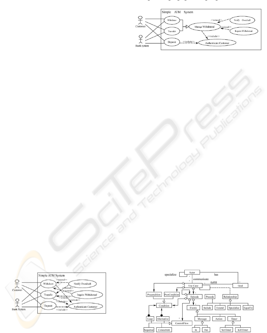
There is a simple ATM system. Figure 1 shows the
use case model. Through the following steps, the use
case model becomes more reusable, concise, main-
tainable, and readable. Figure 2 shows the result.
Figure 1: Simple ATM System Use Case Model.
a)Create an empty use case ”Manage Withdrawal”.
b)Make ”Manage Withdrawal” a super use case of
”Withdraw” and ”Transfer” using inherit refactoring.
c)Move the common description between ”With-
draw” and ”Transfer” to ”Manage Withdrawal” using
push episode up to general use case refactoring.
Figure 2: Refactored Simple ATM System Use Case Model.
Just like source code refactoring, the automatic tool
support for use case model refactoring is very impor-
tant to efficiently refactor use case model. During
the refactoring, many conditions should be checked,
such as push refactoring. Some times, the refactor-
ings which are done previously should be cancelled
for some reasons. For the manual refactoring, these
things may be very complicated. Our work is to try
to construct a use case refactoring tool to support use
case modeling.
3 USE CASE METAMODEL
There is a strong debate about the semantics of use
cases. Different methods interpret the semantics of
use case related concepts differently (Regnell, 1999).
In (Cockburn, 1997), A. Cockburn identified 18 dif-
ferent definitions of use cases that he encountered.
Although UML represents some efforts in use case
formalization, there is still a lot of debate on this is-
sue.
In order to implement use case refactorings, we
have to define use case semantics clearly. We do not
intend to define a formal use case semantics. Our fo-
cus is to provide good support for requirements engi-
neering. The metamodel should be suitable for auto-
matic refactoring, checking and synthesizing. Figure
3 shows our use case metamodel.
Figure 3: Use Case Metamodel.
There are four major components in our use case
metamodel: actor, use case, episode, and event. An
ICEIS 2004 - INFORMATION SYSTEMS ANALYSIS AND SPECIFICATION
174
actor, which represents a category of external users,
communicates with the system, i.e. use cases, to ful-
fill its goals. Goals represent functionality required of
the system, which can be used to categorize users into
actors. Between two actors, there is only one rela-
tionship: specialization. Each use case has a precon-
dition and postcondition, which demarcates the scope
of the use case. A use case is a description of a cohe-
sive set of dialogues that actor communicates with the
system. There are five kinds of relationships between
two use cases, and two kinds of relationships are dif-
ferent from the UML (OMG, 2002). The Precede re-
lationship defines that one use case is sequenced (ap-
pended) to the behavior of the preceding use case. It
is very useful in some application. The EqualTo re-
lationship defines that one use case’s behavior is the
same as the other use case. It can be very useful for
requirement eliciting. Episode can be used to struc-
ture use case. It represents a coherent part of the use
case. Episode can be referenced by different use cases
or other episodes. The control flow is added to de-
scribe more complex dialogues. Condition is used to
describe the status of actor or the property of the en-
vironment and the target system that needs to be ful-
filled in order to invoke dialogues. There are three
kinds of events: message, action, and timer. The ”In”
message and ”Out” message always appear as a pair.
The ”Out” message is earlier than the correspondent
”In” message. The action event is an internal event of
actor. The timer events: SetTimer and KillTimer, are
used to describe time constraints.
Our use case metamodel incorporates B. Regnell’s
work (Regnell, 1999) as well as other people’s work
in use case modeling. There are three different lev-
els of abstraction. At the use case level, use case
is related to the external entities, i.e. actors. At the
episode level, the internal episode structure of the use
case is described together with its different variants
and parts by defining sequences, alternatives, loops,
and concurrencies. At the event level, episode is de-
scribed in further detail in term of events that occurred
in each episode.
4 TOOL DESIGN AND
IMPLEMENTATION
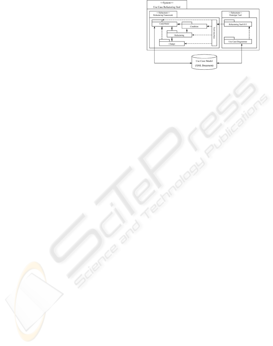
4.1 OVERVIEW
In our use case refactoring tool, there are two subsys-
tems (see Figure 4): the refactoring framework and
the prototype tool. The refactoring framework is inde-
pendent to the prototype tool. Two subsystems com-
municate through the Facade design pattern (Gamma,
1994).
Figure 4: Overview Of Use Case Refactoring Tool.
In the refactoring framework, the Refactoring pack-
age conducts the whole refactoring process. Each
refactoring has a precondition, which is an object of
the Condition package. At the beginning of the refac-
toring, the precondition is checked. During the check-
ing process, the condition object communicates with
the code model object. The code model object an-
alyzes the use case model, and determines whether
the precondition is met or not. If the precondition is
met, the refactoring object generates a change object
to modify the use case model. The change object will
communicate with the code model object to complete
the corresponding change, and return a change object
which is used to undo the change. The Tool Interface
package is utilized to communicate with the proto-
type tool subsystem. We will describe these packages
in detail in following sections.
We also use the prototype tool to evaluate the
refactoring framework. It contains two packages: a
Refactoring Tool GUI and a Use Case Diagrammer.
Through the Refactoring Tool GUI, user can initi-
ate a refactoring and input corresponding information.
Then Refactoring Tool GUI will send the requirement
to the refactoring framework Tool Interface package
to complete the refactoring. After refactoring, user
can view the result through the Use Case Diagram-
mer.
4.2 STORAGE
XML is widely accepted for storage and information
exchange (Yamane, 2000). It provides a number of
positive attributes, such as tractability, extensibility,
structure, openness, and independence between data
and style. Document Type Definition (DTD) provide
a grammar for creating XML document structure. We
store use case model using the XML format. Figure
5 shows the DTD that is used to structure the storage
of our use case model.
In our DTD, there are four major entities: Actor,
Usecase, Episode, and Extend. An Actor entity con-
tains the actor information, such as name, communi-
A PROTOTYPE TOOL FOR USE CASE REFACTORING
175
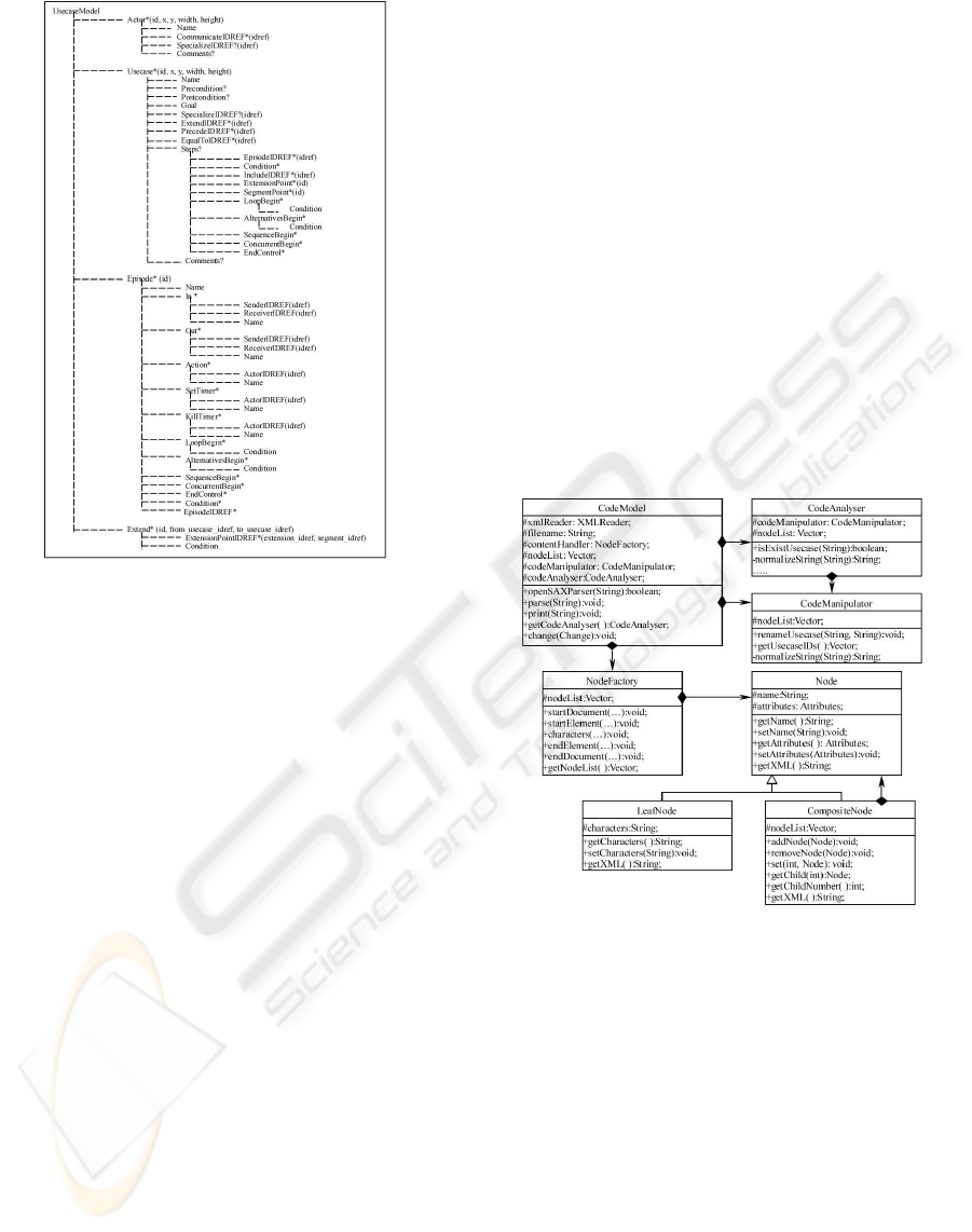
Figure 5: The Structure Of The Use Case Model DTD.
cating use case, parent actor, and so on. The id at-
tribute of an Actor entity identifies the actor. Other
attributes: x, y, width and height, are used by the
use case diagrammer to store the position and size of
the actor figure. A Usecase entity stores the use case
information. Each Usecase entity has an identifica-
tion attribute id. Other attributes are used by the use
case diagrammer, just like those of the Actor entity.
The relationships between two use cases are stored
respectively by SpecialIDREF, ExtendIDREF, Pre-
cedeIDREF, EqualToIDREF and IncludeIDREF. The
idref attribute in the relationship entity refers to the
id value of the corresponding use case. An EpisodeI-
DREF entity stores the information of the referenced
episode. An Episode entity keeps the episode infor-
mation, such as message event, action event and timer
event with some control flow elements and condi-
tions. Extend entity stores the extend relationship in-
formation, such as the extension point, segment point
and the extension condition. Other entities are self ex-
planatory. Owing to the paper size, we do not discuss
them here.
4.3 REFACTORING
FRAMEWORK DESIGN
There are five packages in the refactoring framework:
Code Model, Refactoring, Condition, Change, and
Tool Interface. The Code Model represents the use
case model within the framework. The Refactoring
package is one of the core components. Each refac-
toring class represents a refactoring itself. The Condi-
tion package is used to describe the precondition and
postcondition of refactoring. It is very easy to test
equality between any two conditions using condition
class. Modifications which the refactoring makes to
the code model are represented using change classes
within Change packages. The Tool Interface pack-
age provides various methods to communicate with
the previous four packages that act as a facade.
The Code Model package provides two categories
of classes. One includes the NodeFactory class, Node
class, LeafNode class, and CompositeNode class. It
is used to parse the XML document which stores the
information of the use case model. The other includes
the CodeModel class, CodeAnalyser class, and Code-
Manipulator class. It is used to process the use case
model to complete a refactoring operation. Figure 6
shows the class diagram of the Code Model package.
Figure 6: The Code Model Package.
There are two kinds of refactorings in the Refac-
toring package: primitive refactorings and composite
refactorings. It is convenient to describe a refactoring
using the Composite pattern (Gamma, 1994), with
one subclass for each primitive refactoring and an-
other for composite refactorings. Figure 7 shows the
class diagram of the Refactoring package.
The condition classes within the Condition package
are organized by the Composite pattern as shown in
Figure 8. The name of the condition class is the name
of the analysis function within the precondition and
postcondition of the refactorings. For example, isUse-
caseCondition represents isUsecase analysis function.
There are no explicit pre- and post-conditions in
composite refactorings. They can be calculated ac-
cording to the algorithms proposed by D.B.Roberts
ICEIS 2004 - INFORMATION SYSTEMS ANALYSIS AND SPECIFICATION
176
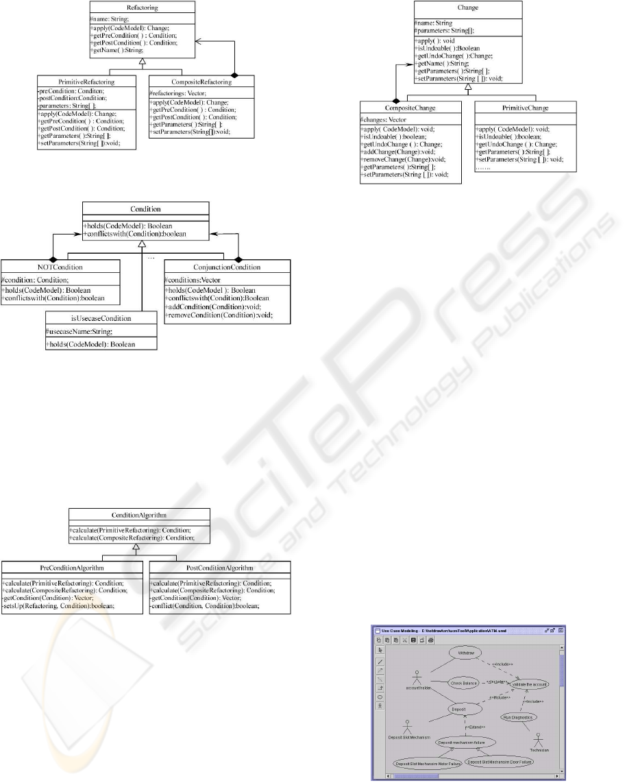
Figure 7: The Refactoring Package.
Figure 8: The Condition Package.
(Roberts, 1999) and M.O.Cinneide (Cinneide, 2000)
from the stored primitive refactorings. The Condi-
tionAlgorithm class is used to calculate the pre- and
post-conditions of the composite refactoring. Figure
9 shows the class diagram.
Figure 9: The ConditionAlgorithm Class.
The change classes within the Change package are
organized using the Composite pattern to allow multi-
ple changes to be represented. Each refactoring is re-
lated to a change class. The getUndoChange method
returns another change object to undo the change.
Figure 10 shows the class diagram.
The tool interface is a facade class. There are var-
ious methods which are related to the refactorings in
tool interface class, such as renameUsecase, extract-
IncludedUsecase, getUsecases, parse, print and so on.
It delegates the tool GUI requests to appropriate sub-
system classes. In so doing, it minimizes the commu-
nication and dependencies between subsystems.
Figure 10: The Change Package.
4.4 TOOL IMPLEMENTATION
At present, there are two packages within the proto-
type tool: a Refactoring Tool GUI and a Use Case Di-
agrammer. The Refactoring Tool GUI interacts with
the tool interface class within the refactoring frame-
work to complete the refactoring requirements. The
Use Case Diagrammer is used to draw the use case
model. Refactoring results can be viewed through the
Use Case Diagrammer.
In our project, the Use Case Diagrammer is im-
plemented based on the Drawlets framework (Role-
Model Software). Several classes, such as Simple-
DrawingCanvas, SimpleDrawing and BasicObserv-
able, are modified. We add some new shapes such
as actor, use case, and so on, based on the original
shapes. Furthermore, we implement the attribute pane
for some shapes, such as actor and use case, to de-
fine attributes of shapes. In order to store the use
case model in the XML format, some classes are also
added to the framework to parse and print the use
case model. Figure 11 shows the screen shot of use
case diagrammer which is implemented based on the
Drawlets framework.
Figure 11: A Screen Shot Of Use Case Diagrammer.
The Refactoring Tool GUI provides various refac-
toring panes. Figure 12 shows a screen shot of the
A PROTOTYPE TOOL FOR USE CASE REFACTORING
177
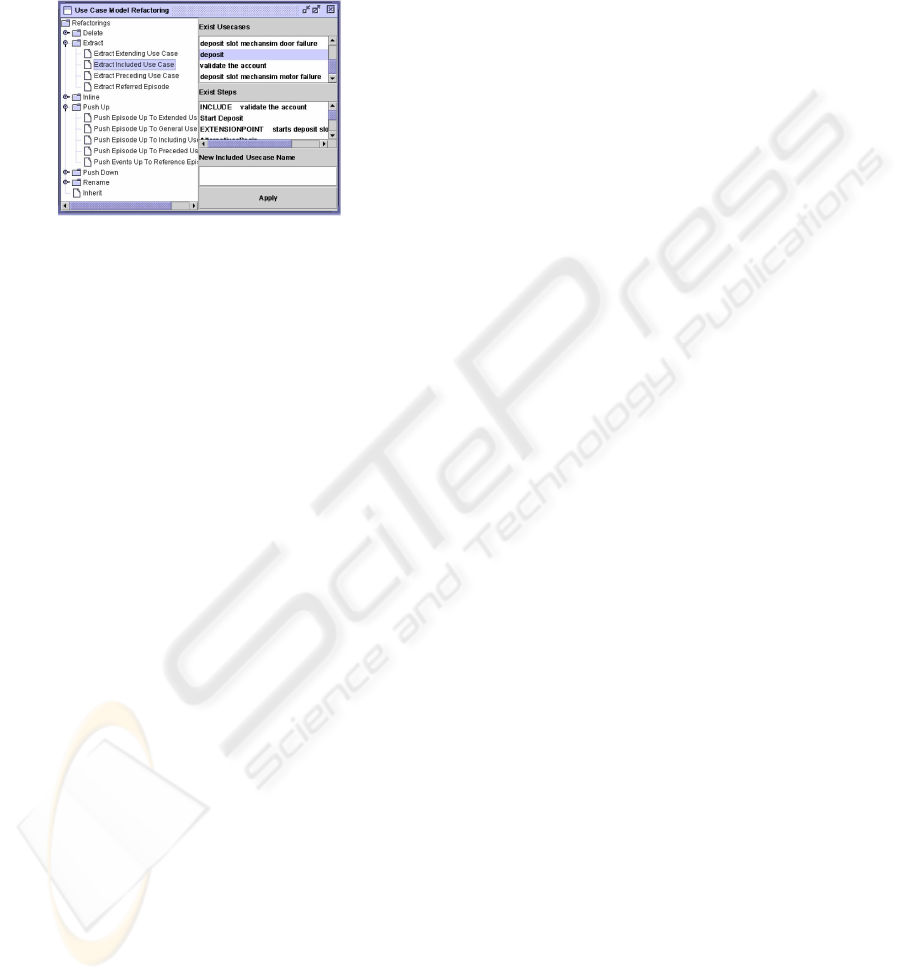
Refactoring Tool GUI. At the left side, a list of refac-
torings are displayed through a tree structure. When
user selects a refactoring, a corresponding input pane
is displayed at the right side. The developer can input
the required input and then click the Apply button to
start the refactoring.
Figure 12: A Screen Shot Of Refactoring Tool GUI.
5 CONCLUSION
This paper introduces our practice in designing and
implementing a tool for refactoring use case mod-
els. We present our refactoring framework, which is
tool independent and flexible owing to the utilization
of software design patterns. Currently, twenty-four
refactorings have been implemented, such as rename
refactorings, extract refactorings, inline refactorings,
push up refactorings, push down refactorings, and so
on. With the tool support, we can conduct use case
refactorings easily and effectively. Based on our ex-
perience, the tool has achieved its initial success. As
the next step, we will implement more use case refac-
torings into the tool. We will also conduct several
case studies to evaluate the tool as well as our use case
refactorings. Our refactoring framework is also sub-
ject to further evaluation. We will investigate compos-
ite refactorings and use case pattern (Adolph, 2002)
functionality.
REFERENCES
S. Uchitel, J. Kramer, and J. Magee. (2003). Synthesis of
Behavior Models from Scenarios. IEEE Transactions
on Software Engineering, 29(2), pages:99-115.
J. Ryser, M. Glinz. (2000). SCENT: A Method Employing
Scenarios to Systematically Derive Test Cases for Sys-
tem Test. Tech. Report, University of Zurich, Swizer-
land.
OMG. (2002) Unified Modeling Language Specification.
A.Cockburn. (1997). Structuring Use Cases with Goals.
Journal of Object-Oriented Programming, Sept/Oct,
pages:35-40, and Nov/Dec, pages:56-62.
B.Regnell. (1999). Requirements Engineering with Use
Cases — A Basis for Software Development. Ph.D.
thesis, Lund University.
W. F. Opdyke. (1992). Refactoring Object-Oriented Frame-
works. Ph.D. thesis, University of Illinois.
M.Fowler. (2002). Refactoring: Improving the Design of
Existing Code. Addison-Wesley.
D.B.Roberts, J.Brant, and R.E.Johnson. (1997). A Refactor-
ing Tool for Smalltalk. Journal of Theory and Practice
of Object Systems, 3(4):253-263, 1997.
Instantiations. JFactor.
http://www.instantiations.com/jfactor.
T.McCormick et al. Transmogrify.
http://transmogrify.sourceforge.net.
J.Philipps and B. Rumpe. (2001). Roots of Refactoring.
In Proc. 10th OOPSLA Workshop on Behavioral Se-
mantics: Back to Basics, Tampa Bay, Florida USA,
pages:187-199.
G. Butler and L. Xu. (2001). Cascaded refactoring for
framework evolution. Proceedings of 2001 Sympo-
sium on Software Reusability, ACM Press, pages:51-
57.
S. Stepney, F. Polack, and I. Toyn. (2002). Refactoring
in Maintenance and Development of Z Specifications
and Proofs. Electronic Notes in Theorectical Comput-
ers Science, 70 No. 3, pages:1-20.
RoleModel Software. http://www.rolemodelsoft.com
/drawlets /index.htm.
D.Roberts. (1999). Practical Analysis for Refactoring.
Ph.D. thesis, University of Illinois.
M. Gogolla and C. Kobryn. (2001). UML 2001-The Uni-
fied Modeling Language (Eds.) LNCS2185. Springer,
Berlin.
Y. Yamane, N. Igata, I. Namba. (2000). High-performance
XML Storage/Retrieval System FUJITSU Sci. Tech.
J.,36(2), pages:185-192.
E. Gamma, R. Helm, R. Johnson, and J. Vlissides.
(1994). Design Patterns: Elements of Reusable
Object-Oriented Software. Addison Wesley.
M.O.Cinneide. (2000). Automated Application of Design
Patterns: A Refactoring Approach. Ph.D. thesis, Uni-
versity of Dubin.
S. Adolph, P. Bramble, A.Cockburn, and A.Pols. (2002).
Patterns for Effective Use Cases. Addison-Wesley.
ICEIS 2004 - INFORMATION SYSTEMS ANALYSIS AND SPECIFICATION
178
