
SPECIFYING AN INFORMATION SYSTEMS
ARCHITECTURE WITH DASIBAO
A standard based method
Anne PICAULT, Philippe BEDU, Juliette LE DELLIOU, Jean PERRIN, Bruno TRAVERSON
EDF Research & Development 1 avenue du Général de Gaulle F-92141 CLAMART CEDEX
Keywords: Software architecture, Design method, Information System, RM-ODP, MDA, UML.
Abstract: If companies want to be competitive they undoubtedl
y have to manage IS evolution and IS architecture.
EDF, the French state utility, has developed its own architecture method called DASIBAO. DASIBAO is
based on two standards : OMG’s MDA and ISO/RM-ODP. DASIBAO provides guidelines for architecture
design from capturing user needs to system implementation. DASIBAO progressive steps helps to choose
between architecture scenarios and to keep track of these choices. This track enables to asses the impacts of
any IS evolution and to limit them to the bare minimum. This article presents the use of DASIBAO through
an example related to customer relationship. DASIBAO has been applied at EDF in various projects and is
now on its start to be used on a large scale.
1 INTRODUCTION
Organizations, processes, technologies and business
rules evolve faster and faster. However, all
companies have to remain competitive. It is then
essential for managers and all employees to get the
proper information, always quicker, cheaper and
with the relevant security level. Architecture is a key
feature in building the flexible and reactive
Information System (I.S.) needed. Indeed, a good
architecture increases I.S. flexibility and ability to
react, optimizes the number of interfaces and allows
I.S. evolution, while minimizing the costs.
Normalization international organizations have
defi
ned the result expected from system architecture
design. But, the process allowing to reach this result
is still not clarified : there is no rigorous and
pragmatic method for designing and modeling
architectures that implement functional and non
functional requirements.
That is the reason why EDF, the French public
u
tility for electricity, asked its Research and
Development Center to build a method based on
standards, for stability reasons, and experts know-
how. The challenge was to allow progressive
architecture building, making use of components to
increase flexibility and reuse.
This paper presents, in the first part, the standards
and
works the method DASIBAO was build on. In
the second part, we detail each viewpoint of this
method. Then we present possible further work EDF
Research and Development Center will explore to
improve the method.
2 DASIBAO, A STANDARD BASED
METHOD
Now-a-days many software architects tend to agree
that the design of sophisticated and software-
intensive distributed applications has to be
performed according to different viewpoints. This
allows the designers to manage the complexity of
the development process.
DASIBAO is firstly based on ISO/RM-ODP who
recom
mends the separation of concerns of
stakeholders and propose five viewpoints:
Enterprise, Information, Computation, Engineering
and Technology.
This approach takes all its dimension within the
f
ramework of the OMG’s MDA (Object
Management group Model-Driven Architecture)
where designers are required to produce collections
of models from different viewpoints.
254
PICAULT A., BEDU P., LE DELLIOU J., PERRIN J. and TRAVERSON B. (2004).
SPECIFYING AN INFORMATION SYSTEMS ARCHITECTURE WITH DASIBAO - A standard based method.
In Proceedings of the Sixth International Conference on Enterprise Information Systems, pages 254-264
DOI: 10.5220/0002618002540264
Copyright
c
SciTePress

2.1 MDA
OMG’s MDA (Model Driven Architecture) (OMG,
2001a) emphasizes the use of models. This standard
defines on one hand PIMs (Platform Independent
Models) to specify business aspects independently
from the development platform, and on the other
hand PSMs (Platform Specific Models) which
describe the implementation of the I.S. on a specific
platform. The key points of this standard are model
engineering and model transformation, reducing
drastically the cost of platform changes.
2.2 RM-ODP
ISO/RM-ODP (Reference Model on Open
Distributed Processing) supplies the proper concepts
for distributed computer system specifications (ISO,
1995) (ISO, 2002). RM-ODP is based on an object
approach. The system is described from five
complementary viewpoints (IEEE, 2000) (Putman,
2001), covering as well business aspects as the most
technical aspects.
Identifying those viewpoints allows the system
specification to express at the same time but
distinctly the business the I.S. supports (Enterprise
Viewpoint), the way it is modeled in the computer
system regarding information and functions
(Information Viewpoint, computational Viewpoint,
Engineering Viewpoint) and the technical choices of
the computer system mapping user requirements
(Engineering Viewpoint, Technology Viewpoint).
The key points of RM-ODP are the sufficient
completeness of its concepts and structuring rules
and the relevance of its abstraction levels.
2.3 Why DASIBAO?
Many approaches use models to describe
information system architecture. A possible
classification identifies the approaches focused on
the notion of viewpoint, and those having detailed
the component aspects.
The first ones give a formalism or a method for the
construction of these models via the various
viewpoints. For instance, the 4+1 method (Kruchten,
1995) proposes 5 views described in UML: usecase,
logical, development, deployment and process, but
does not clarify concretely the progress between
those viewpoints. The CPL method (Bedu, 2000) is
a cube model which defines three layers (conceptual,
logical, physical), that are decomposed into domains
(activities, data, processing, technology), and more
or less automatic transitions, but the engineering
viewpoint is not really described, in particular
deployment aspects. The SAAM-ATAM method
(Kazman, 1998) proposes two viewpoints
(functional and technical) as well as the
corresponding projection. Its key point is the use of
scenarios and quality attributes, however, there
again, the engineering viewpoint is not identified.
Finally, the ODAC method (Gervais, 2002) is based
on RM-ODP viewpoints, but the steps essentially
cover the first three viewpoints.
The second group of approaches focus on the
construction of components-based architectures. For
instance, the UML Components method (Cheesman,
2001) describes how to specify a system based on
components with six activities (needs analysis,
specification, supply, assembly, test and
deployment), but the steps “needs” and
“deployment” are not completely covered. The
Catalysis method (D’Souza, 1999), as for it, covers
these six activities. Finally, Component-Oriented
Software Manufacturing method (Herzum, 2000) is
based on three components types (distributed,
business and system) within three development
processes. These methods take into account the
methodological dimension in progressing through
various viewpoints to obtain component-based
architecture, but the viewpoints they use are not
normalized.
DASIBAO method supplies the possibility not only
to identify and to assemble business or system
components, but also to follow concrete steps to
design an architecture through RM-ODP viewpoints.
The separation of platform independent viewpoints
and platform specific viewpoints, as well as the
projection between them via a repository of
solutions and architectural figures make DASIBAO
method a concrete implementation of MDA
principles.
3 DASIBAO STEPS
DASIBAO guides system architects throughout
different steps, shown on the figure 1 hereafter.
DASIBAO steps are based on RM-ODP concepts
and viewpoints, using UML notation [ISO 2003].
The concepts are usually named after the RM-ODP
standard.
SPECIFYING INFORMATION SYSTEM ARCHITECTURES WITH DASIBAO - A standard based method
255
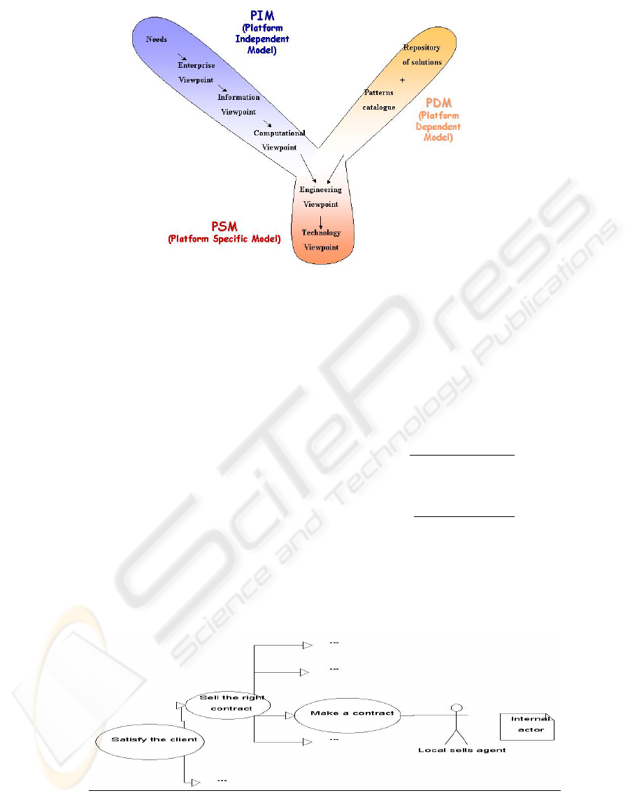
Figure 1: DASIBAO steps within an MDA framework
The concepts used in our method are all included in
models of the I.S., DASIBAO being MDA
compliant. The models are platform independent,
(left side of the figure) or platform dependant (lower
part of the figure).
DASIBAO steps can be followed in the order shown
above, but the architect can also iterate when
needed.
How to build a system architecture with DASIBAO,
what models are to be produced will be illustrated
here by an example dealing with customer
relationship. This example deals with the way the
enterprise can improve relationship with customers,
from the management of the various kind of contacts
to the enforcement of the contract. We will only
focus here on the contracting aspect.
3.1 Enterprise Viewpoint
Designing an I.S. generally addresses first business
questions, such as what are the IS objectives, who
are the actors, what are the constraints, the enterprise
viewpoint. At this stage, the aim is to obtain a
specification of the business that the system will
support.
3.1.1 Objectives and actors
First the main business objective of the system is
stated. Then it is refined into sub-objectives, until
atomic objectives are obtained, i.e. of a functionally
relevant granularity. Finally, for each atomic
objective, the
enterprise object responsible for
fulfilling this objective is named. Whether it is an
actor (i.e. it takes an active part) or a resource (i.e.
just a necessary mean) is then specified. A UML use
case diagram is produced (see figure 2).
Figure 2: Objectives and actors
ICEIS 2004 - INFORMATION SYSTEMS ANALYSIS AND SPECIFICATION
256
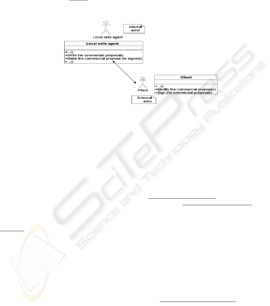
3.1.2 Actions and interactions
For each enterprise object of the previous step
playing an internal role, the
actions achieved by the
object in order to fulfill its objectives are identified.
For each of these actions, it is specified whether it is
an internal action for the enterprise object
considered, or an interaction between this enterprise
object and another one. Moreover, for each
interaction with an enterprise object that is out of the
system, the return interaction achieved by this
enterprise object should be defined when needed. A
UML class diagram is produced (see figure 3).
Figure 3: Actions and interactions
3.1.3 Behavior
The behavior of the system is then described, that is
to say the business processes the system supports.
The behavior consists in chaining the actions and
interaction identified in step #2 in an UML activity
diagram.
3.1.4 Constraints
Finally, the enterprise policies are defined : policies
on the enterprise objects, on their actions, and on the
system as a whole is defined. In this step, the non
functional constraints are specified, in order to end
with the most relevant scenarios.
Example :
Policy : Local sells agent can work on their temporary
disconnected portable computers and modify the
contracts they manage from a phone.
Non functional constraint : The system must follow
the server administration policies decided by the I.S.
department.
At the end of the enterprise viewpoint, we have
specified the functional objectives of the system.
Each atomic objective maps with an enterprise
object, that implements actions to fulfill it. The
global behavior of the system is then specified by
chaining these actions. It is also important to give a
precise description of the constraints on the system,
so that you can, at each further stage of the
DASIBAO method, look back to this step to check
them. At this stage the enterprise view point offers a
two-tier vision of the system : on one hand the
actions organized by responsibility, on the other
hand the chain of the actions within the framework
of a enterprise process.
3.1.5 Information Viewpoint
The aim of the information viewpoint is to describe
the
semantic of the information manipulated by the
system and the
semantic of the processing that
modify this information. We here propose to prepare
the groups that will be the business components of
the computational viewpoint.
3.1.6 Information objects
The information objects modified or used by the
internal actions of each enterprise object are
identified by examining the label of the actions : for
each verb, the noun that complements the verb is
usually an information object. Then the attributes of
the information objects and the relationship that
exist between them are defined. A UML class
diagram is produced.
Finally,
composite information objects are defined,
that is to say groups of information objects that can’t
exit independently. Doing so introduces reusable
business components. The information objects can
be grouped at 2 levels : relevant reusability level for
the enterprise or relevant grouping for the project
SPECIFYING INFORMATION SYSTEM ARCHITECTURES WITH DASIBAO - A standard based method
257
itself. A criteria for grouping can be based on the
kind of relationship previously established between
the information objects (e.g. composition,
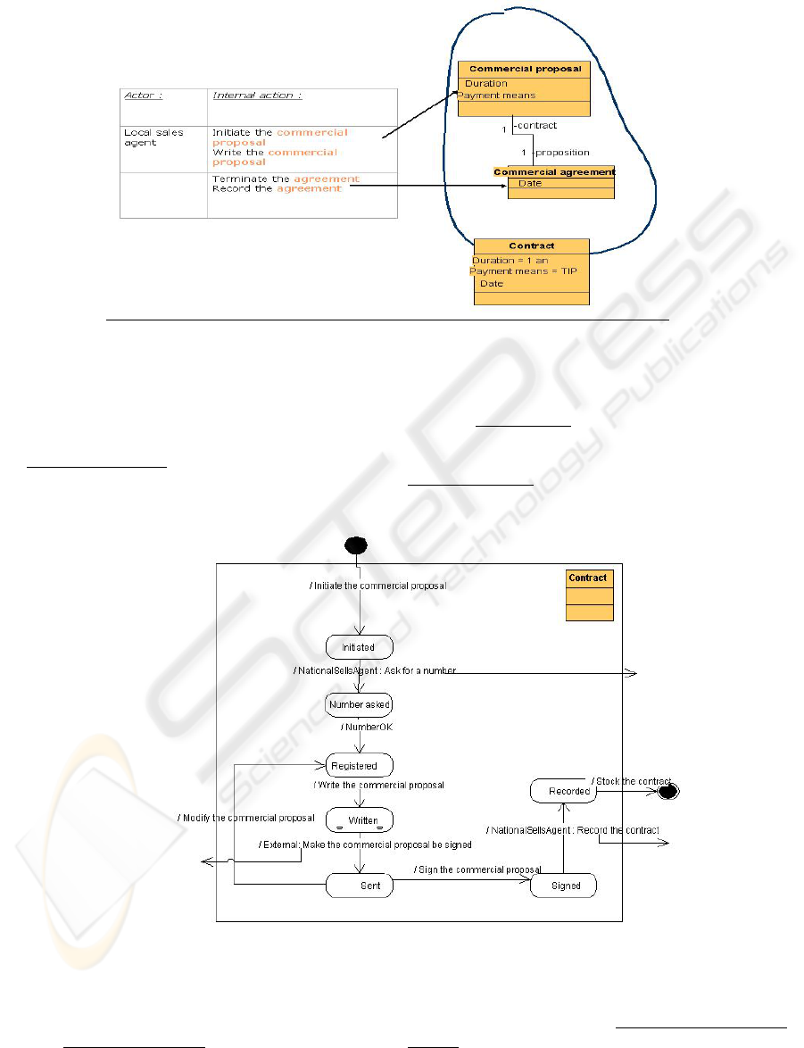
cardinality, etc…) (see figure 4).
Figure 4: Information Objects
3.1.7 Invariant schema, Static schema and
dynamic schema
The invariant schema is defined, specifying the
constraints (coherence, integrity…) that are to be
checked on the composite information objects.
These constraints can be inferred from the enterprise
policies.
Then the static schema describing the particular state
of the system (start, restart…) is defined.
Finally, for each composite information object, its
dynamic schema describing its different possible
states is specified (see figure 5).
Figure 5: Dynamic schema
At the end of the information viewpoint, we have
identified
information objects thanks to the actions
of the enterprise objects. These information objects
have been grouped into
composite information
objects announcing business reusable components.
We have then described more precisely their
ICEIS 2004 - INFORMATION SYSTEMS ANALYSIS AND SPECIFICATION
258
behavior with invariant, static and dynamic schemas.
3.2 Computational Viewpoint
The aim of the computing viewpoint is to create and
describe business components that will interact to
implement the business processes. We first specify
these components in a neutral environment, then we
assemble them in the specific context of the project.
3.2.1 Computational objects
For each composite information object, a
computational object is created and its interactions
with the environment are inferred from the actions
previously defined for the enterprise objects (see
figure 6).
+RecevoirDemande()
+Initialiser()
+DemanderNuméro()
+Rédiger()
+Amender()
+FaireSigner()
+RecevoirAmendement()
+RecevoirSignature()
+Finaliser()
+Enregistrer()
+Stocker()
-Identifiant
-Compte
-Durée
-Mode de paiement
Contrat
+DemanderNuméro()
+CréerNuméro()
+NuméroOK()
+Enregistrer()
+CréerArchiveContrat()
-IdentifiantContrat
-IdentifiantRégion
Archive de Contrats
Figure 6: Computational Objects
Using the policies defined in the enterprise
viewpoint, the functional constraints on these
computational objects are specified.
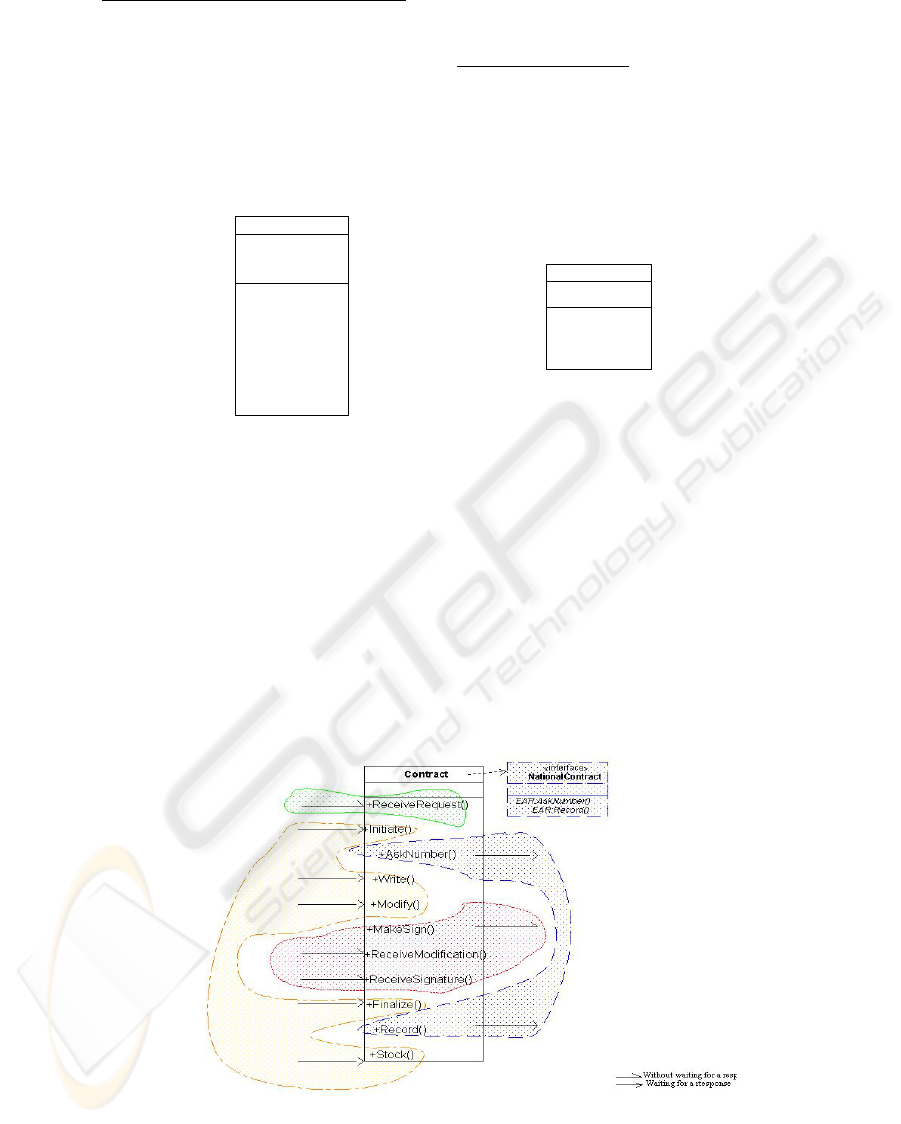
3.2.2 Interfaces
For each interaction, the type of the interaction is
determined : whether it is sending or receiving a
message, and whether it is waiting an answer or not.
The computational objects interfaces are then
defined. An interface is a group of interactions
classified on the “waiting for a answer or not”
criteria, which has consequences on the
synchronization of the interface. The interactions
can also be grouped if they have the same concern.
For each interface, the interface contract is specified
: constraints like pre-condition, post-conditions and
invariant on the interactions of the group. For
instance, it may indicate the type of interface
expected at the other end, the order of the signatures
and the response delay of the component. A UML
class diagram with UML interface stereotype is
designed (see figure 7).
Figure 7: Interfaces
3.2.3 Binding components
The interactions between the computational
components are inferred from the behavior (actions)
of the enterprise objects (see figure 8).
SPECIFYING INFORMATION SYSTEM ARCHITECTURES WITH DASIBAO - A standard based method
259
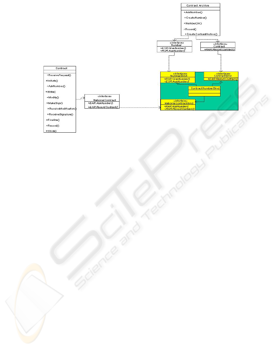
Figure 8: Binding components
For each of these interactions, a binding component
(object and interfaces) is created to support the
binding between the interfaces of these
computational objects.
For each binding component, the binding contract is
specified from the enterprise policies, concerning the
transparency constraints, the sequencing,
synchronism or delays constraints for the process.
3.2.4 Computational object behavior
The computational objects behavior is specified,
showing the binding components between the
business components, therefore designing the
process implementation.
At the end of the computational viewpoint, we have
defined the interfaces of the computational objects
by grouping their interactions, so that the object and
its interfaces compose now a business component.
Once we have studied each business component
obtained independently from the others, we
assemble them with binding components in order to
implement the business process.
At this stage, the specification here is composed of
models independent of any technical platform, i.e. a
MDA PIM.
3.3 Engineering viewpoint
The functional architecture we have specified in the
three previous viewpoints prepares the technical
architecture we will now start to specify in the
engineering viewpoint. We here merge the PIM with
platform models (MDA PDM) to obtain a platform
specific model of the system (MDA PSM). The
PDMs used by DASIBAO are mainly architecture
patterns and an EDF technical repository.
Unlike the computing viewpoint model, the
engineering model is not concerned with the
semantics of the distributed application, except to
determine its requirements for distribution.
The aim of engineering viewpoint is to specify from
the computational viewpoint two models. The first
one, the assembly model, describes the behaviour of
the generic engineering solution. The second model,
the deployment model, describes the dynamic
organisation in space and time of the components.
It is both models which allow to analyse the non-
functional qualities of the system.
The formalism we use here could be UML
components, but we have chosen, because of its
shortness, a component/connector type formalism
(see figure 9).
ICEIS 2004 - INFORMATION SYSTEMS ANALYSIS AND SPECIFICATION
260
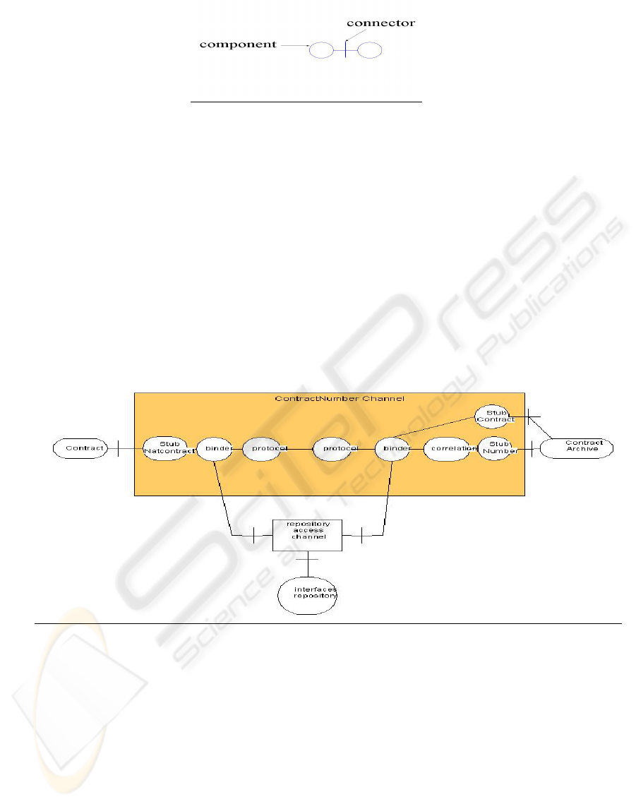
Figure 9: Component/connector formalism
3.3.1 Infrastructure and mechanisms for
communication, distribution and
transparency : Assembly model
First, the basic engineering components are created
(object and its interfaces), as the translation of the
computational components. Then, the engineering
components that support the services given to the
basic engineering components are identified. These
components will allow to implement the services
constraints listed on the computational components.
Then the engineering components, named channels,
implementing the binding components of the
computational viewpoint are identified. Each
channel is detailed as far as necessary into
engineering components needed to enforce the
transparency and protocol constraints specified in
the binding contract of the computational viewpoint.
Here, the architect can use patterns, based for
instance upon standards like CORBA, J2EE or .Net,
or even the “Stub/Binder/Protocol” RM-ODP
proposes.
The engineering components that, outside the
channel, support the channel components are also
listed (see figure 10).
Figure 10 : Channel components
Using the previous step, the channel between the
basic engineering component and its service support
engineering components can be specified, as well as
the channel between the channel and the
transparency support engineering components.
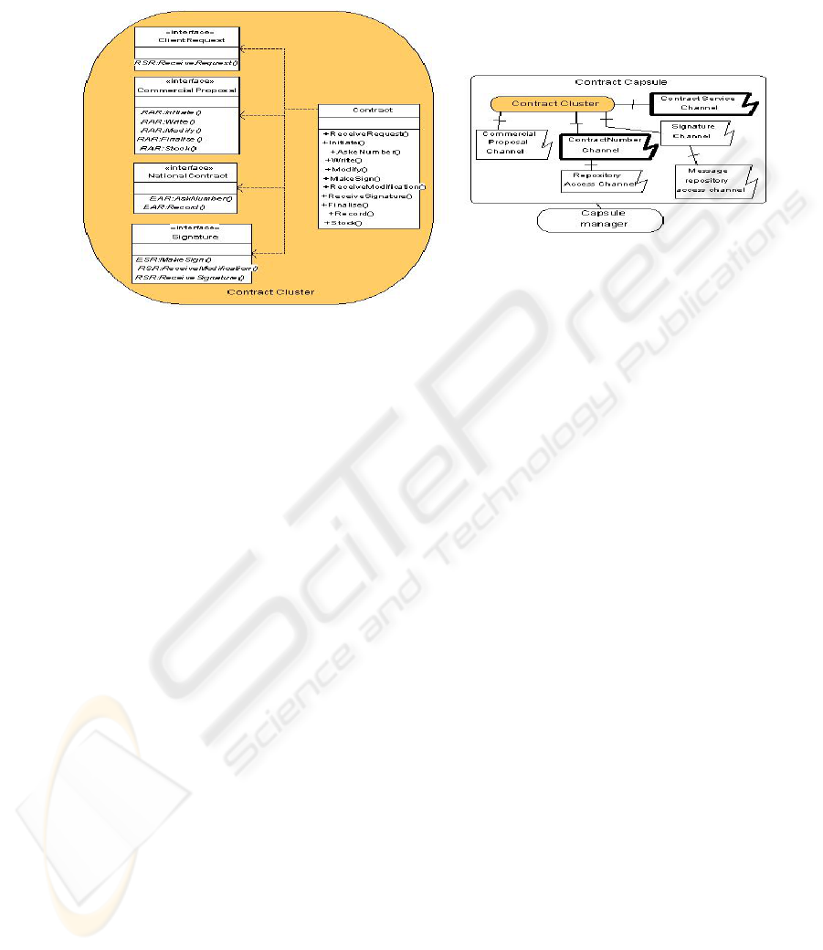
3.3.2 Deployment infrastructure :
Deployment model
The deployment infrastructure is based on one of the
patterns given by RM-ODP : a node contains a
kernel and capsules, and a capsule contains clusters
and half of the channels, and finally the cluster
contains basic engineering components.
The basic engineering components that have to
always be together for activation and migration
reasons are grouped in the same cluster. For each
cluster, a cluster manager is defined, that deals with
activation and deactivation, migration and other
specific operations.
Then the clusters that have the same needs for
allocation and protection are grouped in the same
capsule. For each capsule, a capsule manager is
defined, that deals with the clusters and the clusters
managers.
Finally, the nodes, i.e. the abstraction of addressable
SPECIFYING INFORMATION SYSTEM ARCHITECTURES WITH DASIBAO - A standard based method
261
entities on the network are defined. The components
in a same node share processing, storage and
communication resources. For each node, a kernel
that offers the basic components the access to these
resources is defined (see figure 11).
Figure 11: Deployment model
At the end of the engineering viewpoint, we have
obtained an infrastructure enabling communication,
distribution and transparency, based on basic
engineering components and channels with service
support engineering objects. We also have an
infrastructure to deploy the engineering components
into clusters, capsules and finally nodes.
3.4 Technology viewpoint
The technology viewpoint ends the technical
architecture specification by implementing the
system on a technical target, conforming to
Engineering viewpoint and respecting Enterprise
policies.
The softwares satisfying the specification of the
engineering viewpoint, either in the enterprise
repository or outside, can be now chosen.
Finally the servers and clients are dimensioned in
terms of computation capacity (number of
transactions per second), of RAM (number of
simultaneous process, number of simultaneous
connections), of ROM (see figure 12).
ICEIS 2004 - INFORMATION SYSTEMS ANALYSIS AND SPECIFICATION
262
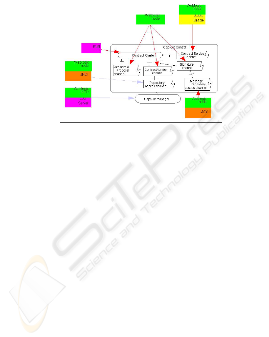
Figure 12: Technology model
The technology viewpoint leads to a detailed
technical architecture, that can be directly
implemented. The models we finally get are
completely platform specific models (MDA PSMs).
4 CONCLUSION AND FURTHER
WORKS
The architecture method described here, adapted
from the ISO/RM-ODP standard and according to
MDA principles, gives guidelines to system
architects from users needs to system
implementation. DASIBAO progressive steps help
to choose between architecture scenarios and to keep
track of these choices, thanks to the models
produced. This track enables to assess the impacts of
any environment evolution and to limit them to bare
minimum.
DASIBAO also allows to identify reusable business
components, and to transform them into technical
components.
EDF Research and Development Center has already
used DASIBAO in several projects. Some projects
have used part of the method, for instance
P@L/Salome, a distributed architecture for scientific
codes or OSGE, I.S. of EDF statistics. Some other,
starting after the method is available (July 2002),
have been able to use it as a whole, for instance
TRAMs, a platform using model transformation.
Taking advantage of a long experience in the field of
methodology and being implemented in various
domains (scientific, business, statistics…), this
method has proved its robustness and usability.
Moreover, DASIBAO is on its start to be
progressively used at EDF on a large scale. Most
developers have become more or less familiar with
the use of models but usually for description
reasons. Specifying system architecture with UML
and making use of different UML models to
streamline those specifications are clearly expected
improvements for developers, but imply some
change in customs.
Two main subjects will be further concerns for EDF
Research and Development Center about the
DASIBAO method.
On one hand we aim at supplying a complete catalog
of useful patterns of architecture (
architectural
figure). The objective is to take into account the quality
attributes during the selection of architecture and
propose some helps for bridging the gap between the
functional architecture and the technical architecture.
This implies to work on the use of the pattern
models in the engineering viewpoint and to explicit
model transformations underlying this use.
On the other hand we will
focus on the business
process aspect and in particular the use of
Workflow tools. The objective is to propose a formal
description of the process in order to ensure the
correctness when specifying the binding component
at the computational stage. This will lead us to deal
with model interoperability as well as with model
transformation.
SPECIFYING INFORMATION SYSTEM ARCHITECTURES WITH DASIBAO - A standard based method
263

REFERENCES
(Bedu, 2000) P. Bedu, 2000. Etude et conception
d’architecture. In Note EDF R&D avril 2002.
(Blanc, 1999) X. Blanc, M.P. Gervais and R. Le Delliou,
September 1999. Using the UML Language to Express
the ODP Enterprise Concepts. In Proceedings of the
3rd International Enterprise Distributing Object
Computing Conference (EDOC'99), IEEE Press (Ed),
Mannheim, Germany,
(Blanc, 2001a) X. Blanc, M-P. Gervais, R. Le Delliou,
2001. On the Construction of Distributed RM-ODP
specifications. In Proceeding of the Third IFIP
International Working Conference on Distributed
Applications and Interoperable Systems (DAIS 2001).
(Blanc, 2001b) X. Blanc, R. Le Delliou, June 2001.
Information System architecture with RM-ODP: an
on-the-field experience. In Proceeding of the Open
Distributed Processing: Enterprise, Computation,
Knowledge, Engineering and Realisation
(WOODPECKER 2001). pp27-37.
(Buschmann, 1996) Frank Buschmann, Regine Meunier,
Hans Rohnert, Peter Sommerlad, Michael Stal, 1996.
Pattern Oriented Software Architecture - A System of
Patterns. In Wiley 1996
(Cheesman, 2001).John Cheesman, John Daniels, 2001.
UML Components : A Simple Process for Specifying
Component-Based Software. In Addison-Wesley.
(D’Souza, 1999).Desmond Francis D’Souza, Alan
Cameron Wills, 1999. Objects, Components and
Frameworks with UML : The Catalysis Approach.
Addison-Wesley.
(EDF R&D I22 group, 2002) EDF R&D I22 group, 2002.
L'Architecture des Systèmes d'Information dans les
Projets Informatiques : Recueil théorique et pratique.
In Working document 2002.
(Garlan, 2000) David Garlan, Robert T. Monroe, and
David Wile, 2000. Acme : Architectural Description of
Component-Based Systems, Foundations of
Component-Based Systems. In Gary T. Leavens and
Murali Sitaraman (eds), Cambridge University Press, ,
pp. 47-68
(Gervais, 2002) M.P. Gervais, January 2002. ODAC : An
Agent-Oriented Methodology Based on ODP. In
Journal of Autonomous Agents and Multi-Agent
Systems, Kluwer Publishers.
(Herzum, 2000).Peter Herzum, Oliver Sims, 2000.
Business Component Factory : A Comprehensive
Overview of Component-Based Development for the
Enterprise. In Wiley Computer Publishing.
(IEEE, 2000) IEEE, 2000. Recommended practice for
architectural description of software-intensive
systems. In IEEE Std 1471.
(ISO, 1995) ISO, 1995. Open Distributed Processing-
Reference Model Part 1, 2, 3, 4. In ISO/IEC IS 10746-
1, 2, 3, 4, ITU-T Rec.X901, 2, 3, 4.
(ISO, 2002) ISO, May 2002. Open Distributed Processing
Reference Model –Enterprise Language. In ISO/IEC
IS 15414
(ISO, 2003) ISO, 2003. Open Distributed Processing-
Reference Model-Use of UML for ODP viewpoints
specifications. In Working Draft ISO/IEC 19793.
(Kazman, 1998) Rick Kazman, Mark Klein, Mario
Barbacci, Tom Longstall, Howard Lipson, Jeromy
Carrière, 1998. The architecture tradeoff analysis
method. In ICECCS98.
(Kruchten, 1995) Philippe Kruchten, 1995. The 4+1 View
Model of Architecure. In IEEE Software 12(6),
November 1995, 42-50.
(Nguyen, 2002) HQ Nguyen , L.Duchien, Ph. Bedu, J.
Perrin, 2002. Achieving technical architecture with
architectural figures. In IASTED Cambridge 2002
(OMG, 2001a) OMG, 2001. Model Driven
Architecture : Architecture board ORMSC. In OMG
ormsc/2001-07-01.
(OMG, 2001b) OMG, 2001. Relationship of the UML to
the RM-ODP. In OMG Version 1.4.
(Putman, 2001) J-R. Putman, 2001. Architecting with RM-
ODP. In Prentice-Hal.
ICEIS 2004 - INFORMATION SYSTEMS ANALYSIS AND SPECIFICATION
264
