
UML vs. IDEF: AN ONTOLOGY-ORIENTED COMPARATIVE
STUDY IN VIEW OF BUSINESS MODELLING
Ovidiu Noran
School of Computers and Information Technology, Griffith University
Nathan (Brisbane) QLD 4111 Australia
Keywords:
Expressive power, modelling language, business modelling, UML, IDEF, ontologies, metamodels, modelling
methodologies, Object-Oriented Analysis and Design.
Abstract:
The UML and IDEF sets of languages characterize typical modelling approaches of software engineering
and computer integrated manufacturing, respectively. This paper presents a comparative analysis of these
languages based on their ontologies and in view of their use in business modelling. A brief introduction
to UML and IDEF is followed by a high-level comparison taking into account underlying paradigms and
language structure. This is followed by a comparative assessment of the expressive power of the two groups
of languages, based on the ontologies of their relevant components. The analysis is structured using a set of
views deemed appropriate for the modelling domain (i.e. business). The key findings of this paper aim to
provide an insight into the suitability of UML ’versus’ that of IDEF in business modelling.
1 INTRODUCTION
1
The survival of businesses in today’s demanding
global market greatly depends on their agility, i.e.
their capability to respond adequately and timely to
changes in the environment. Agile businesses typi-
cally thrive on such changes by implementing their
own, continuous internal transformation processes.
Business models help promote a deep understand-
ing of the business and can support its operation
2
. A
business model is based on an ontology of changeand
as such it is an enabler of business agility. Busi-
ness modelling aims to produce models that accu-
rately reflect aspects of the business required for the
intended use of the models, and which are understood
by the target audience. Thus, the models must strike
a balance between complexity and expressiveness, re-
flected in the choice of modelling frameworks, lan-
guages and methodologies involved in the modelling
effort.
The complexity of the modelled targets often
brings about the necessity to use a set of candidate
1
the full version of this paper with additional compari-
son aspects and a proposed assessment framework may be
obtained from the author ( http://www.cit.gu.edu.au/˜noran)
2
e.g. by means of model-based control
languages for developing business models. Also, the
often-perceived failure of the software system to ac-
curately reflect the business that it supports has re-
sulted in calls for the same set of languages to be
used in modelling both the business and its informa-
tion system.
This paper makes a contribution towards an
ontology-oriented comparison of the suitability and
expressive powers of two candidate sets of languages
for the purpose of business modelling, namely the
Unified Modelling Language (UML) and the Inte-
grated DEFinition (IDEF) family of languages. Both
sets of languages may be used to model aspects of a
business, although they provide different degrees of
support for the various views involved in the business
modelling effort. This comparative analysis intends to
help the enterprise architect understand the available
options, and thus make an informed choice of mod-
elling languages for a specific business engineering
task.
674
Noran O. (2004).
UML vs. IDEF: AN ONTOLOGY-ORIENTED COMPARATIVE STUDY IN VIEW OF BUSINESS MODELLING.
In Proceedings of the Sixth International Conference on Enterprise Information Systems, pages 674-682
DOI: 10.5220/0002629306740682
Copyright
c
SciTePress
2 INTRODUCTION TO IDEF AND
UML
2.1 IDEF
The IDEF (originally an acronym for ICAM DEF-
inition) family of languages has its origins in the
1970’s US Air Force Integrated Computer Aided
Manufacturing (ICAM) program, which aimed to cre-
ate computer-implementable modelling methods for
analysis and design (Menzel and Mayer, 1998). As
shown in Table 1, after the initial project which
yielded IDEF0 (NIST, 1993a; IEEE, 1998), IDEF1
and IDEF2, there have been another two initia-
tives that have produced IDEF1X (IDEF1 eXtended)
(NIST, 1993b), and IDEF3 (Mayer et al., 1993),
IDEF4 and IDEF5, respectively.
The current efforts within IDEF are focused on the
refinement and integration
3
of the existing languages,
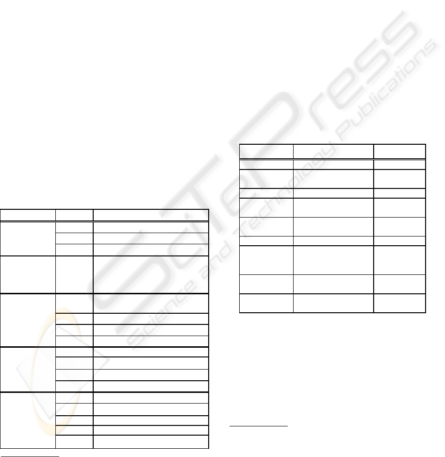
and the development of few others (see Table 1).
The currently most used IDEF languages are
IDEF0, IDEF1X and IDEF3. A complete introduc-
tion to the IDEF family of languages is beyond the
scope of this paper, but comprehensive IDEF infor-
mation is available
4
.
Table 1: The IDEF languages (based on (Cho, 2000))
!!
"#$
%
&
'(
#"""!!
) *+$,"
)-- .--*+$,"
/ *"!!
0 "1.!
2 3,""
4 '""".""
) 567"
8 "
! (
*9" (
& &,"( (" (
"
*.
#$
&
.
#$
"
!
3
hence the IDEF acronym shift from ICAM DEFinition
to Integration DEFinition
4
white papers on IDEF languages and methods are cur-
rently available on www.idef.com and www.kbsi.com.
2.2 UML
The Unified Modelling Language (UML) originates
in three modelling method streams, represented by
Booch (Booch, 1991), Jacobson (Jacobson, 1994)
and Rumbaugh (Rumbaugh et al., 1991). UML has
been subsequently complemented by the Unified Pro-
cess (Jacobson et al., 1999) - a software develop-
ment methodology based on an iterative development
paradigm.
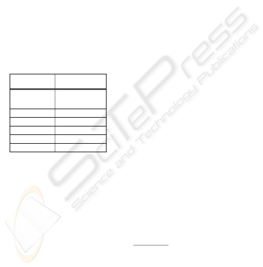
The UML is a set of essentially graphical languages
expressed as diagrams. The component languages
(refer Table 2) reflect the history of UML: created by
unification, rather than competition
5
. Despite their
syntax and semantics being defined in a set of meta-
models (Rumbaugh et al., 1999) and associated se-
mantics (OMG, 1999b), the languages composing the
UML are not completely formalised, and hence sub-
ject to interpretation
6
. A comprehensive description
of UML is beyond the purpose of this paper
7
.
Table 2: UML language components
!
"
!
" #
!
$%
!&
'
(
%
"#
(
3 A HIGH-LEVEL COMPARISON
3.1 Evolution
Both sets of languages have appeared at a suitable
time
8
and have had industry endorsement, either via
5
e.g. it has been argued that some of the UML languages
are somewhat redundant or overlapping in their scope.
6
precise UML (pUML, http://www.puml.org) is one ini-
tiative that aims to address such issues.
7
for more information refer (Rumbaugh et al., 1999)
8
IDEF has answered a need for computer implementable
Analysis and Design modelling methods/languages in man-
UML VS. IDEF: AN ONTOLOGY-ORIENTED COMPARATIVE STUDY IN VIEW OF BUSINESS MODELLING
675

government specification (IDEF) or merging of mod-
elling methods through developer, and end user par-
ticipation in a consortium (in the case of UML). IDEF
has preceded UML by nearly a decade, and while
as such it has had more time to mature, it has also
needed to adapt to historic changes in modelling re-
quirements. The ICAM project developing IDEF has
initially produced three languages aiming to model
the static, informational and dynamic aspects. How-
ever, various changes in the usage of analysis and de-
sign paradigms (such as a shift from Data- and Func-
tion Driven to Object-Oriented) has prompted a re-
finement of existing languages and the addition of
several new members to the IDEF family.
Currently, the IDEF suite numbers 16 languages,
of which 6 are actively used. It appears that some
languages have subsumed the scope of others (e.g.
IDEF3 has obsoleted IDEF2
9
and contains IDEF5 el-
ements; IDEF4 contains IDEF6 elements, and IDEF9
appears to have included most of IDEF6’s scope).
UML has started with a total of 9 diagram types
(languages), which have received minor revisions. A
formal constraint language has been developed for-
and included with UML. This has opened the way
towards removing some of its original ambiguities,
which also plagued its metamodel description. A
modelling process has been developed for the UML
users, and several extensions have been developed by
third parties for specific domains such as business
modelling, user interface design, etc, in effect creat-
ing extended modelling languages of which UML is
a common subset. Notably, several such customiza-
tions are based on ontologies of the IDEF family of
languages (such as e.g. the IDEF0-based extension
to the UML activity diagram for function modelling
(Eriksson and Penker, 1999)).
3.2 Modelling Approach
UML is based on the Object-Oriented Analysis and
Design (OOAD) (Shlaer and Mellor, 1988) method;
this strongly suggests the UML user to follow an OO
design method.
In IDEF, the business architect may choose to use
IDEF0, IDEF1/IDEF1X, IDEF3 and IDEF5 for Data-
and/or Function-driven analysis and design, or to use
such languages in order to enhance an OOAD per-
formed in IDEF4
10
(Mayer et al., 1995), which is
similar to Rumbaugh’s Object Modelling Technique
ufacturing, while UML has addressed calls for an integrated
OOAD set of languages in software engineering.
9
IDEF3 covers features of IDEF2, such as simulation
10
IDEF4 allows the migration of existing IDEF analysis
/ design models to an object-oriented form.
(Rumbaugh et al., 1991). Thus, the IDEF family gives
the user flexibility in the choice of the analysis and de-
sign languages and modelling methods (although cur-
rently, IDEF’s OO extensions are not widely used or
supported by modelling tools).
The IDEF family of languages offers components
(languages with associated methods) which allow tak-
ing a holistic approach to business modelling (such as
representing business artifacts in the context of life
cycle phases). On the UML side, the Unified Process
may also provide a life cycle modelling methodology.
3.3 Language Structure
A set of integrated languages must be based on a com-
mon metamodel that guarantees the consistency of its
components. The syntax and semantics of the IDEF
languages are separately described in their associated
documentation; however, IDEF developers have not
published a common metamodel underlying the com-
ponent languages. This is an significant drawback,
as typically the modelled business views are mutually
dependent. For example, the inputs / outputs of an
activity modelled in IDEF0 may be further detailed in
an IDEF1X data model. Activities modelled in IDEF0
may also appear as Units of Behaviour (UoBs), or as
triggers for changes of states in IDEF3 process flow
and state transition models respectively. As there ap-
pears to be no formal metamodel to enforce consis-
tency between the IDEF languages, a tool or set of
tools implementing several IDEF components (e.g.
IDEF0, IDEF1X and IDEF3) would have to provide
its own internal constraints to ensure coherence be-
tween the views modelled in these languages
11
.
In contrast, UML does have a common framework
underlying its languages and binding together the dia-
grams describing the various views constructed using
these languages. The component languages are de-
scribed in metamodels organised into a collection of
packages, which together form a unified UML meta-
model. Thus, a modelling tool claiming UML com-
pliance should be based on the UML metamodels and
semantics, as detailed in (OMG, 1999b).
The UML specification allows for its extension and
customization, which, when performed according to a
structured process recommended by the Object Man-
agement Group
12
, leads to UML profiles tailored for
a particular domain. This feature provides flexibility
but must be used with caution. Any extension to the
UML is in fact modifying its metamodel and hence,
11
a few modelling tools (e.g. Computer Associates’ ER-
Win/BPWin) do allow some integration of IDEF0, IDEF1X
and IDEF3 models.
12
OMG is the UML custodian, at www.omg.org
ICEIS 2004 - INFORMATION SYSTEMS ANALYSIS AND SPECIFICATION
676
its meaning to the intended audience. Thus, any such
modification must be properly documented and sup-
ported by a glossary, metamodel and preferably have
its semantics defined by a First Order Logic (FOL)
language; this will ensure that the models created with
the customised language are still comprehensible to
the target audience.
4 A VIEW-BASED COMPARISON
4.1 Choice of Views
Typical modelling views proposed by the software en-
gineering discipline (Si-Alhir, 1998) include Struc-
tural, Behavioural, User, Implementation and Envi-
ronment.
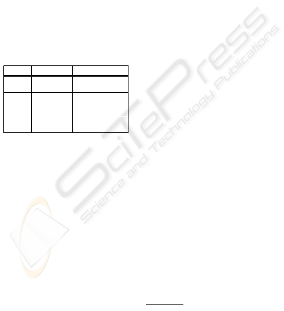
Table 3: Possible mapping of the views proposed by Soft-
ware Engineering and Manufacturing
!
"
Manufacturing and industrial automation propose
their own specific views, such as Function, Infor-
mation, Resources, Organisation, Manufacturing vs.
Control, Human vs. Non-human and Software vs.
Hardware (ISO/TC184/SC5/WG1, 2000).
The main requirement in the final selection of busi-
ness modelling views (shown in the left-hand side
of Table 3) has been that together, the chosen views
should be able to produce models usable by an analy-
sis and design process.
4.2 Ontology Capture
Capturing the ontology of a domain (e.g. business)
is a crucial step towards its effective modelling. Note
that generally, an ontology can be defined either to be
just a terminology (described e.g. by a meta-schema),
or to contain a theory (composed of terminology, ax-
ioms, constraints and inference rules) and operational
semantics. Thus, an information / data modelling lan-
guage may be employed to capture terminology (and
simple constraints such as cardinality / participation)
for an ontology, although it may reach its expressive
power limits
13
. Axioms, complex constraints and in-
ference rules must then be defined using an FOL lan-
guage.
UML does not provide a dedicated language for
ontology capture. However, UML class diagrams
(with or without extensions) can be used to par-
tially represent ontologies
14
(Cranefield and Purvis,
1999), while the Object Constraint Language (OCL)
(OMG, 1999a; Warmer and Kleppe, 1998) may be
employed to represent the axioms and more com-
plex constraints. Similarly, IDEF1 / IDEF1X may be
used for the purpose of partial ontology capture (with
limitations similar to UML class diagrams), com-
plemented by an FOL language such as Conceptual
Graphs (Sowa, 1998) or UML’s OCL.
IDEF5 is a specialised set of languages for the cap-
ture and construction of ontologies (Gruber, 1993).
This IDEF component uses a schematic language (re-
sembling an information modelling language) for a
first-cut ontology capture, and a more precise FOL
elaboration language (based on the Knowledge Inter-
change Format (Genesereth and Fikes, 1992)) for de-
scribing axioms, constraints and inference rules. The
IDEF5 specification also includes a methodology for
capturing ontologies (Mayer et al., 1994).
In conclusion, IDEF5 raises the expressive power
of the IDEF family for the purpose of ontology mod-
elling, while on the UML side formal extensions such
as ontology capture profiles may enhance UML’s ca-
pacity to capture ontologies.
4.3 Information / Data
Information is an essential and well-understood as-
pect of business modelling. Information/data
15
mod-
elling is typically performed at several levels (such
as conceptual, logical, physical
16
) before the result-
ing models are implemented in the information sys-
tem supporting the business. The comparative analy-
sis of IDEF and UML for information modelling pur-
poses must take into account such modelling levels,
the implementation and final purpose of the data mod-
els, and other environmental constraints (such as the
supporting infrastructure).
13
conversely, an ontology capture language may be used
to model information / data, albeit in a less efficient manner.
14
UML is already used in database schema and knowl-
edge models design (Schreiber, 1999)
15
in this context, data is seen as objective facts compos-
ing the Universe of Discourse, while information is the sub-
jective meaning associated to the data by users.
16
presently there is no unanimously accepted terminol-
ogy describing data modelling levels.
UML VS. IDEF: AN ONTOLOGY-ORIENTED COMPARATIVE STUDY IN VIEW OF BUSINESS MODELLING
677

Data modelling may be performed in UML using
its OO-based class diagrams, which contain entities
that may also encapsulate operations. Within IDEF,
the IDEF1 (information capture and modelling) and
especially IDEF1X (data modelling) languages, both
based on the Entity Relationship (ER) model (Chen,
1999) and early relational work by Codd (1970), have
traditionally been used to model information and data.
Specific concepts of IDEF1X and UML class di-
agrams (such as primary/foreign keys, weak entities
and relationships vs. object surrogate keys (OIDs),
qualified and basic associations) reflect their different
underlying paradigms, but provide equivalent expres-
sive power to the two languages. A specific feature of
the UML class diagrams (owing to the OO paradigm)
is their ability to express functional aspects of the
entities (classes) represented. This capability allows
class diagrams to be more expressive than IDEF1X if
needed, e.g. to represent constraints and triggers.
For a relational database application, IDEF1X may
be used to model data at conceptual and logical lev-
els; any special constraints can then be represented
by text or an FOL language. The resulting model
may then be represented at physical level in a rela-
tional data definition language (such as the Structured
Query Language - SQL) and implemented in the rela-
tional database. If UML class diagrams have to be in-
volved in modelling the conceptual and logical levels,
an OO to relational mapping should take place at log-
ical level, so that the result can still be implemented
in the relational database.
For an OO database application, the use of UML
class diagrams at the conceptual and logical levels
would facilitate the implementation of the resulting
model(s) in an OO data definition language. In this
OO-constrained scenario, IDEF1X may also be used
for modelling at conceptual and logical levels; how-
ever, the result must be subjected to a relational to OO
mapping
17
, resulting in an UML class diagram (or an-
other OO modelling language) model at logical level.
In the relational implementation scenario, UML’s
additional expressiveness is not fully utilised; thus,
IDEF1X may be a better choice, since it would not
require any additional mappings. Constraints (such
as referential integrity) will be represented in an
IDEF1X implementation by stored procedures and
triggers. In the OO implementation alternative, UML
class diagrams are an obvious choice since no addi-
tional mappings are needed and classes (and function-
ality) implemented in the OO database may be easily
17
attempts to define object-oriented extensions for
IDEF1X, ((Bruce, 1992), IDEF1X97) towards the purpose
of facilitating a transition from ER to OO have had little
impact, in view of the development of UML and IDEF4.
traced back to the conceptual level.
Both UML class diagrams and IDEF1X have ex-
pressiveness and consistency drawbacks. For exam-
ple, the IDEF1X notation meaning is dependent on
the context (with potential ambiguity and complex-
ity consequences
18
). The UML class diagrams on
the other hand allow distinct Object IDs for dupli-
cate objects, which may create data redundancy prob-
lems
19
. Both UML class diagrams and IDEF1X are
restricted to expressing binary relations / associations,
but since a ternary and higher order relation can al-
ways be turned into an ’objectified’ entity or class,
this does not limit the expressive power of either
UML or IDEF1X.
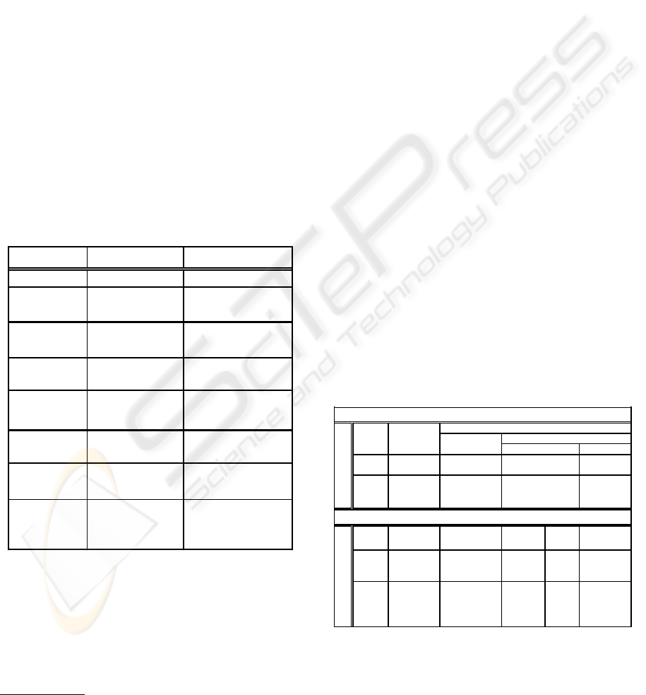
Table 4: Information / Data view comparison
!"#
$%&
'&
((
%
$
%
)"*$
'&
((
#
$
The IDEF4 Static models contain relationships
and links diagrams which are similar in meaning to
IDEF1X, However, IDEF4 static models also contain
inheritance and sub-typing diagrams which are simi-
lar to the UML class diagrams concepts (and thus pro-
vide an object-oriented modelling mechanism with
a comparable expressive power). Thus, the struc-
ture of IDEF4 static models (based on both the OO
and relational models) and the connection to IDEF1
/ IDEF1X allows it to also be employed in hybrid
(object-relational) database development. In addition,
IDEF4 facilitates the mapping of ER data models de-
veloped in the analysis/design phases to OO designs
(while all necessary models are contained and ex-
pressed in IDEF4).
Scope and space limitations do not allow a discus-
sion in depth of all aspects involved in modelling busi-
ness information and data.
18
e.g. in IDEF1X different symbols for a relationship’s
optionality are used depending on its cardinality; thus, a
symbol cannot represent independently the optionality and
cardinality of the entity next to it, but rather their combina-
tion (Hay, 1995)
19
for further details refer to (Ettlinger, 1999)
ICEIS 2004 - INFORMATION SYSTEMS ANALYSIS AND SPECIFICATION
678
4.4 Function
In the context of this paper, Function modelling is un-
derstood to subsume Activity and Behaviour (or Pro-
cess) modelling, whereby the behavioural aspect fur-
ther details and enriches the activity perspective (e.g.
with temporality, sequencing, states, etc).
4.4.1 Activity
This view of the business aims to describe the activ-
ities involved in the business (the ’what’), seeking to
abstract from the temporal aspect (i.e. succession, du-
ration, concurrency, etc). It is a well-understood and
researched aspect which appears in the large majority
of analysis and design methods.
Table 5: Activity view comparison
!
" #
$$$%
&"
'$ (
Note that the decisional aspect of a business may be
considered a specialisation of the activity sub-view.
Thus, an activity modelling language may be used to
model decisions. Specialised languages, more expres-
sive for the purpose of decisional modelling do exist
20
, however they are beyond the scope of this paper.
The UML component which is typically used to de-
tail the activity view of a business is the use case. Use
cases may be further decomposed and detailed (or
extended) to increase their expressive power (which
may, however, also result in high complexity). A sub-
set of the UML activity diagram may also be used
for activity modelling, provided that it contains no
timing-related features (such as synchronization or
explicit sequencing). Activity diagrams may be ar-
ranged into ’swimlanes’ so that they can be attributed
to ’roles’ (performers). Moreover, hybrid diagrams
are possible in UML (e.g. showing outputs for activ-
ities). Such features enhance the UML diagrams ex-
pressivity, although they should be properly explained
to the users and used in a consistent manner.
The IDEF component used for activity modelling
is IDEF0. Its ontology originates in the Structured
20
notably, GRAI Grids / Nets (Doumeingts et al., 1998)
Analysis Design Technique (Ross, 1987). IDEF0 di-
agrams contain Activities, which take ICOMs (In-
puts, Outputs, Controls and Mechanisms) and can be
decomposed in further IDEF0 diagrams. However,
IDEF0 lacks decision points and the possibility of ex-
pressing roles (Arnesen and Krogstie, 2002); in addi-
tion, some elements of its graphical notation may be
confusing
21
.
Such specific features of IDEF0 and UML activity
diagrams may enhance the expressiveness of a busi-
ness model produced within a specific modelling sce-
nario, depending on the particular expressive power
needs.
4.4.2 Behaviour
Behaviour is expressed in business modelling via
processes - ordered sequences of events aiming to
achieve a business outcome, usually within a sce-
nario.
UML provides use case diagrams for the high-level
definition of scenarios, and activity diagrams to de-
tail them. Sequence, Collaboration and State(chart)
diagrams may then be used to further specify be-
havioural models. In UML, dynamic behaviour may
also be modelled in other diagrams; e.g. a class di-
agram may contain invariants for active classes (or
for the whole model), pre-post conditions on opera-
tions of active classes, concurrency properties of op-
erations, or signal reception specifications. Signifi-
cant semantic variation points in the UML are related
to dynamic behaviour (such as statechart event queue
handling). Sequence and collaboration diagrams are
semantically equivalent (depict object cooperation in
a behaviour (Fowler and Scott, 2000)).
Behaviour is modelled in IDEF via IDEF3, which
captures precedence and causality relations between
situations and events; a process is a structured collec-
tion of activities related to one another by the tem-
poral constraints. IDEF3 contains decomposable Pro-
cess Flow Descriptions (PFDs, process-centric) and
Object State Transitions Descriptions (OSTDs, an
object-centric model of behaviour). An IDEF3 PFD
diagram usually covers a single use case scenario,
which is consistent with the typical coverage of an
UML sequence or collaboration diagram. This cover-
age equivalence facilitates a meaning-based (Larson,
1998) translation of an IDEF3 diagram to an UML se-
quence or collaboration diagram and viceversa. The
IDEF4 Dynamic model provides state diagrams and
client-server diagrams, which are similar to the UML
state diagrams and collaboration diagrams, respec-
21
such as the difference between Inputs and Controls, or
the meaning of tunnelled and bundled ICOMs
UML VS. IDEF: AN ONTOLOGY-ORIENTED COMPARATIVE STUDY IN VIEW OF BUSINESS MODELLING
679
tively. The IDEF4 and UML state diagrams use com-
mon concepts, such as events (to trigger state transi-
tions) and messages (to depict object collaboration).
IDEF4 also provides a specialised behaviour diagram,
describing implementation of messages in methods of
objects. Its notation is similar to the IDEF4 inheri-
tance diagrams and can thus be confusing.
UML activity diagrams are closest in their meaning
to the IDEF3 Process Flow Diagrams. Both languages
allow for decision points and synchronization. IDEF3
PFD’s Units of Behaviour are decomposable, allow-
ing the modeller to achieve a balance between expres-
siveness and model complexity suited to the specific
modelling purpose.
UML collaboration / sequence diagrams and
IDEF4 client-server diagrams express essentially the
same concept, i.e. how objects work together within
a given scenario. IDEF4 client-server diagrams can
represent object roles and attributes, while UML se-
quence / collaboration diagrams are able to represent
conditions, loops and nesting of the messages sent be-
tween objects.
Table 6: Behaviour view comparison
!
"#$
%&
"'
!
()
'
)
"*
$+
"
"'
%$,
-%(
"'
!$
$)&
$
)
"'
UML state diagrams, IDEF3’s OSTDs and IDEF4
state diagrams are all based on the Harel State Charts
(Harel, 1987). UML state diagrams can repre-
sent triggered or triggerless transitions and atomic,
composite- and history states
22
. In addition, UML
states can contain embedded variables and activities
(usable to connect to corresponding UML timed ac-
22
i.e. composite states that remember their active sub-
states when the object them (Rumbaugh et al., 1999).
tivity diagrams). IDEF3 OSTDs allow the representa-
tion of the triggering activities as IDEF3 UoBs, en-
abling a direct connection to the IDEF3’s Process
Flow Diagrams. Thus, IDEF3 PFDs and OSTDs can
represent activity-centric and object-centric views of
the modelled business behaviour within the same use
case. IDEF4 state diagrams can describe synchronous
/ asynchronous messages but also object communica-
tion, similar to UML sequence and collaboration dia-
grams. Table 6 synthesises these findings.
4.5 Resources
Business resources may be either information or other
artefacts - abstract (e.g. organisational unit), or phys-
ical (human or non-human, e.g. items).
The expressive power of UML class diagrams may
be enhanced for resources modelling by standard
extensions like stereotypes (e.g. <<Physical >>,
<<People >>, etc), tagged values and constraints,
or by specialised (resource-type) UML profiles (as
shown in Section 3.3). The use of UML at conceptual
and logical levels would facilitate an OO implemen-
tation of the resources database.
IDEF1/IDEF1X or IDEF4 static diagrams may be
used for resource modelling in a similar way to the In-
formation / Data view. The expressive power of these
languages may be enhanced by First Order Logic
(FOL) expressions or text at the conceptual / logical
level (which will be translated into stored procedures
/ triggers at the physical level in a relational resources
database implementation).
Table 7: Domain / view-based coverage of languages
!
"!
!
#
$
$%
&'
(
)
*
+
,!!
,
-
. /
. /
0"/,
#
. /1, '
2
3
-,
,
#
0"/,
/
$
$%
&'
(
(,
4.6 Organization
The organisational aspect of businesses is typically
not as well-understood as e.g. its functional, or in-
ICEIS 2004 - INFORMATION SYSTEMS ANALYSIS AND SPECIFICATION
680

formational facets. This makes organizational design
of a business a non-trivial exercise, which requires
expertise and substantial effort. To assist in this en-
deavour, various organisational patterns, essentially
representing reusable organisational reference mod-
els, (Eriksson and Penker, 1999; Keidel, 1999) have
been developed.
Typically, the business organisation view may be
obtained by mapping the resources (the who) on the
activities of the business (the what) This view may
even be considered a specialisation of the resources
view (where only resources that can do things are
represented).The organization model aims to show re-
source allocation, reporting methods and task assign-
ments.
Thus, business organisation may be modelled by
using UML class / object diagrams, or IDEF1X and
IDEF4 static diagrams, where for example classes (or
entities) are stereotyped to (or named as) organiza-
tional units. IDEF12 (as shown in Table 1) is a mem-
ber of IDEF family specialised for organisational de-
sign
23
; as for the UML, generic or specialised exten-
sions may be used to enhance organisational models.
A relational patterns repository may be modelled us-
ing e.g. IDEF1X, while a knowledge base containing
facts and rules (representing patterns) may be mod-
elled using UML class diagrams.
Other business organization aspects such as or-
ganizational behaviour, or the structure of decision
centres
24
may be modelled by representing organi-
zational units in the Behaviour view, or the Activity
view respectively.
5 CONCLUSIONS
This paper has performed an ontology-oriented anal-
ysis of the IDEF and UML sets of languages for the
purpose of business modelling
25
.
The expressive power of languages greatly depends
on the theoretical models underlying their compo-
nents. Some such models are limited
26
in their ex-
pressive power by their focus on a particular aspect of
the Universe of Discourse.
Extending a language with constructs and rules
suitable for specific modelling areas is likely to aug-
ment its expressive power. However, such extensions
must be properly documented, to ensure an unam-
biguous meaning to the end user. A metamodel of
23
the future of IDEF12 is not clearly defined as yet
24
organizational units seen from a decisional perspective
25
(Noran, 1999) holds a case study based on this analysis
26
such ’limitation’ may in fact help avoid unnecessary
model complexity.
the extended language should also be constructed and
used in order to ensure the consistency of the models
created, while FOL languages may need to be used
to define their semantics. Other factors also need to
be taken into account when creating language exten-
sions, such as user acceptance and training in the ex-
tended language.
In the case of IDEF, consistency between the mod-
els produced using its various languages has to be pro-
vided by the modelling tool or the user . UML may be
used for business modelling as-is, with the standard
extensions, or involving proprietary constructs (such
as described in (Eriksson and Penker, 1999)). UML-
provided extensions may reach their limits when
modelling a complex business, while dedicated exten-
sions bring about the necessity of glossaries, rigorous
metamodel control and FOL languages for semantics
definition.
Using the same set of languages to model the soft-
ware system and the business it supports is attractive
for two reasons. Firstly, if an accurate business model
can be used to derive the requirements for its infor-
mation system (Marshall, 1999), then these require-
ments are likely to closely reflect the actual needs of
the business. Secondly, if the same set of tools is used
in modelling the information system and the business,
then consistency may be easier to enforce across the
models, and users’ training can be effectively focused
on the set of tools which is actually used.
REFERENCES
Arnesen, K. and Krogstie, J. (2002). Comparing Languages
for Enterprise Modeling using a Language Quality
Framework. Norwegian University of Science and
Technology, Norway.
Booch, G. (1991). Object-Oriented Design With Applica-
tions. The Benjamin/Cummings Publishing Company,
Redwood City, CA.
Bruce, T. (1992). Designing Quality Databases with
IDEF1X Information models. Dorset House.
Chen, P. (1999). The entity-relationship model - towards a
unified view of data. ACM Transactions on Database
Systems, 1:9–36.
Cho, H. (2000). IDEF Overview. Manufacturing Systems
Integration Lab, Department of Industrial Engineer-
ing, Pohang University of Science and Technology.
Codd, E. (1970). A relational model for large shared data
banks. Communications of the ACM, 13:397–434.
Cranefield, S. and Purvis, M. (1999). Uml as an ontology
modeling language. In Proc. of the Workshop on In-
telligent Information Integration, 16th Int. Joint Con-
ference on AI.
UML VS. IDEF: AN ONTOLOGY-ORIENTED COMPARATIVE STUDY IN VIEW OF BUSINESS MODELLING
681

Doumeingts, G., Vallespir, B., and Chen, D. (1998). GRAI
grid decisional modelling. In Bernus, P., Mertins, K.,
and Schmidt, G., editors, Handbook on Architectures
of Information Systems, pages 313–339. Springer,
Heidelberg.
Eriksson, H.-E. and Penker, M. (1999). Business Modelling
with UML. John Wiley & Sons, New York.
Ettlinger, B. (1999). IDEF1X vs. UML: A comparative
analysis. Technical report, Information Technology
Division, N.Y. Power Authority, White Plains, NY.
Fowler, M. and Scott, K. (2000). UML Distilled. Addison-
Wesley, Reading, MA.
Genesereth, M. and Fikes, R. (1992). Knowledge inter-
change format version 3.0 - reference manual. Report
Logic-92-1, Logic Group, Stanford University, CA.
Gruber, T. (1993). A translation approach to portable on-
tologies. Knowledge Acquisition, 2, 2:199–220.
Harel, D. (1987). Statecharts: A visual formalism for com-
plex systems. Science of Computer Programming, 8.
Hay, D. (1995). A comparison of data modelling tech-
niques. The Database Newsletter, 23.
IEEE (1998). Standard for function modelling language -
Syntax and semantics for IDEF0, IEEE 1320.1:1998.
ISO/TC184/SC5/WG1 (2000). ISO/IS 15704: Industrial
automation systems - Requirements for enterprise-
reference architectures and methodologies. ISO/IS.
Jacobson, I. (1994). Object-Oriented Software Engineer-
ing: A Use Case Driven Approach. Addison-Wesley,
Reading, MA.
Jacobson, I., Booch, G., and Rumbaugh, J. (1999). The Uni-
fied Software Development Process. Addison-Wesley,
Reading, MA.
Keidel, R. (1999). Seeing Organisational Patterns. Berrett-
Koehler Publishers, Inc, San Francisco, CA.
Larson, M. (1998). Meaning-Based Translation: A Guide
to Cross-Language Equivalence. University Press of
America, Inc.
Marshall, C. (1999). Enterprise Modelling with UML - De-
signing Successful Software Through Business Analy-
sis. Addison-Wesley, Reading, MA.
Mayer, R., Benjamin, P., Menzel, C., Fillion, F., deWitte, P.,
Futrell, M., and Lingineni, M. (1994). IDEF5 ontol-
ogy capture method report. Technical report, Wright-
Patterson AFB, Wright-Patterson AFB, OH.
Mayer, R., Keen, A., Browne, D., Harrington, S., Marshall,
C., Painter, M., Schafrik, F., Huang, J., Wells, M.,
and Hisesh, H. (1995). IDEF4 object-oriented design
method report. Technical report, Wright-Patterson
AFB, Wright-Patterson AFB, OH.
Mayer, R., Menzel, C., Painter, M., deWitte, P., Blinn, T.,
and Benjamin, P. (1993). IDEF3 process descrip-
tion capture method report. Technical report, Wright-
Patterson AFB, Wright-Patterson AFB, OH.
Menzel, C. and Mayer, R. (1998). The IDEF family of
languages. In Bernus, P., Mertins, K., and Schmidt,
G., editors, Handbook on Architectures of Information
Systems, pages 209–241. Springer, Heidelberg.
NIST (1993a). Integration definition for function modelling
(IDEF0). Technical report, Computer Systems Labo-
ratory, National Institute of Stds and Technology.
NIST (1993b). Integration definition for information mod-
elling (IDEF1X). Technical report, Computer Systems
Laboratory, National Inst of Stds and Technology.
Noran, O. (1999). Business modelling: UML vs. IDEF.
Technical report, School of Computers and Informa-
tion Technology, Griffith University, Brisbane, Aus-
tralia. Available at http://www.cit.gu.edu.au/˜noran.
OMG (1999a). Object Constraint Language Specification,
version 1.3. Framingham, MA.
OMG (1999b). UML Semantics v1.3. Framingham, MA.
Ross, D. (1987). Structured analysis (sa): A language for
communicating ideas. IEEE Transactions on Software
Engineering, 3:16–34.
Rumbaugh, J, ., Jacobson, I., and Booch, G. (1999).
The Unified Modelling Language Reference Manual.
Addison-Wesley, Reading, MA.
Rumbaugh, J., Blaha, M., Premerlani, F., Eddy, F., and
Lorensen, W. (1991). Object-Oriented Modeling and
Design. Prentice-Hall, Englewood-Cliffs, NJ.
Schreiber, G. (1999). Knowledge Engineering and Manage-
ment. MIT Press.
Shlaer, S. and Mellor, S. (1988). Object-Oriented Systems
Analysis: Modeling The Real World in Data. Prentice-
Hall, Englewood-Cliffs, NJ.
Si-Alhir, S. (1998). UML in a Nutshell. O’Reilly, Se-
bastopol, CA.
Sowa, J. (1998). Conceptual graphs. In Bernus, P.,
Mertins, K., and Schmidt, G., editors, Handbook on
Architectures of Information Systems, pages 287–311.
Springer, Heidelberg.
Warmer, J. and Kleppe, A. (1998). The Object Constraint
Language: Precise Modelling with UML. Addison-
Wesley, Reading, MA.
ICEIS 2004 - INFORMATION SYSTEMS ANALYSIS AND SPECIFICATION
682
