
FROM ONTOLOGY CHARTS TO CLASS DIAGRAMS
semantic analysis aiding systems design
Rodrigo Bonacin
1
, M Cecilia C. Baranauskas
1
, Kecheng Liu
2
1
Institute of Computing, State University of Campinas, Caixa Postal 6176 13083 970 Campinas, SP - Brazil
2
Department of Computer Science, University of Reading, Reading, RG6 6AY, UK
Keywords: Organisational Semiotics, Semantic Analysis, UML, Unified Process
Abstract: Despite the wide adoption of the Object Oriented paradigm for software development and the usefulness of the
Unified Modelling Language, there still are aspects of business modelling not well captured and
represented. Previous literature in Organisational Semiotics has shown that its methods could facilitate a
converging process for reaching a semantic representation, which delivers an agreed business model. In this
paper we define a process for informing UML class diagrams with results of Semantic Analysis. We provide
a group of heuristic rules to aid the construction of a preliminary class diagram from an ontology chart.
1 INTRODUCTION
Information and communication technologies are the
new power for innovation in companies nowadays.
The approach to the design of these technologies is
crucial for the adequacy of a technological artefact
in organisational contexts. Although there are
successful applications of technological artefacts in
organisations, there are also many stories of fails
(Booch, 1998). In order to cope with this problem
researchers have been developing new
methodologies and pointing out that the process for
designing systems for the organisational context is
still too far from being a solved problem.
According to Xie et al. (2
003, pp. 89)
“Understanding the business itself is the foundation
for any successful software development. For the
information systems analysts and designers,
successful communication with the domain experts
so as to properly understand, interpret, and apply
their business knowledge into software design and
implementation has always been a challenging part
of the job.”
During the last years, new standards have
e
merged in the software industry. Particularly the
standards based on the Object Oriented (OO)
approach became the most diffused after the
popularisation of the OO programming languages.
The Unified Modelling Language (UML) (OMG,
2003) is nowadays widely used for OO modelling by
system analysts, designers and developers. The RUP
(Kruchten, 1999), a specific and detailed instance of
a more generic process, the Unified Process (UP),
introduced by Jacobson et al. (1999) became also
widely used by the software industry.
The RUP captures many practices in software
d
evelopment paradigm from the Business Modelling
to the Deployment of the system. Nevertheless,
literature in the Organisational Semiotics (OS) have
pointed out some weaknesses of applying the
traditional modelling approach based on an
objectivist view to business modelling (Liu, 2000;
Stamper, 2000; Xie et al., 2003).
Assuming that the semiotic approach ca
n
contribute with improvements in business
modelling, we can have both: the organisational
semiotics with a different and valuable view of the
organisation on one hand and a de facto industrial
standard based on the OO approach on the other
hand.
In line with Xie et al. (
2003) who argue that
Organizational Semiotics can improve the OO
modelling, in this paper we propose steps and
heuristic rules to construct a preliminary version of a
class diagram based on outcomes from the Semantic
Analysis Method (SAM). The paper is organised in
the following way: Section 2 presents the theoretical
background; Section 3 discusses and shows how
SAM could inform the construction of class
diagrams; and Section 4 concludes.
389
Bonacin R., Cecilia C. Baranauskas M. and Liu K. (2004).
FROM ONTOLOGY CHARTS TO CLASS DIAGRAMS - semantic analysis aiding systems design.
In Proceedings of the Sixth International Conference on Enterprise Information Systems, pages 389-395
DOI: 10.5220/0002631103890395
Copyright
c
SciTePress

2 THEORETICAL BACKGROUND
2.1 The Semantic Analysis Method
In opposition to the objectivism, which presupposes
that there exists a world independent of the observer,
an objective reality composed by a structure of pre-
existent entities, the SAM is based on the
subjectivist paradigm (Liu, 2000), which
understands reality as a social construct based on the
behaviour of agents participating on it.
The building blocks of the Semantic Analysis
involves the concepts of affordance, ontological
dependency and agent.
Affordance, the concept introduced by Gibson
(1979) can be used to express the invariant
repertories of behaviour of an organism made
available by some combined structure of the
organism and its environment. In Semantic Analysis,
affordances are social constructs in a certain social
context (Liu, 2000). The social world acts as the
environment that is constantly affecting the agents’
behaviour, and is affected by the agents’ actions.
An ontological dependency is formed when an
affordance is possible only if certain other
affordances are available. We say that the affordance
“A” is ontological dependent on the affordance “B”
to mean that “A” exists only when “B” does.
An agent is a special kind of affordance, which
can be defined as something that performs
responsible behaviour. An agent can be an
individual person, a cultural group, a language
community, a society, etc.
The SAM addresses issues that are not
represented in any of the UML diagrams and it
provides a different way of thinking about the
organisation if compared with the Object Oriented
paradigm.
2.2 The OO Support for Business
Modelling
In the set of UML models, one diagram can support
the construction of another providing different views
of the system. According to the official UML
specification (OMG, 2003, pp. 46): “The choice of
what models and diagrams one creates has a
profound influence upon how a problem is attacked
and how a corresponding solution is shaped. (…) No
single view is sufficient”.
In the Rational Unified Process (RUP) the
business modelling has two major parts (OMG,
2003, pp. 587; Ng, 2002): (1) The business use-case
model describes the business processes and their
interaction with external parts as a sequence of
actions; (2) The business object model describes
business processes from an internal perspective.
“Whereas a business use-case model tells what a
business process will do, a business object model
tells how it will be done. It serves as an abstraction
of how business workers and business entities need
to be related and to collaborate in order to perform
the business” (Heumann, 2001, pp. 3).
2.3 Previous work on Organisational
Semiotics allied to Object
Orientation
Xie et al. (2003) have argued that RUP could be
improved with the semantic and norm analysis.
Applying RUP in a case study, they identified some
problems in business modelling that Organisational
Semiotics could help to understand and improve.
These problems are related to: “Facilities to
rigorously analyse and define the meanings of the
business entities, use of notations that help to reach
and disseminate the common understanding of the
business entities, method to reveal the fundamental
and essential relationships among the business
entities, method for responsibility-oriented workflow
analysis, criteria for the level of detail of the activity
descriptions and criteria for the termination of the
iterations” (Xie et al., 2003, pp. 94)
To maximize the benefits of SAM to the UP, we
need a method to build OO diagrams from the
concepts worked by Semantic Analysis. Liu (2000)
presented some principles of transformation from
SAM to an OO design. In other work Liu and Xie
(2003) have proposed a mapping from some
structures of the ontology chart to a class diagram:
(1) Agents and Affordances can be mapped to
Classes and some can be mapped to methods of
classes; (2) Regarding Ontological dependencies,
they can be mapped to: nested classes; the dependent
class can be included by value in the antecedent
class; the dependent can be contained in the
antecedent class as one of its methods; model the
antecedent as parameters of a method; (3) Role
names are mapped to inherited classes; (4)
Determiners are mapped to either classes or
attributes of classes.
3 BUILDING UML CLASS
DIAGRAMS INFORMED BY
SAM
We highlight the differences between the ontology
chart and the UML based business models in two
ICEIS 2004 - INFORMATION SYSTEMS ANALYSIS AND SPECIFICATION
390
aspects: (1) while the RUP business models describe
the business process, the semantic analysis is not
focusing a process view, but a description of the
organisation’s signs and the relations among them,
and (2) we have different concepts in the OO
approach and SAM and consequently the models
show different representations of reality;
In this work we review fundamental concepts
and define a process for informing the UML class
diagram with results of SAM. We provide a
sequence of steps and a group of heuristic rules to
construct a preliminary class diagram from an
ontology chart.
The proposed approach was generated and
refined during the development of Pokayoke: a
CSCW system for supporting problem solving in a
manufacturing organisation (Bonacin and
Baranauskas, 2003). This system was designed using
the Semiotic Participatory Method (SPaM),
integrating Participatory Design and Organisational
Semiotics techniques (Bonacin and Baranauskas,
2003).
3.1 Heuristics to construct Class
diagrams from Ontology Charts
We are proposing four steps to the construction of a
first version of a class diagram: (1) from the
affordances names, create a table of potential classes
and operations; (2) model the relations between
classes and operators from the relations in the
ontology chart; (3) model the attributes from the
determiners, and (4) give names to associations and
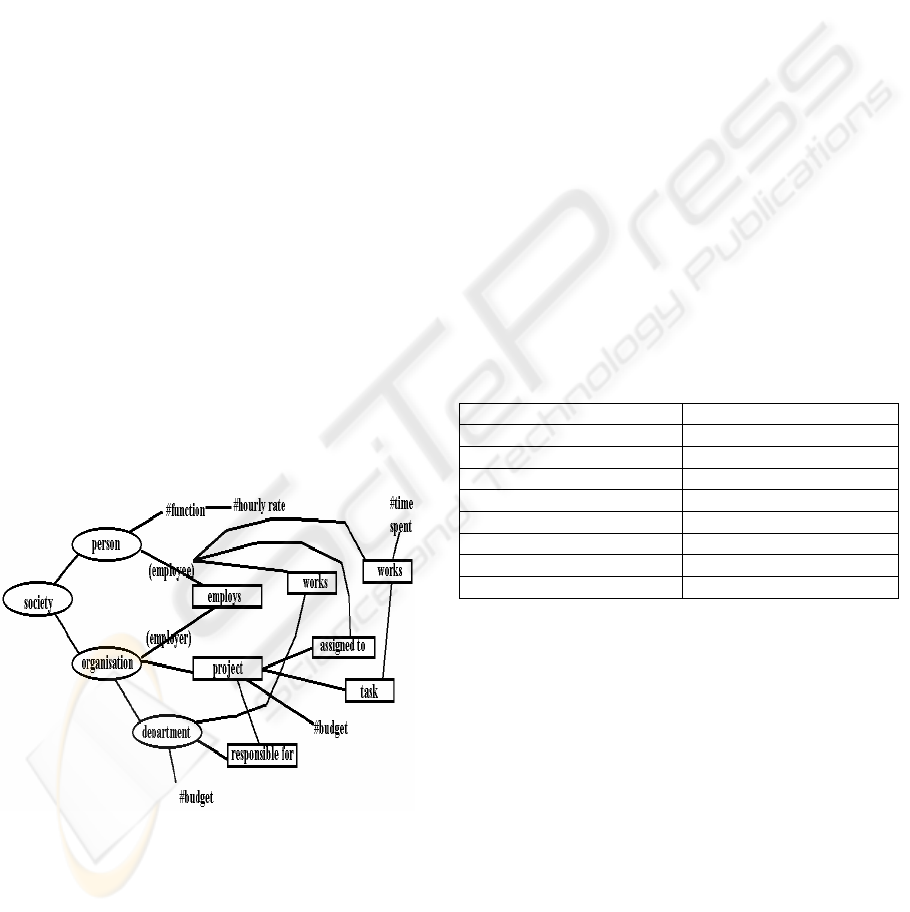
reorganise the class diagram if necessary. Figure 1
is an example of an Ontology Chart used to illustrate
the proposed steps and rules.
Starting the OO modelling after working in
Semantic Analysis, the first question to be answered
is “Where are the objects in the semantic diagrams?”
The presence of affordances in the ontology chart
suggests classes to be modelled in the class diagram;
e.g.: a department in the SAM perspective is an
affordance of the society and in the OO perspective
it is an object with internal attributes and operations.
If the affordance department is represented in the
ontology chart this suggests, from the OO
perspective, that there is such object in the context
and we can refer to this class of objects using the
name “department”. As a first heuristic we suggest
that affordance names that are “nouns” should be
translated to classes. Figure 1 shows some signs that
refer to objects from the OO perspective: society,
organisation, department, person, employee,
employer and task.
After listing some potential objects to be part of
an initial class diagram, “what do the other
affordances suggest?” For example, works is an
affordance and it could be seen as an operation of
some object, from the OO perspective. The presence
of works in the ontology chart suggests that there is
some class with the operation works. As a second
heuristic we suggest that the affordance names that
are “verbs” should be translated to operations.
A table with the potential classes and operations,
as shows Table 1, is the outcome of step 1.
Table 1: Potential Classes and Operations
Potential Classes Potential Operations
Society Works
Organisation Assigned to
Department Employs
Person Works on
Employee Responsible for
Employer
Project
Task
Step 2 involves to discover the relations among
the classes and operations to construct a first version
of a class diagram. The ontology chart can suggest
some relations among the concepts of the table; e.g.:
there is an ontology dependency between the
affordances society and person in Figure 1, and they
are classes in Table 1. The ontology dependency
suggests that there is an association between them.
“Why does the ontological dependency suggest
this kind of relation?” From the OO perspective we
could say that the object derived from the dependent
affordance (e.g. person) is created and destroyed
during the existence of the object derived from the
antecedent affordance (e.g. society). This
interpretation suggests that the object person is
possible only if the object society is also possible.
This kind of “existential” dependence cannot be
directly represented in the class diagram, since this
Figure 1: Ontology chart for project management
(
from Liu, 2000,
pp
. 79
)
FROM ONTOLOGY CHARTS TO CLASS DIAGRAMS: SEMANTIC ANALYSIS AIDING SYSTEMS DESIGN
391

diagram do not specify when the objects are
constructed and destroyed. The use of UML
behaviour diagrams could represent lifecycle
dependency (this dependency can be stored in a list
of lifecycle dependencies and used later). As a third
heuristic we propose to model an association
between classes, whenever one object cannot exist if
another does not exist.
The case described in the last paragraph is only
one of possible cases of relations among the
elements of the group of potential classes and
operations. We have identified 10 other different
cases. Tables 2 to 5 describe the heuristic rules to be
applied for each case and the rationale behind the
rule. These cases are distributed in four groups:
Group A (Table 2). Rules to be applied to
relations between affordances whose names are
“nouns” in the ontology charts. For example, in
Figure 1, we have: society-person, society-
organization, person-employee, organization-
employer, organization-department, organization-
project and project-task;
Table 2: Rules of Group A
Rule Rule Description, Example and Rationale
a.i
If the relation is a “whole-part” in the ontology chart then the
class diagram will have a composition. (e. g. the affordance
department is part of organisation in the ontology chart and in the
class diagram organisation will be composed of department).
A whole-part relationship means that an affordance is not only
part of its antecedent but also that is ontologically dependent on
it. In OO an aggregation represents that one object is part of
another. We propose the use of “composition”, a special kind of
aggregation, which specifies the composite object is responsible
for the creation and destruction of the parts. Therefore the
lifecycle of the “part” is enclosed in the lifecycle of the composite
object.
a.ii
If the relation is “ontological dependency” there is an
association between the corresponding classes. The existential
dependency must be represented in the behaviour diagrams. (e.g.
the affordance problem is ontologically dependent on
organisation; the class diagram will have an association between
problem and organisation; the behaviour diagram of the class
problem is instantiated and destroyed only if it exists an object of
the class organisation).
An “ontological dependency” means that the dependent
affordance is only possible if we have the antecedent. From the
OO perspective we could say that the object derived from the
dependent affordance should be created and destroyed during the
existence of the object derived from the antecedent. This kind of
dependence cannot be represented in the class diagram, because it
does not specify when the objects are constructed or destroyed.
This is the reason why we propose the use of behaviour diagrams
to represent it. We also propose to model an association between
the classes.
a.iii
If the relation is a “role-name”, the class corresponding to the
role name will be a subclass of the antecedent and will have an
association with the dependent (if the dependent can not be
operation of the role name class). (e.g. the role-name employee is
dependent on person and employs; then, in the class diagram the
employee will be a sub-class of person and will have a relation
with the class that contains the operation employs)
A “role-name”, means that an agent has a specific role. From
the OO perspective we could have the object that was derived
from the “role-name” as a specialisation of the antecedent In
some cases another alternative is the use of the OO concept of
“role” .
a.iv
If the relation is a “specialisation”, it can be translated to a
hierarchic relation in the class diagram. (e.g. natural person and
corporate body are specific terms to legal person; in the class
diagram the natural person and corporate body will be sub-
classes of person).
A “specialisation” in the SAM perspective means that we have
one generic affordance and the specialised ones. In the OO
perspective we have an object that is the generic one and another
that is the specialised one, this concept is modelled as a hierarchic
relation in the class diagram.
Group B (Table 3). Rules to be applied to
relations between affordances where the antecedent
name is a “noun” and the dependent name is a
“verb”. For example, in Figure 1, we have:
employee-works, department-works, employee-
works on, task-work on, department-responsible for,
project-responsible for, project-assigned to and
employee-assigned to;
Table 3: Rules of Group B
Rule Rule Description, Example and Rationale
b.i
If the relation is an “ontological dependency” we have two
options: (1) the operation corresponding to the dependent
affordance will be part of the class definition corresponding to
one of its antecedents, or (2) if it is already part of some class, the
class diagram will have an association between this class and the
class corresponding to the antecedent affordance. The choice of
which class will contain the operation is made according to the
OO principles (e.g. walk can be an operation of people). The
existential dependency will be represented in the behaviour
diagrams. (e.g. the affordance walk is dependent of person and
surface; in the class diagram the walk will be operation of person
and an association between person and surface will be modelled
in the behaviour diagram; no execution of the method walk is
possible without an object of the class surface).
If the operation (from the dependent affordance) is part of the
definition of the class (from the antecedent affordance) the
operation is only possible if the class is possible, since there is not
operation without a class in the OO approach. If the operation is
already part of the definition of another class we propose an
association between the classes, because the operation (from the
dependent affordance) is only possible if a certain class (from the
antecedent affordance) is possible. The class diagram does not
specify when the objects are constructed and destroyed; for that
we propose the use of behaviour diagrams to represent it.
b.ii
If the relation is a “specialisation”, the class diagram will have
the specific (in the ontology chart) as operation of the generic.
(e.g. a generic affordance attitude have the specific affordances
desire, want and like; in the class diagram the class attitude will
have the operations desire, want and like)
A “specialisation” means that we have one generic affordance
and other specialised. We have not this kind of hierarchal relation
between a class and an operation in the class diagram. We
propose that the operation could be modelled as an operation of
the generic one because it suggests that they could have common
behaviour
ICEIS 2004 - INFORMATION SYSTEMS ANALYSIS AND SPECIFICATION
392

Group C (Table 4). Rules to be applied to
relations between affordances with a “verb” as
antecedent and the dependent is a “noun”. An
example of this group could be (this case did not
show up in Figure 1): the affordance error is
ontologically dependent on the affordance notify;
Table 4: Rule of Group C
Rule Rule Description, Example and Rationale
c.i
If the relation is an “ontological dependency” the class diagram
will have an association between the class (from the dependent)
and the class where the operation was specified. The existential
dependency will be represented in behaviour diagrams. (e.g. the
affordance error is ontologically dependent on notify, then there
will be an association between the class that notify is part (e.g.
mail server) and the error class)
The fact of an object exist only if an certain operation exist can
be interpreted as the object has to be created and destructed
during the operation execution (possible by chain of methods
invocations). This fact can be represented by the behaviour
diagrams of UML and invocations between classes suggest
associations between classes in the class diagram
Group D (Table 5). Rules to be applied to
relations between affordances whose names are
“verbs” in the ontology charts. An example of this
group could be (this case did not show up in Figure
1): the affordance stumble is ontologically
dependent of the affordance walk.
Table 5: Rules of Group D
Rule Rule Description, Example and Rationale
d.i
If the relation is a “whole-part”; we have two options: (1) if the
operations are part of the same class, the operation from the
antecedent will invoke the other operation, and (2) if they are part
of different classes, there will be a link between the two classes,
and the antecedent will invoke the other operation. (e.g. a part of
the affordance register (as verb) is fill out; the class diagram
could have register and fill out as part of the same class (e.g.
person), and the behaviour diagram reflects that the execution of
fill out is only possible during the execution of register)
A “whole-part” relation means that an affordance is part of
another in the SAM. From the OO perspective it could mean that
an operation is part of another operation. We propose that an
operation invoke (may be not directly) the other operation
because the invoked operation is part of the whole operation. This
aspect will be represented in the behaviour diagrams of UML. If
they are specified in different classes, we propose an association
between the classes
d.ii
If the relation is an “ontological dependency” we propose apply
the same of rule “d.i”. (e.g. the affordance stumble is
ontologically dependent on walk; in the class diagram will have
walk and stumble as part of the same class, and the behaviour
diagrams will reflect that the execution of stumble is only possible
during the execution of walk)
From the OO perspective an operation exists only if another
operation also exists. A method should execute only if another
method is also executing; for this reason we propose that the
operation from the antecedent should invoke (may be not directly)
the other operation. This aspect will be represented in the
behaviour diagrams of UML. If they are specified in different
classes we propose an association between the classes
d.iii
If the relation is a “specialisation”, we have two options: (1) if
generic and the specific affordances was translated to operations
of the same class, the specific could use the generic one in its
execution, (2) if the generic and the specific are translated to
operations of different classes, it can suggest a hierarchic relation.
(e.g. the affordance move and the specialisations walk and run; if
they are translated to the same class (e.g. person) run could
invoke the move)
In the OO perspective we could have an operation that is
generic and another operation that is the specialised one. In the
class diagram there is not hierarchic relation between operations.
The specific operation can use the generic operation to execute
some of the generic behaviour. If they are in different classes, it
could suggest that the classes have at least a common behaviour
for these operations
3.2 The Approach Illustrated
For the example of Figure 1, we could apply rule
(a.i) to represent the relations between organization-
department and project-task, rule (a.ii) to the
relations between society-person, society-
organization and organization-project; rule (a.iii) to
the relations person-employee and organization-
employer, and the rule (b.i) to the relations
employee-works, department-works, employee-
works on, task-work on, responsible-responsible for,
project-responsible for, project-assigned to and
employee-assigned to.
A class diagram generated from the applications
of the rules is the outcome of the step 2. The step 3
involves the translation of determiners to attributes
or classes. In Figure 1, the determiners function and
hourly rate were translated to attributes of employee
(see Figure 2). Determiners of affordances which
are verbs can be translated to variables of the
operations. Some determiners suggest the necessity
of new classes.
FROM ONTOLOGY CHARTS TO CLASS DIAGRAMS: SEMANTIC ANALYSIS AIDING SYSTEMS DESIGN
393
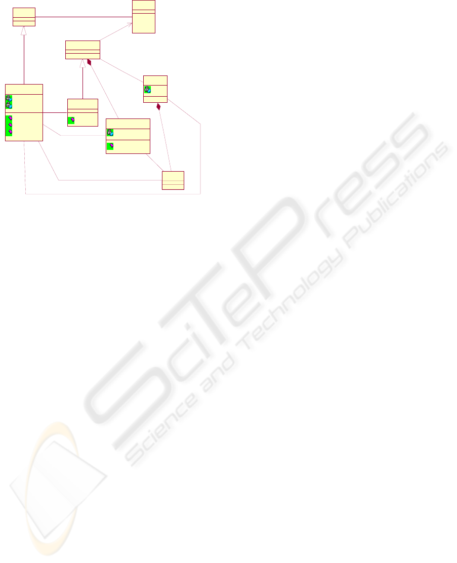
In the step 4 we propose to refine the class
diagram, by giving names to the associations and by
changing the position of the classes in the diagram
or by representing the directions of the associations.
For example an association between the
organisation and society classes could receive the
name “exits at” and the order could be changed to
facilitate reading from the OO perspective. The
choice of the association names depends on context
interpretation according to the OO perspective; for
example it is possible to give the name “have” to the
association between society and organization. Some
associations can have the same name of the
operations (e.g. works, works on and assigned to in
Figure 2), but this redundancy can be eliminated
later.
The proposed steps and rules have produced
consistent diagrams when applied to the Pokayoke
system development. It was a quick way to construct
OO models from the ontology charts. But, in some
cases the application of the rules includes the choice
of the adequate design options from the OO
perspective, and also a deeper analysis of the
produced diagram. For example: a role-name in the
ontology chart suggests a hierarchical relation or a
“role” in the class diagram. In Figure 1 the role-
name “employee” produced a subclass of person
and the role-name “employer” a subclass of
organisation (see Figure 2). We could represent the
employer as a role of the organisation in its
association with the employee. Sometimes these
relations became clear along the modelling work;
they are exceptions that we can dealt with and they
were rare in the Pokayoke context.
4 CONCLUSION
person
employer
employs()
depart ment
budget
responsible for()
task
responsable for
project
budgetemployee
function
hourly rate
works()
wor ks_on()
ass igned to()
have a
wo rk s
wo rk s o n
assi gened to
organisation
defi ne
society
live at
exists at
It has been generally agreed that business modelling
is the foundation for the design of successful
software applications. Previous literature in OS has
shown that there could be a valuable contribution of
OS methods to enhance business modelling.
This paper presented a sequence of steps and a
group of heuristic rules developed to construct class
diagrams based on ontology charts. By applying
them it is possible to produce a first draft of class
diagrams to be useful to an OO programming
approach. Further work should be done in order to
articulate the proposed approach with a broader view
of the UP. Also further research involves to develop
tools to support the construction of UML diagrams
informed by the SAM outcomes.
ACKNOWLEDGMENTS
Fi
g
ure 2: Class Dia
g
ram
p
roduce
d
This work was partially supported by grants from
Brazilian Research Council (CAPES BEX2214/02-
4, CNPq 301656/84-3 and FAPESP 2000/05460-0).
The authors also thank Delphi Automotive Systems
in Jaguariúna, Brazil, and the members of the AIS
Lab (University of Reading) for collaboration and
partnership.
REFERENCES
Bonacin, R. and Baranauskas, M. C. C., 2003, Designing
Towards Supporting and Improving co-operative
Organisational Work Practices. Proceedings of 5th
International Conference on Enterprise Information
Systems, v.3, 233-238.
Booch, G., 1998, Software Development Best Practices, in
The Rational Unified Process: an introduction, P.
Kruchten, Addison-Wesley, 3-16.
Gibson,J. J., 1968. The Ecological Approach to Visual
Perception. Houghton Miffin Company, Boston,
Massachusetts.
Heumann, J. , 2001, Introduction to Business Modeling
Using the Unified Modeling Language (UML), The
Rational Edge, Rational Software,
www.therationaledge.com
Jacobson, I., Booch, G. B. and Rumbaugh, J., 1999, The
Unified Software Development Process. Addison-
Wesley.
Ng, PW, 2002, Business Process Modeling and Simulation
with UML, The Rational Edge, Rational Software,
www.therationaledge.com
Kruchten, P., 1999, The Rational Unified Process.
Addison-Wesley.
ICEIS 2004 - INFORMATION SYSTEMS ANALYSIS AND SPECIFICATION
394

Liu, K., 2000. Semiotics in information systems
engineering, Cambridge University Press.
Liu, K. and Xie, Z., 2003, Applying Semantic Analysis: a
user’s view, Research report EPSRC-SEDITA project.
OMG, 2003, OMG Unified Modeling Language
Specification, Version 1.5. www.omg.org/uml
Stamper, R. K., 2000, Information Systems as a Social
Science: An Alternative to the FRISCO Formalism. In
Information System Concepts: an Integrated
Discipline Emerging, E. D. Falkenberg, K. Lyytien
and A. A. Verrijn-Stuart, eds, Kluwer Academic
Publishers, USA, 1-51.
Xie, Z., Liu, K., and Emmitt, D., 2003, Improving
Business Modelling with Organisational Semiotics, In
H.W.M. Gazendam, R. J. Jorna, R. S. Cijsonw (eds.)
Dynamics and change in Organizations - Studies in
Organizational Semiotics, Kluwer Academic
Publishers, 85-102.
FROM ONTOLOGY CHARTS TO CLASS DIAGRAMS: SEMANTIC ANALYSIS AIDING SYSTEMS DESIGN
395
