
ADVANTAGES OF UML FOR MULTIDIMENSIONAL MODELING
∗
Sergio Luj
´
an-Mora, Juan Trujillo
Department of Software and Computing Systems, University of Alicante
Carretera de San Vicente s/n, Alicante, Spain
Panos Vassiliadis
Department of Computer Science, University of Ioannina
Ioannina, Hellas
Keywords:
Multidimensional modeling, UML, data warehouses, multidimensional databases, OLAP, object orientation.
Abstract:
In the last few years, various approaches for the multidimensional (MD) modeling have been presented. How-
ever, none of them has been widely accepted as a standard. In this paper, we summarize the advantages of using
object orientation for MD modeling. Furthermore, we use the UML, a standard visual modeling language, for
modeling every aspect of MD systems. We show how our approach resolves elegantly some important prob-
lems of the MD modeling, such as multistar models, shared hierarchy levels, and heterogeneous dimensions.
We believe that our approach, based on the popular UML, can be successfully used for MD modeling and can
represent most of frequent MD modeling problems at the conceptual level.
1 INTRODUCTION
Data warehouses (DW), Multidimensional databases
(MDB), and On-Line Analytical Processing (OLAP)
applications relay on the multidimensional (MD)
paradigm. The basic underlying constructs of MD
modeling are facts, measures (fact attributes), dimen-
sions, and attributes (dimension attributes). The star
schema (Kimball, 1996) has been widely accepted
as the underlying logical construct of MD systems
(i.e., DW). However, there does not exist a precise
model for the conceptual modeling, although various
approaches for the conceptual design of MD systems
have been proposed in the last few years, such as
(Golfarelli and Rizzi, 1998; Sapia et al., 1998; Try-
fona et al., 1999).
On the other hand, the Unified Modeling Language
(UML) (Object Management Group (OMG), 2001)
has been widely accepted as the standard object-
oriented (OO) modeling language for describing and
designing various aspects of software systems. We
have previously proposed a MD modeling approach
based on the UML (Trujillo et al., 2001), which has
been recently formalized as a UML extension (Luj
´
an-
Mora et al., 2002a). We take advantage of the flexibil-
ity of the UML to elegantly represent main MD prop-
∗
This paper has been supported by a grant from the State
Secretary of Education and Universities (Spanish Ministery
of Education, Culture and Sport).
erties at a conceptual level. Our approach imposes a
three-layered schema that guides the designer in mod-
eling the MD schema and the final user in navigating
in the schema (Luj
´
an-Mora et al., 2002b).
The main contribution of this paper is to show how
to use together in a unified proposal our previously
presented partial solutions. Therefore, we show how
our approach resolves some important problems of
the MD modeling, such as multistar models, shared
dimensions, multiple and alternative hierarchy levels,
and heterogeneous dimensions. Furthermore, we also
compare the solutions that our approach provide with
other authors’ solutions.
The remainder of this paper is organized as fol-
lows. Section 2 discusses some related work. Sec-
tion 3 summarizes the basis of our OO conceptual
MD modeling approach based on the UML. Section 4
highlights the main situations where the use of UML
shows great advantages for MD modeling with re-
spect to other approaches. Finally, Section 5 presents
the main conclusions and introduces topics for future
work.
2 RELATED WORK
In the last few years, several MD data models have
been published. Some of them fall into the logical
level (such as the well-known star schema by Kimball
298
Luján-Mora S., Trujillo J. and Vassiliadis P. (2004).
ADVANTAGES OF UML FOR MULTIDIMENSIONAL MODELING.
In Proceedings of the Sixth International Conference on Enterprise Information Systems, pages 298-305
DOI: 10.5220/0002633302980305
Copyright
c
SciTePress

(Kimball, 1996)). Others, such as The Dimensional-
Fact (DF) model (Golfarelli and Rizzi, 1998), The
Multidimensional/ER (M/ER) model (Sapia et al.,
1998) and The starER model (Tryfona et al., 1999),
may be considered as formal models as they provide
a formalism to consider main MD properties. A re-
view of the most relevant logical and formal models
can be found in (Blaschka et al., 1998; Abell
´
o et al.,
2001).
However, none of the current conceptual modeling
approaches considers all MD properties at both the
structural and dynamic levels. Therefore, we claim
that a standard conceptual model is needed to con-
sider all MD modeling properties at both the struc-
tural and dynamic levels. We argue that an OO ap-
proach with the UML is the right way of linking struc-
tural and dynamic level properties in an elegant way
at the conceptual level.
3 MULTIDIMENSIONAL
MODELING APPROACH
BASED ON UML
In this section we summarize
2
our OO MD modeling
approach based on the UML. Our approach is based
on the one hand, in the use of package diagrams in
order to simplify huge and inter-related MD models,
and on the other hand, in a set of stereotypes
3
(FACT,
DI ME NS IO N, DESCRIPTO R, etc.) in order to repre-
sent the main structural properties of MD models.
3.1 Extending UML
UML is a general purpose modelling language that is
broadly applicable to different types of systems, do-
mains, methods and processes. However, there may
be situations in which the user might want to extend
the language in some controlled ways to tailor it to
specific problem domains. In anticipation of this situ-
ation, the UML provides a set of extensibility mecha-
nisms that allow us to customize and extend the UML
by adding new building elements (stereotypes), cre-
ating new properties (tagged values), and specifying
new semantics (constraints).
We have previously proposed a UML extension for
MD modeling (Luj
´
an-Mora et al., 2002a; Luj
´
an-Mora
et al., 2002b). In this paper, we unify our proposals
and present all the stereotypes together. In a UML
diagram, there are four possible representations of a
stereotyped element, e.g., the four representations of
2
A complete description of our approach can be found
in (Luj
´
an-Mora et al., 2002a; Luj
´
an-Mora et al., 2002b).
3
The stereotypes are highlighted in the text using a
SM ALL CA PS font.
a class with the FACT stereotype are shown in Figure
1: icon (the stereotype icon is displayed), decoration
(the stereotype decoration is displayed inside the el-
ement), label (the stereotype name is displayed and
appears inside guillemots), and none (the stereotype
is not indicated).
Figure 1: Different representations for a stereotyped class
3.2 Package Diagrams
A MD model can be very complex when the scale
of the MD system is large and includes a large num-
ber of interconnections among its different elements
(mainly facts and dimensions). In our MD modeling
approach, we use packages to group classes together
into higher level units creating different levels of ab-
straction, and therefore, simplifying the final model.
In this way, we avoid the use of flat diagrams, which
are usually confusing for both final users and design-
ers in most of the cases. We have divided the design
process into three levels (Figure 2 shows a summary
of our proposal):
Level 1 : Model definition. We use one package
stereotype called STA RPACKAG E that represents a
star schema of a conceptual MD model. A depen-
dency between two packages at this level indicates
that the star schemas share at least one dimension.
Level 2 : Star schema definition. We use two pack-
age stereotypes called FACTPACKAGE and DI-
ME NS IO NPACKAGE that represent a fact or a di-
mension of a star schema respectively. A de-
pendency between two dimension packages at this
level indicates that the packages share at least one
level of a dimension hierarchy.
Level 3 : Dimension/fact definition. A package from
the second level is exploded into a set of classes
that represent the hierarchy levels in a dimension
package, or the whole star schema in the case of
the fact package. We use three class stereotypes at
this level: FACT, DIM EN SI ON, and BASE.
3.3 Facts and Dimensions
In our MD modeling approach, the main structural
properties of MD models are specified by means of
a UML class diagram in which the information is
clearly separated into facts and dimensions. Facts and
dimensions are represented by FACT and DIMENSION
ADVANTAGES OF UML FOR MULTIDIMENSIONAL MODELING
299
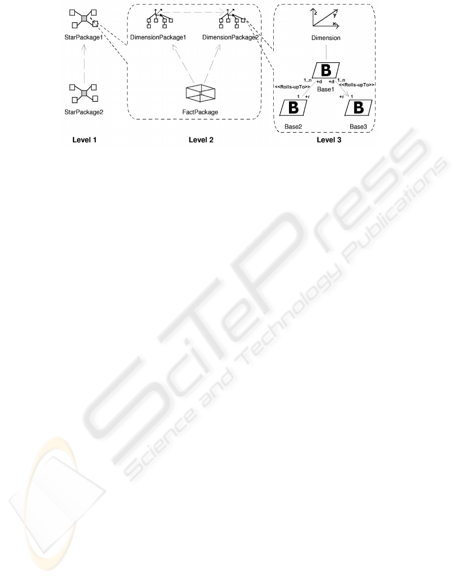
Figure 2: The three levels of a MD model.
classes, respectively. Then, FACT classes are speci-
fied as composite classes in shared aggregation rela-
tionships of n DIMENSION classes.
FACT classes consist of two kinds of attributes:
FACTATT RI BUTEs, which represent measures (the
transactions or values being analyzed), and DEGEN-
ER ATEDIMENSIONs (Kimball, 1996; Giovinazzo,
2000), that allow the DW designer to represent
other FACT features in addition to the measures for
analysis; DEGENERATEDIM EN SI ONs also facilitate
joins with On-Line Transaction Processing (OLTP)
databases.
With respect to dimensions, every classification hi-
erarchy level is specified by a class called BASE class
(see level 3 in Figure 2). A RO LL S-UP TO association
of BASE classes specifies the relationships between
two levels of a classification hierarchy; the roll-up
and drill-down direction of the association is repre-
sented by means of “r” and “d” roles on the ends of the
association. Our approach can represent both multi-
ple and alternative classification hierarchies. The only
prerequisite is that the hierarchy levels must define a
Directed Acyclic Graph (DAG) rooted in the DIMEN-
SI ON class. Every classification hierarchy level must
have a DE SC RIPTOR attribute; this attribute is nec-
essary for an automatic generation process into com-
mercial OLAP tools, as these tools store this informa-
tion in their metadata. The multiplicity 1 and 1..* de-
fined in the target associated class role addresses the
concepts of strictness and non-strictness, respectively.
Strictness means that an object at a hierarchy’s lower
level belongs to only one higher-level object. More-
over, defining an association as COM PL ET EN ES S ad-
dresses the completeness of a classification hierarchy.
By completeness we mean that all members belong
to one higher-class object and that object consists of
those members only. Our approach assumes all clas-
sification hierarchies are non-complete by default.
Finally, the categorization of dimensions, used to
model additional features for a class’s subtypes, is
represented by means of generalization-specialization
relationships. However, only the dimension class can
belong to both a classification and specialization hier-
archy at the same time.
4 ADVANTAGES OF UML FOR
MULTIDIMENSIONAL
MODELING
In this section we highlight the main situations where
the use of UML means a considerable advantage for
MD modeling regarding other approaches. To exem-
plify our approach, we will use a simplified version of
the warehouse example taken from (Kimball, 1996).
In this example, there are three separate inventory def-
initions within the same model, representing different
approaches of the inventory problem. The first ap-
proach is the inventory snapshot, which measures the
inventory levels in a regular period of time (every day,
every week, etc.). The second is the delivery status in-
ventory, which tracks the disposition of all the items
in a delivery until they leave the warehouse. Finally,
the third is the transaction inventory; in this case ev-
ery change of status of delivered products is recorded
throughout the deliver flow of the product.
4.1 Multistar Models
The multistar concept, also called fact constellation,
refers to the situation where a single MD model has
multiple facts, and therefore, creating multiple star
schemas. Basically, this structure is required when the
facts do not share all the dimensions (Kimball, 1996).
As commented in Section 3.2, our approach is
based on a three-layered model. At level 1, multi-
ple packages that represent different star schemas can
be specified. For example, in Figure 3, the first level
ICEIS 2004 - DATABASES AND INFORMATION SYSTEMS INTEGRATION
300
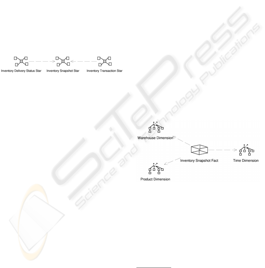
of the warehouse example is depicted. According to
our MD approach, we have defined three packages
that represent a star schema each one: Inventory De-
livery Status Star, Inventory Snapshot Star, and
Inventory Transaction Star. A UML dependency
(represented as a dotted line with an arrow) connect-
ing two packages indicates that one package uses el-
ements (e.g. dimensions, hierarchy levels) defined in
the other. The direction of the dependency indicates
that the common elements shared by the two packages
were first defined in the package pointed to by the ar-
row. To simplify the design, and therefore, reducing
the number of dependencies, we highly recommend to
choose a star schema to define the dimensions. Then,
other schemas can use them with no need to define
them again. If the common elements had been first
defined in another package, the direction of the arrow
would have been different.
Figure 3: Multistar multidimensional model.
4.2 Support for Different Building
Perspectives
There exist two “extreme” perspectives of building a
DW (Kimball, 1998):
• To build the whole DW all at once from a central,
planned perspective (the monolithic approach).
• To build separate subject areas (data marts) when-
ever is needed (the stovepipe approach).
Our MD modeling approach allows the user to ap-
ply any of these perspectives or a mixing of them.
Thanks to the use of the UML packages, the DW de-
signer can define the DW gradually or all at once.
Moreover, thanks to the UML importing mechanism,
the user can reutilize a concept defined in a package
in other packages.
For example, regarding the MD model depicted in
Figure 3, on the one hand the DW designer could
have modeled and implemented each one of the star
schemas one by one or, on the other hand, the DW
designer could have modeled the three star schemas
firstly and then could have implemented all of them
together.
4.3 Shared Dimensions
In multistar models, two or more star schemas can
share some dimensions. The use of the same dimen-
sion in different STAR PACKAGEs
4
provides several
advantages:
• Creating a set of shared dimensions takes 80%
of the up-front data architecture effort (Kimball,
1998), because a single dimension can be used
against multiple fact tables
• The final user is allowed to perform drill-across op-
erations: requesting data from two or more facts in
a single report.
• Sharing dimensions provides consistent definitions
and data contents: it avoids the redefinition of the
same concept twice and inconsistent user inter-
faces.
For example, following the example presented in
Figure 3, Inventory Snapshot Star shares some di-
mensions with Inventory Delivery Status Star and
Inventory Transaction Star, but the last two ones do
not share any dimension between them. Then, if we
explore each package diagram at a second level, we
can observe which dimensions are shared. For exam-
ple, Figure 4 shows the content of the STARPACKAG E
Inventory Snapshot Star. The FAC TPACKAGE In-
ventory Snapshot Fact is represented in the mid-
dle of the figure, while the DI ME NS IO NPACKAGEs
(Product Dimension, Time Dimension, and Ware-
house Dimension) are placed around the fact pack-
age.
Figure 4: Level 2 of Inventory Snapshot Star.
On the other hand, Figure 5 shows the content of
the STARPACKAGE Inventory Delivery Status Star;
three of the dimension packages have been previously
defined in the Inventory Snapshot Star, so they are
imported in this package. Because of this importa-
tion, the name of the packages where they have been
firstly defined appears below the package name; the
name of the package also acts as a name space, there-
fore avoiding name conflicts when importing pack-
ages from different sources: it is possible to import
4
“When multiple fact tables are tied to a dimension ta-
ble, the fact tables should all link to that dimension table.
When we use precisely the same dimension table with each
of the fact tables, we say that the dimension is ’conformed’
to each fact table” (Kimball, 1996).
ADVANTAGES OF UML FOR MULTIDIMENSIONAL MODELING
301
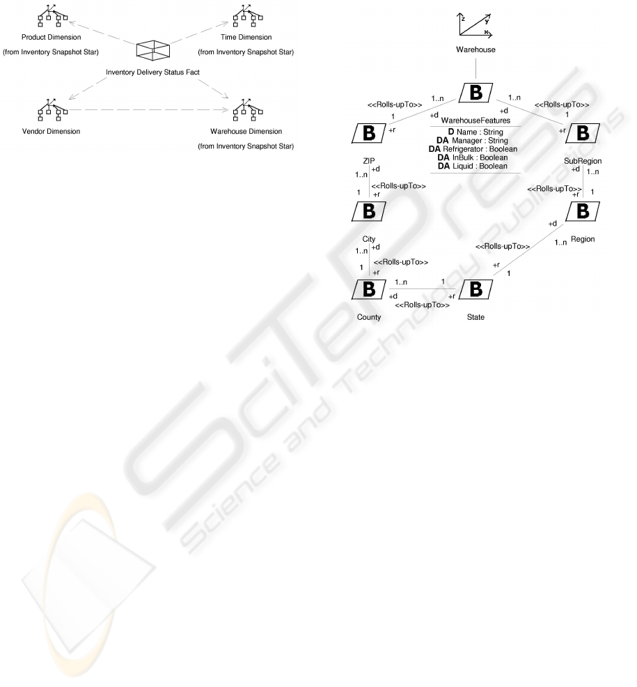
DI ME NS IO NPACKAGEs with the same name but de-
fined in different STA RPACKAG Es. Moreover, a de-
pendency has been drawn from Vendor Dimension
to Warehouse Dimension because both dimensions
share some hierarchy levels, as we will show in the
next section.
Figure 5: Level 2 of Inventory Delivery Status Star.
4.4 Shared Hierarchy Levels
In some cases, two or more dimensions share some
hierarchy levels. As in the case of shared dimen-
sions, the use of the same levels in different dimen-
sions avoids redefinitions and inconsistencies in the
data.
For example, Figure 6 shows the content of the
package Warehouse Dimension (from Figure 4)
and Figure 7 shows the content of Vendor Di-
mension (from Figure 5) at level 3. In a DI-
ME NS IO NPACKAGE, a class is defined for the DI-
ME NS IO N class (Warehouse and Vendor respec-
tively) and one class for every classification hierarchy
level (WarehouseFeatures, ZIP, City, SubRegion,
SubZone, etc.). For the sake of simplicity, only the
attributes of the first BASE class have been depicted
in both diagrams; we can distinguish two kinds of
attributes: DESCRIPTO R, represented by means of a
D icon, and DIMENSIONATTRIBUTE, represented by
means of a DA icon.
In this example, Warehouse and Vendor share
some hierarchy levels: ZIP, City, County, and State.
These levels have been firstly defined in the Ware-
house Dimension; therefore, the name of the pack-
age where they have been previously defined ap-
pears below the class name (from Warehouse Di-
mension) in the Vendor Dimension (see Figure 7).
Moreover, both dimensions contain some hierarchy
levels that do not contain the other: SubRegion and
Region in the Warehouse Dimension, and Sub-
Zone and Zone in the Vendor Dimension.
In this example we also notice a salient feature of
our approach: two dimensions, that share hierarchy
levels, do not need to share the whole hierarchy. The
package mechanism allows us to import only the re-
quired levels, thereby providing a higher level of flex-
ibility. Moreover, we have decided to share a hier-
archy for both dimensions to obtain a clearer design,
although the designer may have decided not to do it if
such sharing is not totally feasible.
Figure 6: Level 3 of Warehouse Dimension.
4.5 Multiple and Alternative
Classification Hierarchies
Defining dimension classification hierarchies is
highly crucial because these classification hierarchies
provide the basis for the subsequent data analysis.
Thanks to the flexibility of UML association relation-
ships, we can represent multiple and alternative clas-
sification hierarchies. On the one hand, a classifica-
tion hierarchy is multiple when a dimension has two
or more classification hierarchies, therefore data can
be rolled-up or drilled-down along two different hier-
archies at least; on the other hand, two or more clas-
sification hierarchies are alternative when they con-
verge into the same hierarchy level.
In Figure 7, Vendor Dimension presents a multi-
ple classification hierarchy: (i) PersonalData, ZIP,
City, County, and State, and (ii) PersonalData,
SubZone, and Zone. On the other hand, Ware-
house Dimension (see Figure 6) presents an alterna-
tive classification hierarchy, because we have defined
two classification hierarchies that converge into State
BA SE class.
ICEIS 2004 - DATABASES AND INFORMATION SYSTEMS INTEGRATION
302
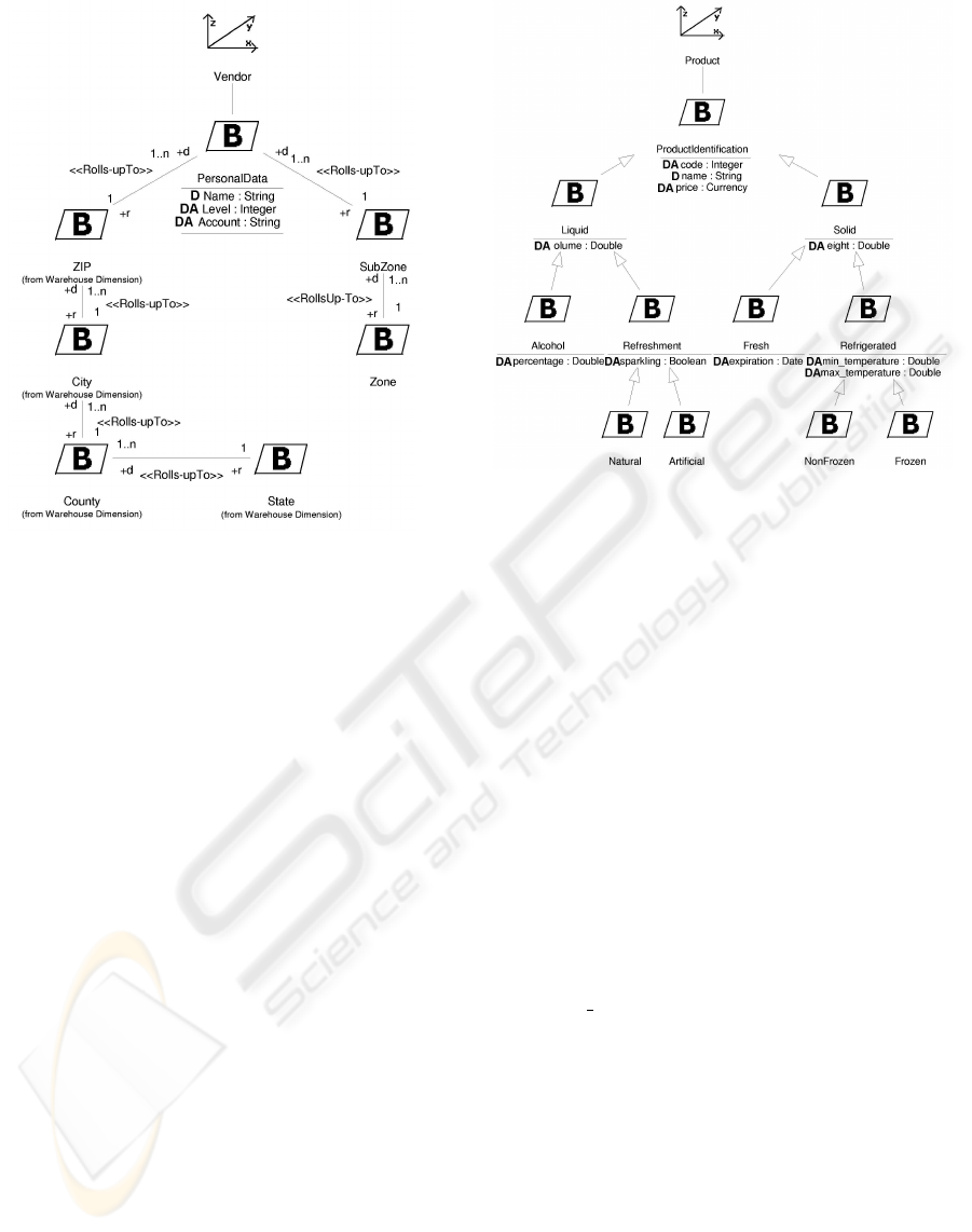
Figure 7: Level 3 of Vendor Dimension.
4.6 Heterogeneous Dimensions
A heterogeneous dimension is a dimension that de-
scribes a large number of heterogeneous items with
different attributes (Kimball, 1996). Our MD mod-
eling approach allows the DW designer to elegantly
represent heterogeneous dimensions by means of
generalization-specialization hierarchies. In our ap-
proach, the different items can be grouped together
in different categorization levels depending on their
properties. In this way, our approach allows us to have
elements at the same aggregation level that have dif-
ferent attributes.
For example, Figure 8 shows the Product Dimen-
sion at level 3. The Product FACT has been modeled
depending on the different subtypes –Liquid or Solid,
Alcohol or Refreshment, etc.–, and each one of
the subtypes contains particular properties –volume,
weight, expiration, etc.–. For the sake of simplicity,
we have omitted sone of the attributes of the BASE
classes.
4.7 Shared Aggregation
In our MD modeling approach, FACT classes are
specified as composite classes in shared aggregation
relationships of n DIM EN SI ON classes. The flexibil-
ity of shared aggregation in the UML allows us to
represent many-to-many relationships between FAC T
classes and particular DIM EN SI ON classes by indicat-
Figure 8: Level 3 of Product Dimension.
ing the 1..n cardinality on the DIMENSION class role.
For example, in Figure 9 we can see how the FAC T
class Inventory Delivery Status has a many-to-
one relationship with the DIMENSION classes Time,
Vendor, Product, and Warehouse (not completely
shown in the diagram). For the sake of simplicity,
we have omitted all the attributes of the DIMENSION
and BASE classes. As noted, there are three shared
aggregation relationships between Inventory Deliv-
ery Status and Time: Ordered, Received, and In-
spected. Thanks to the use of UML named rela-
tionships, we can define more than one relationship
between two classes. In this way, we can use the
same DIMENSION and avoid redundancy and incon-
sistency problems. The FACT class Inventory De-
livery Status contains six FAC TATTRIBUTEs (rep-
resented by means of a FA icon) and two DEGEN-
ER ATEDIMENSIONs (represented by means of a DD
icon). PO number is the key to the purchase order
header record and it is useful to the final user because
it serves as the grouping key for pulling together all
the products ordered on one purchase order (Kimball,
1996).
4.8 Derivation Rules
In the UML, derived attributes are identified by plac-
ing / before the name of the attribute. In our MD mod-
eling approach, the derivation rules are explicitly de-
fined by means of Object Constraint Language (OCL)
(Object Management Group (OMG), 2001) expres-
sions. In this way, we provide a precise and formal
mechanism to define derivation rules.
ADVANTAGES OF UML FOR MULTIDIMENSIONAL MODELING
303
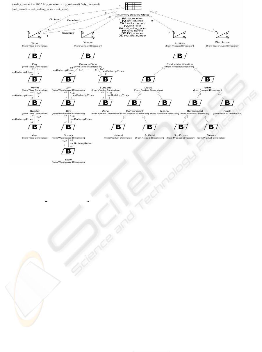
Figure 9: Level 3 of Inventory Delivery Status Fact.
For example, in Figure 9 we can see two deriva-
tion rules for quality percent and unit benefit. The
inclusion of the definition of the derived attributes at
the conceptual design phase avoids the incorrect defi-
nition in the following phases. Moreover, the deriva-
tion rules can be used in a later implementation phase.
4.9 CASE Tool Support
Instead of creating our own CASE (Computer-Aided
Software Engineering) tool, we have chosen to extend
a well-known CASE tool available in the market, such
as Rational Rose 2002. In this way, we do not have to
develop our own CASE tool from scratch.
We have chosen Rational Rose as it is one of the
most well-known visual modeling tools and is ex-
tensible by means of add-ins, which allows the user
to package customizations and automation of several
Rational Rose features through the Rose Extensibil-
ity Interface (REI) (Rational Software Corporation,
2001) into one component. An add-in is a collection
of some combination of the following: main menu
items, shortcut menu items, custom specifications,
properties (UML tagged values), data types, UML
stereotypes, online help, context-sensitive help, and
event handling.
We have developed an add-in, which allows us to
use our MD modeling approach in Rational Rose.
Therefore, we can use this tool to easily accomplish
MD conceptual models
5
. In Figure 10, we can see
a screenshot from Rational Rose that shows the first
level of the inventory example used in Section 4.
Some comments have been added to the screenshot
in order to remark some important elements: the new
toolbar buttons, the new package icons, the new icons
shown in the model browser, and the new menu item
called MD Validate that checks the correctness of a
MD model.
5 CONCLUSIONS AND FUTURE
WORK
In this paper we have presented the main advantages
of our OO conceptual MD modeling approach based
on the UML. We have highlighted the main situa-
tions where the use of the UML means a consider-
able advantage. For example, we have exhibited how
the usage of package diagrams leads to an exception-
ally clean MD design of huge and complex systems,
because package diagrams allow us to structure MD
5
All the MD models shown in this paper have been mod-
eled using our Rational Rose add-in.
ICEIS 2004 - DATABASES AND INFORMATION SYSTEMS INTEGRATION
304
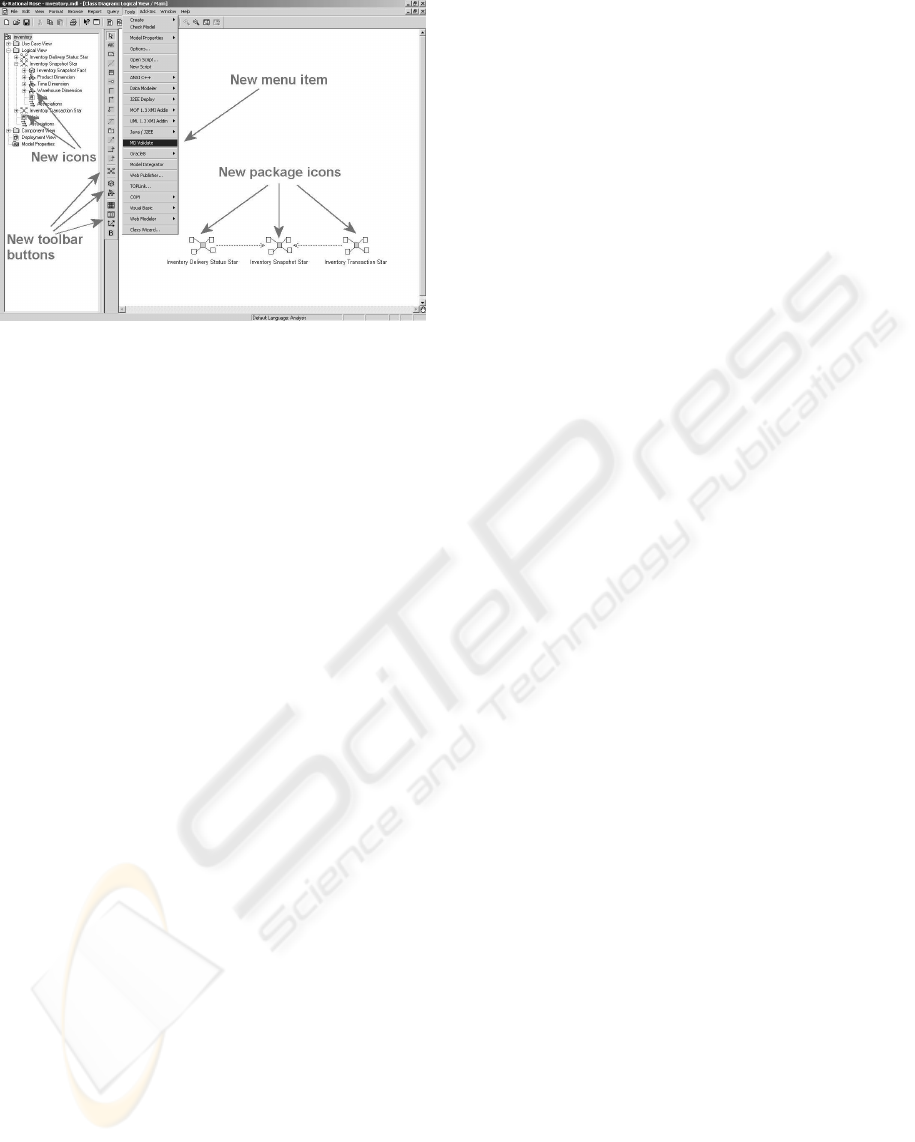
Figure 10: MD modeling in Rational Rose.
models at different levels of abstraction. Moreover,
the importation mechanism in the UML simplifies the
use of an element from one package in another pack-
age. In this way, we avoid the problems related to the
redefinition of an element several times: redundancy,
inconsistency, and ambiguity.
Our MD modeling approach can be continued fol-
lowing several different research lines. Firstly, we are
considering the implementation of the MD concep-
tual models on pure MD databases, object-relational
databases (ORDB), and OO databases (OODB). Due
to the OO nature of our MD conceptual approach,
we are studying the implementation in ORDB and
OODB. Since our MD approach is semantically rich,
we will need to define our own metadata to sup-
port all the expressiveness power of the approach.
Secondly, we also plan to include different imple-
mentation strategies, e.g., the option of normaliz-
ing (snowflake structure) or denormalizing (only one
structure) the dimension hierarchies. Finally, we are
also considering incorporating UML use cases into
our MD conceptual approach. These diagrams will
allow us to partition the functionality of OLAP appli-
cations in an early stage of the analysis phase.
REFERENCES
Abell
´
o, A., Samos, J., and Saltor, F. (2001). A Frame-
work for the Classification and Description of Mul-
tidimensional Data Models. In Proc. of the 12th Intl.
Conf. on Database and Expert Systems Applications
(DEXA’01), volume 2113 of LNCS, pages 668–677,
Munich, Germany. Springer-Verlag.
Blaschka, M., Sapia, C., H
¨
ofling, G., and Dinter, B. (1998).
Finding Your Way Through Multidimensional Mod-
els. In Proc. of the 9th Intl. Workshop on Database
and Expert Systems Applications (DEXA’98), pages
198–203, Vienna, Austria. IEEE Computer Society.
Giovinazzo, W. (2000). Object-Oriented Data Warehouse
Design. Building a star schema. Prentice-Hall, New
Jersey, USA.
Golfarelli, M. and Rizzi, S. (1998). A methodological
Framework for Data Warehouse Design. In Proc.
of the ACM 1st Intl. Workshop on Data Warehous-
ing and OLAP (DOLAP’98), pages 3–9, Washington
D.C., USA.
Kimball, R. (1996). The Data Warehouse Toolkit. John
Wiley & Sons. (Last edition: 2nd edition, John Wiley
& Sons, 2002).
Kimball, R. (1998). Bringing Up Supermarts. DBMS, 11(1).
Luj
´
an-Mora, S., Trujillo, J., and Song, I. (2002a). Extend-
ing UML for Multidimensional Modeling. In Proc.
of the 5th Intl. Conf. on the Unified Modeling Lan-
guage (UML’02), volume 2460 of LNCS, pages 290–
304, Dresden, Germany. Springer-Verlag.
Luj
´
an-Mora, S., Trujillo, J., and Song, I. (2002b). Multi-
dimensional Modeling with UML Package Diagrams.
In Proc. of the 21st Intl. Conf. on Conceptual Model-
ing (ER’02), volume 2503 of LNCS, pages 199–213,
Tampere, Finland. Springer-Verlag.
Object Management Group (OMG) (2001). Unified
Modeling Language Specification 1.4. Internet:
http://www.omg.org/cgi-bin/doc?formal/01-09-67.
Rational Software Corporation (2001). Using the Rose Ex-
tensibility Interface. Rational Software Corporation.
Sapia, C., Blaschka, M., H
¨
ofling, G., and Dinter, B. (1998).
Extending the E/R Model for the Multidimensional
Paradigm. In Proc. of the 1st Intl. Workshop on Data
Warehouse and Data Mining (DWDM’98), volume
1552 of LNCS, pages 105–116, Singapore. Springer-
Verlag.
Trujillo, J., Palomar, M., G
´
omez, J., and Song, I. (2001).
Designing Data Warehouses with OO Conceptual
Models. IEEE Computer, special issue on Data Ware-
houses, 34(12):66–75.
Tryfona, N., Busborg, F., and Christiansen, J. (1999).
starER: A Conceptual Model for Data Warehouse De-
sign. In Pro. of the ACM Second Intl. Workshop on
Data Warehousing and OLAP (DOLAP’99), pages 3–
8, Kansas City, USA. Springer-Verlag.
ADVANTAGES OF UML FOR MULTIDIMENSIONAL MODELING
305
