
COMPONENT-BASED SOFTWARE DEVELOPMENT
ENVIRONMENT (CBDE)
Raphael M. S. Neto, Daniel Lucrédio, Adriano A. Bossonaro, João R. D. D. Cunha, Antonio F. Prado
Computing Department, Federal University of São Carlos, Rd. Washington Luís, Km 235,São Carlos-SP, Brasil
Iolanda C. S. Catarino, Alexandre Marcilio de Souza
Computing Department, UNOPAR – Universidade Norte do Paraná, Rua Tietê, 1208, Londrina-PR, Brasil
Keywords: Component-Based Software Development Environment, Catalysis, EJB and JavaBeans components, CASE
and RAD tool
Abstract: This paper presents an Component-Based Software Development Environment - CBDE that supports the
construction and reuse of software components according to Catalysis. Its integrates a CASE tool, named to
MVCase, and a RAD tool, named to C-CORE, to support the whole process of Component-Based Software
Development (CBD). The CBD process, follows the spiral model of software development, including
activities that start from communication with the customers to identify the requirements for construction and
reuse of components, until the delivery and customers component assessment. This paper focuses on details
related to the two phases of the CBD Construction process. The MVCase and C-CORE help the software
engineer automating great part of the components construction and reuse tasks.
1 INTRODUCTION
In recent years emphasis has been given to the need
for integrated support for software engineering tasks,
that can relate to the software life cycle (Harrison,
2000). At the same time as the integrated software
support development concept was in place, the
principles of Software Development Environment
(SDE) (Moura, 1992) became an important aid in
software development. SDE combines methods,
techniques and tools with this objective in view.
More recently, aided by the software system
composition concept, SDEs have evolved to help in
the development of the Component-Based Software
Development Environment (CBDE). CBDE is an
environment that combines techniques, methods and
tools to support the CBD. The CBDE have possess
an integrated architecture that gives coherency
between the phases of the software development.
Today there are SDEs already available with
resources that greatly facilitate software
development. However, there is still a lack of
integrated environments that support the whole
Development of Software process that are
compatible with the cost involved for the software
industry.
Motivated by these considerations a CBDE was
developed. It uses Catalysis (D’Souza, 1998) as a
mean of component construction and reuse method;
the CASE tool, MVCase for modelling, with UML
techniques; a Rapid Application Development
(RAD) (Pressman, 2001) tool, C-CORE, for
component construction and implementation;
Support for JavaBeans (Sun, 2003) and Enterprise
JavaBeans (EJB) (Sun, 2003) for components
implementation; and Mechanisms to help in the
correction of inconsistencies during the components
and applications development phases.
This paper is organized as follows: section 2
presents the ADSBC environment; section 3
presents the software development process in the
ADSBC; section 4 presents the main mechanisms in
the ADSBC; section 5 presents an actual Case
Study; section 6 presents the conclusions and the
section 7 presents the related works.
2 COMPONENT-BASED
SOFTWARE DEVELOPMENT
ENVIRONMENT (CBDE)
The CBDE is a computer system that provides
support for development, repair and improvements
338
M. S. Neto R., Lucrédio D., A. Bossonaro A., R. D. D. Cunha J., F. Prado A., C. S. Catarino I. and Marcilio de Souza A. (2004).
COMPONENT-BASED SOFTWARE DEVELOPMENT ENVIRONMENT (CBDE).
In Proceedings of the Sixth International Conference on Enterprise Information Systems, pages 338-343
DOI: 10.5220/0002638303380343
Copyright
c
SciTePress
of components and of their applications
The main characteristics presented by the
proposed CBDE are: Mechanisms that support the
construction and reuse of components; Module
responsible for controlling the access and objects
evolution, known as the environment Repository;
Support for the inclusion of new tools to allow the
extension of the environment through an efficient
integration mechanism within the environment; and,
Integration between all modules. The environment
tools agree on the types of data, operations, methods
utilized and the developmental process being
followed. Being integrated, the tools share
information consequently, avoiding redundancies
and inconsistencies.
The CBDE tools are integrated through
mechanisms of: Presentation: The interfacing of the
CBDE tools are built based on the same user
interface library denominated Motif (Sun, 2003);
Control: The tools influence others, that is, they
share functions, activate other tools and inform each
other of up-coming activities; and Integration: data
integration is obtained by means of sharing the same
data and interpretation between the tools. The
sharing operation is established through XMI
extension files (XMI, 2003).
The CDBE integrates two tools. The integration
constitutes one of the great advantages of developing
components and their applications. Besides the
support in the different phases of the development is
also had the support among the development phases.
Modelling flaws, inconsistencies that occur during
the software development phases can be auto-
matically corrected by the environment mechanisms.
A component or application can be refined and
validated by means of an execution environment,
permiting the detection and correction of possible
flaws, defore it is released to the consumer.
CBDE also provides a software development
process that consists of a group of tasks enabling
software construction. Next is a process description.
3 SOFTWARE DEVELOPMENT
PROCESS WITH CBDE
SUPPORT
The proposed CBDE follows the Component-Based
Development (Pressman, 2001). This model can be
considered an evolution from the spiral model. The
spiral model (Pressman, 2001) is an evolutionary
model for the software development, incrementally
generating prototypes based on a sequence of
operations. CBDE follows the spiral model, adding
tasks that take into consideration the construction
and reuse of components. Each stage of the life
cycle is accomplished by a group of work tasks that
are adapted to the characteristics of the project being
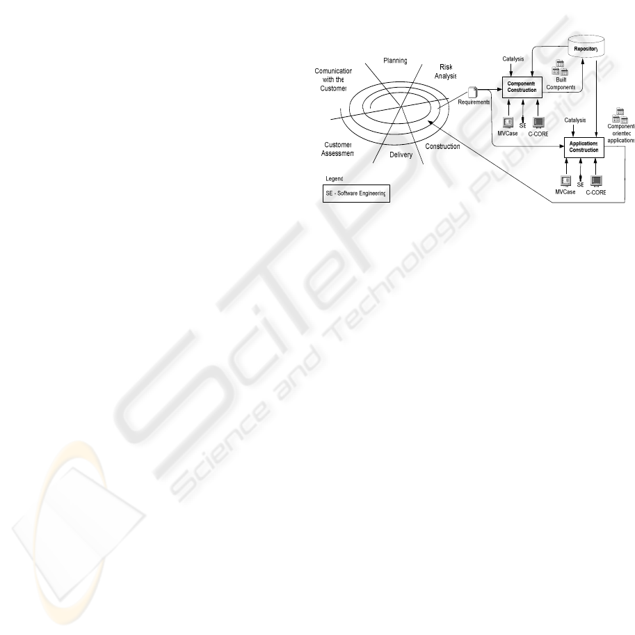
developed.The Figure 01, adapted from (Pressman,
2001), shows on the left, the model of the
Component-Based Development process withing the
proposed environment, divided in 6 stages:
Communication with the Customer; Planning; Risk
analysis; Construction; Delivery; and Customer
Assessment. The process is evolutionary and to each
cycle a new prototype is added. To the right of
Figure 01, there is, in SADT
1
notation (Ross, 1997),
a more detailed view of the Construction stage, that
is divided in 2 phases: component and application
construction
Figure 01 - CDB model
Next we describe the process stages. The
construction stage is presented with more details,
with a greater emphasis on production and reuse of
components.
3.1 Comunication with the customer,
Planning and Risk Analysis
At the Communication with the customer stage,
steps are taken to establish communication between
the software engineer and the customer. Different
techniques are used, for example, meetings,
questionnaires and others that may be used to
identify the requirements of the problem domain.
In the Planning stage, tasks related to the
planning of Project resources and time limits are
undertaken. To this end, initially, a description of the
scope of the Project is broken down into smaller
units wich allow estimate, utilizing historical and
experiential data, of time and resources needed
In the Risk Analysis stage, technical and
managerial risks are evaluated. The risks constitute
uncertainties in estimates, cronogram, resource and
others. The identification and analysis of risks helps
understand and administer uncertainties. Each
identified risk is analyzed and later classified by
probability and impact. Finally a plan is elaborated
to administer the risk(s). Also the viability of
development of the actual software is analyzed. Next
to this the component development phase and
COMPONENT-BASED SOFTWARE DEVELOPMENT ENVIRONMENT (CBDE)
339

application construction is iniciated.
3.2 Construction
At this stage components and applications are
developed in 2 phases, the Component Construction
and Application Construction. In the first phase,
domain components that are not present in the
repository are developed, starting from
understanding the Problem Domain. Components
implemented, in a component-oriented language are
stored in a repository, for instance, components of
basic domains can be like GUI and DB, can be
found in domain applications such as E-Learning, E-
Commerce, and others. In this phase, components of
a Problem Domain are built in five steps: Problem
Domain, Component Specification, Component
Internal Project, Specific Component Construction
Application and Component Implementation. The
EJB architecture is used to Project and to Implement
the components.
In the Problem Domain step, the requirements of
the domain are specified using Catalysis techniques.
Then, the specifications at the Problem Domain
level are refined to obtain new specifications now
component-oriented. The next step continues the
process of refinement of the component
specifications, at this point considering the platform
and the architecture adopted for the project. In the
event that Java is the programming language and
EJB the component project technology.
Having built the components of the problem
domain, the Software Engineer can build
applications that reuse the components in the
Application Construction phases. This begins with
application requirements and takes into account the
software’s expected life-cycle that includes,
Specification, Project and Implementation of the
Application. In the Application Tests step, the
Software Engineer tests the application to verify
whether or not the application meets with the
specified requirements. The Catalysis method and
the MVCase and C-CORE tools are also used here to
orient and to support the development process.
Tests allow the verification as to whether or not
the components meet the requirements of the
applications domain. This model mainly seeks
software reuse allowing the benefits of reduced
development time, costs, besides increasing the
compatibility of the developed software. The
following activities deal with the delivery and
assessment of the development process at each stage
ot the components life cycle.
3.3 Delivery and Customer
Assessment
The tasks in the Delivery stage are designed to
install and to supply support to the user in, for
instance, documentation and training (Pressman,
2001) and the tasks in the Customer Assessment
stage are necessary to obtain the customer feedback,
through an assessment of the software during the
development and implementation stages and during
the application installation (Pressman, 2001).
The CBDE tools are used to help some process
stages. Next we present the tools available in the
CBDE to help the Software Engineer.
4 MAIN MECHANISMS: C-CORE
AND MVCASE TOOL
The C-CORE is a tool centered in the Java
programming language, which supports the
development and reuse of software components. It
has graphic and textual interfaces that facilitate
CBD. It was developed according to the Catalysis
component-based development method, with the
Java programming languages and XML (XML,
2003). Its graphic interface was built using
Java/Swing libraries of the package. The
components are built according to the Java Beans
architecture, and they use reflexive classes (Sun,
2003), to support introspection. The introspection
analyses the code object of the component and
passes to the tool properties that indicate the
component’s presentation and state including the
events generated so that the Software Engineer can
define what actions to be taken as a result of their
occurrence. The editing of the properties values and
of the actions of the events supported.
The MVCASE (MVCase, 2003) is a Java-based,
platform-independent modelling tool, providing
graphical and textual techniques based on UML
notation (Booch, 1999).
By supporting UML, MVCASE allows the
Software Engineer to specify systems in different
abstraction levels and in four different views: Use
Case View, Logical View, Component View and
Deployment View.
To persist with the UML specifications,
MVCASE uses the OMG’s XMI format (XML
Metadata Interchange) standard. The XMI is a
XML-based format used to represent UML models.
Based on four views cited above, MVCASE
generates XMI descriptions that can be physically
stored, in a file or a repository.
ICEIS 2004 - INFORMATION SYSTEMS ANALYSIS AND SPECIFICATION
340

5 CASE STUDY
To test CBDE was build a framework for E-
Learning (EL) with 60 software components. It was
a result of a master degree dissertation (Sanches,
2002). The framework supports the elaboration and
the administration of courses, assisting, mainly,
requirements related to the resources and didactic
services, administrative and course support. The
main customers involved in the EL domain of this
case study are specifically teachers and the students.
The following is a presentation of each step in the
development and reuse process according to that
indicated in section 3.
5.1 Comunication with the Customer,
Planning and Risk Analysis
Initially "brainStorming" sessions were
accomplished, involving teachers and students with
the intention of specifying the context of the
problem and to identify the requirements related to
the different applications of E-Learning domain
using it as a problem domain. As a result of these
sessions a group of documents and models that
described the identified requirements was
elaborated. Starting from the identified
requirements, hardware and software necessary for
task accomplishment were determined. Developers
were allocated to work on the required tasks. For
this a cronogram was defined for these activities and
the costs for the accomplishment were also dear.
Starting from the cronogram and of the dearly
costs, were identified the risks that the project was
exposed. A systematic assessment was
accomplished, mapping the threats and
vulnerabilities in his viability. They were also
prioritized actions to subsidize effective alternatives
for the uncertainties.
5.2 Construction
In this phase, Component Construction, the E-
Learning domain components were built. In the
Problem Domain step, corresponding to the first
level of Catalysis, the requirements and the rules of
business of the EL domain are identified. The
requirements were obtained starting from the study
of several courses authorship environment: WebCT
(Sanches, 2002), AulaNet(Sanches, 2002) and
LearningSpace (Sanches, 2002). In this step are
identified also the actors, and their interactions in the
context of the EL domain. The following actors were
identified: Administrator, Author, Teacher and
Student. Different models built in this development
stage as a mind-map (D’Souza, 1998) had with the
identified actors, which creates the collaboration
model, that is represented in a cases of use model,
that it represents the actors and their interactions in
the content of the problem domain, in which
represents the case of use to register for each actor.
In the Component Specification step,
corresponding to the second level of Catalysis, the
Problem Domain models are refined, being specified
the Types (D’Souza, 1998) and Sequence (Fowler,
1997), (Booch, 1999) Models, without worrying
with the implementation. The model of types is
obtained by the refinement of the use case models,
that represent the behaviors of the objects and their
messages connections, and of the snapshot models
that represent the attributes of the objects and their
relationships. The Use Case Models, of the previous
step, are refined in Interactions Models represented
by the sequence diagrams, aiming to detail the
sceneries of use of the components in the different
applications of the problem domain.
In the Component Internal Project step,
corresponding to the third level of Catalysis, the
classes are modeled, obtained by the refinement of
the types of the domain built in the second step,
worrying about the definition of the components
with their interfaces. Now, the implementation
details are important, such as: safety, persistence,
distribution architecture and the implementation
language. The Interactions Models are refined to
show project details of the methods behaviors in
each class. In the Specific Component Construction
Application step, the software engineer consults in
the repository all the components that he needs to
build. With the identification of the components that
are already available for the reuse, the Software
Engineer can refine the components model reusing
these available components. The specific
components of the application that are not in the
repository are built aiming to complete the
application.
In the Component Implementation step, the
Software Engineer uses MVCase to accomplish the
implementation of the components in the EJB
architecture. After having built the components of
the problem domain, the Software Engineer goes to
the Application Construction.
Different applications of the problem domain can
be developed reusing the EL components framework
built. Figure 02 summarizes one of the applications,
of this domain.
COMPONENT-BASED SOFTWARE DEVELOPMENT ENVIRONMENT (CBDE)
341
It is an application that supports the development
of courses to teach HTML, Flash and others. The
application has an interactive interface that makes
possible that interested people can register in one or
more courses than are periodically offered. A course
has a responsible, the course author, and one or more
teachers that watch the course. All of the classes of a
healthy course registered by the date and schedule.
A student's registration is approved or not by the
application administrator, after the approval of the
student's personal register. The application should
control the type of permission of the users' access:
administrator, author, teacher, and student. The
application still controls the assessment and
exercises of the courses.
Figure 02 – E-Learning Application
In the Application Specification step, the problem
understanding is accomplish with the application
requirements identification. Before beginning the
application requirements specification, in the
MVCase, the Software Engineer imports the
problem domain components, in this case E-
Learning components, that will be reused by the
application. Another model built in this stage is the
Use Cases Techniques, like Mind-Maps, SnapShots
(D’Souza, 1998) and others.
Afterwards, the models previously specified are
refined, reusing the framework components.
In the Application Project step is made the
component internal project of the application. The
classes model is obtained by the refinement of the
types model specified in the previous step.
In the Application Implementation step is made
the implementation of the application with base in
his project. A first version of the implementation is
generated in the MVCase, starting from the class and
components models. Afterwards, the implementation
continues in the C-CORE, that has resources to
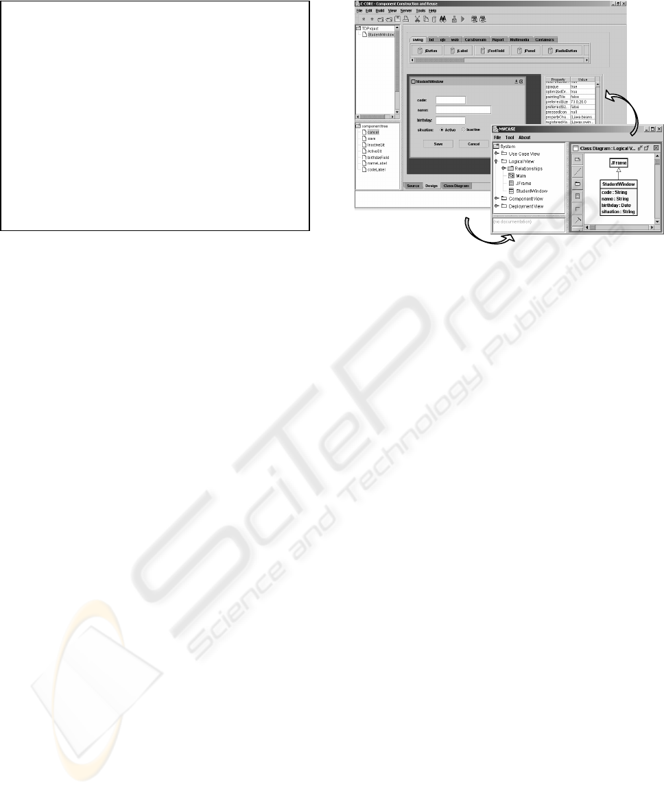
refine the code. Figure 03 shows the development of
the Student interface of the application in the C-
CORE tool, reusing component from GUI domain.
For each component selected in the application, C-
CORE generates your respective code. The Object
Inspector allows the direct interaction in the
properties and events of the components selected
that can be altered in "design" and execution time
through method calls. The Software Engineer can
develop the project in the C-CORE, and through the
interaction with MVCase can obtain the consistence
modelling of the application
In the Application Tests step, the Software
Engineer accomplishes tests with the application.
The tests, allow verifying if the application satisfies
the specified requirements. The results of execution
can guide the Software Engineer in the debugging
process of the application and of the components of
the built domain.
Figure 03 – Development of the Student Interface
5.3 Delivery and Customer
Assessment
In the Delivery stage, were deliver the produced
artefact, jointly with the hardware configuration and
software, that allowed do the deployment of the
components distributed in different computers.
Afterwards, trainings were accomplished with the
users, jointly with the documentation of the built
application.
In the Customer Assessment stage, assessments
of the artefacts were accomplished. Were detected
some problems which were corrected through tasks
of the maintenance. Besides that, were observed on
the part of the customer some details related to new
requirements that were not initially identified.
Therefore, this stage contributed to the stage of
communication with the customer of the next
iteration of the cycle of life of the components and
their applications. About the planning of the
accomplished project, it was made an assessment of
the accomplished activities as the productivity, real
costs verse forecast costs and periods.
6 CONCLUSION
This paper presented a Component-Based Software
Development Environment (CBDE), that supports
the construction and reusing components method.
The CBDE integrates a CASE tool with focus for the
modelling and a RAD development tool with focus
for the implementation to support the component-
based software development process.
The environment architecture allows the tools to
cooperate amongst themselves allowing to minimize
the periods and costs of the software development.
Integration with MVCase
Integration
with
C-CORE
ICEIS 2004 - INFORMATION SYSTEMS ANALYSIS AND SPECIFICATION
342

Between the advantages of the environment can
emphasize the CBD support. The use of components
allows the maintenance of the simplest and reliable
software, once the components are blocks that were
previously tested. And, other advantages of the
environment are: the support to the Catalysis method
for the components and applications development,
the support for the phases and during the phases of
components and applications development,
facilitating the corrections of the inconsistencies,
and the generation of great part of the code starting
from the specifications in high abstraction level.
7 RELATED WORKS
Aiming to help in the process of software
development there are integrated tools as, for
instance, Poseidon (Poseidon, 2003) and NetBeans
(NetBeans, 2003) and others. Poseidon is a
modelling tool, that is a commercial version of the
ArgoUML (ArgoUML, 2003) that contains
functionalities and additional innovations. Some
versions have additional resources as, for instance,
RoundTrip that allows modelling of classes from the
source code and vice-versa, UMLDoc that produces
documents in HTML, JarImport that generates a
classes model and your relationship starting from a
jar file and MDLImport that allows importing from a
MDL project. NetBeans is an application
development environment (IDE) free, oriented for
Java language and it allows the fast development of
applications with GUI. It has resources for
compilation and debugging of the Java code,
wizards that allow creating different types of Java
applications quickly as, for instance, RMI (Sun,
2003), applets (Sun, 2003), JavaBeans and others
Poseidon is a stable and complete tool. However,
it is not free. NetBeans is equally complete, is free
but it is used only for Java. The use of integrated of
theses tools should be accomplished with the use of
appropriate versions.
The CBDE presents tools destined to the
modelling and implementation too. However, such
tools are of open code, they presents the RoundTrip
and MDLImport resources, the possibility of
extension of functionalities, because both are open
code and it presents support for component
construction and reuse in differents architectures.
ACKNOWLEDGMENT
The authors would like to thank to CAPES, FAPESP
and UNOPAR, the brazilian institutions which help
to support this work.
REFERENCES
Pressman, R., S, 2001; Software Engineering: A
Practitioner's Approach. McGraw-Hill.
Rational Software; Rational Rose Tool. URL:
http://www.rational.com. Consulted in 03/12/2002.
MVCase Tool Site, URL: http://www.recope.dc.ufscar.br/
mvcase consulted in 30/09/2003
Booch, G. et al.; The Unified Modeling Language – User
Guide. USA: Addison Wesley, 1999.
Ross, D. T.; Structure Analysis (SA): A language for
communicating Ideas. IEEE Transaction on Software
Engineering. 1997
Harrison, W., Ossher, H., Tarr, P., 2000, “Software
Engineering Tools and Environments: a Roadmap”,
In: Proceedings of The Future of Software
Engineering, 22nd. ICSE 2000
Moura, L. M. V., Rocha, A. R. C., 1992, Ambientes de
Desenvolvimento de Software, Publicações Técnicas
COPPE/UFRJ, ES-27/01/92, Rio de Janeiro, Brasil.
D’Souza, D.; Wills, A; 1998. Objects, Components and
Frameworks with UML – the Catalysis Approach.
Addison Wesley, USA.
Fowler, M.; 1997. UML Destilled - Applying the Standard
Object Modeling Language. Addison Wesley, England.
Sun Microsystems; Java Language. URL:
http://java.sun.com, Consulted in 14/03/2003
XML. Extensible Markup Language (XML) URL:
http://www.w3.org/XML. Consulted in 14/04/2003.
The Common Object Request Broker - CORBA. URL:
http://www.omg.org. Consulted em 14/03/2003
Sanches, I.C.;2002. Framework para Ensino a Distancia
via Web. Mastes degree dissertation – PPG in
Computer Science – Computing Department –
UFSCar, São Carlos, São Paulo – Brasil.
Object Management Group. XML Metadata Interchange
(XMI) – Version 1.2. Available at Site OMG. URL:
http://www.omg.org/technology/documents/formal/xm
i.htm - Consulted in February, 2003.
Poseidon Site, URL: http://www.gentleware.com,
consulted in 30/09/2003
NetBeans Site, URL: http://www.netbeans.org, consulted
in 20/09/2003
ArgoUML Site, URL: http://argouml.tigris.org/, consulted
in 30/05/2003
COMPONENT-BASED SOFTWARE DEVELOPMENT ENVIRONMENT (CBDE)
343
