
REAL-TIME DATABASES FOR SENSOR NETWORKS
Pedro Fernandes R. Neto
Departamento de Inform
´
atica, Universidade do Estado do Rio Grande do Norte(UERN), Mossor
´
o, RN
Maria L. B. Perkusich
Departamento de Inform
´
atica e Estat
´
ıstica, Universidade Cat
´
olica de Pernambuco, Recife, PE
Angelo Perkusich
Departamento de Engenharia El
´
etrica, Universidade Federal de Campina Grande,
Campina Grande, PB, Caixa Postal 10105 - CEP 58109-970
Keywords:
Real-Time Databases, Petri Nets, Embedded Systems, Sensor Networks.
Abstract:
In the last years, the demand of embedded systems has been increased. Also, due to the increasing compe-
tition among different kind of companies, such as cellular phone, automobiles and industrial automation, the
requirements for such systems are getting more complex. However, the data storage and processing tech-
niques, for these environments, are insufficient for the new requirements. In this paper, we develop a model
for the integration of real-time database technology with an embedded sensor network systems, to tackle such
deficiencies. Coloured Petri nets are the mathematical framework used for the modelling and analysis.
1 INTRODUCTION
In the last years, the demand of embedded systems
has been increased. Also, due to the increasing com-
petition among different kind of companies, such as
cellular phone, automobiles and industrial automa-
tion, the requirements for such systems are getting
more complex. Each one of them aggregate more
functionalities to embedded devices, as well as dif-
ferent processing capabilities for the products. How-
ever, one of the main problems to deal with due to
the increase in the functionalities and complexity of
these systems, results in an increase of the amount
of the data. Such data must be efficiently man-
aged and stored considering specific non-functional
requirements of the application, such as, for example,
size and power consumption.
Nevertheless, the techniques that exist for process-
ing and data storage in embedded devices are limited
and, therefore, they are insufficient in face of the new
requirements of the applications. Aiming at assisting
such limitations, some commercial databases man-
agement systems (DBMS) already are being adapted
for embedded environments. However, as pointed
out in (Tesanovic et al., 2002), the a commercial
DBMS (i) does not execute normally in embedded op-
erational systems, (ii) does not support the database
properties (ACID: Atomicity, Consistency, Isolation
and Durability), (iii) do not minimize the system
resources use, and (iv) do not assure time require-
ments. So, it can be impracticable to use conventional
databases in embedded systems due to the particular
requirements of such systems.
Another observation about the correctness of these
systems is that while the correctness in the database
depends on the logical consistency of the data and
the transactions, for embedded systems the correct-
ness depends, also, on timing constraints. Due to the
need of timing constraints real-time database systems
(RTDB) can be applied in the context of embedded
systems, in order to satisfy them (Tesanovic et al.,
2002; Hansson, 2002).
In the context of this paper we consider sensor
networks as the embedded system case study. In
most cases, such sensor networks are build using
preprogrammed devices that send data for a central
database, where the data is stored for off-line analy-
sis and queries (Chen et al., 2001). This approach has
some limitations, such as communication overhead,
and power consumption in the case of wireless sensor
networks. In (Chen et al., 2001; Bonnet and Seshadri,
2000) it is considered a new architecture, where the
environment can be seen as a distributed database sys-
tem, formed by a server database and each component
is a local database.
However, still exist many subjects to be investi-
gated in this context. In this paper, we develop a
model for the integration of real-time database tech-
nology with an embedded sensor network systems.
Coloured Petri nets are the mathematical framework
used for the modelling and analysis (Jensen, 1997).
Also, we used a set of computational tools for editing
599
Fernandes R. Neto P., L. B. Perkusich M. and Perkusich A. (2004).
REAL-TIME DATABASES FOR SENSOR NETWORKS.
In Proceedings of the Sixth International Conference on Enterprise Information Systems, pages 599-603
DOI: 10.5220/0002644505990603
Copyright
c
SciTePress

and analyzing CPNs named Design/CPN (Jensen and
al, 1999). We have used the resulting model consid-
ering logical and timing constraints for both data and
transactions.
This paper is organized as follow: in Section 2 we
describe the sensor networks and its limitations due to
the existing approach. We show, also, characteristics
of the new architecture, to (Chen et al., 2001; Bonnet
and Seshadri, 2000), for these networks. In Section 3,
we detail the modelling for a real-time database appli-
cation for the sensor network. In Section 4 we show
the model analysis. Finally, in Section 5 conclusions
are presented.
2 SENSOR NETWORKS
The modern sensors are capable of storing and pro-
cessing local data, as well as transferring these data.
Thus, the processing can be made in the sensor net-
work, reducing the use of energy and the data traf-
fic and, consequently, increasing the network life time
(Bonnet et al., 2000).
A sensor network consists on a great device num-
ber connected through communication interfaces that
can be communicated between itself through network
protocols. Each sensor have limited capacity of stor-
age and processing, or either, a sensor has a purpose-
general CPU to process and storage small space to
save programs code and data.
The sensors are not always fixed in an infrastruc-
ture, being power through batteries, making the en-
ergy economy an important task. The communication
consumes much more energy than processing, becom-
ing attractive to reduce the amount of the data flow
between knots by local processing. One another con-
sideration in sensor networks is that knots can inhabit
in hostile environments, what requires a robust sys-
tem for the fast recovery case happens imperfections
(Bonnet and Seshadri, 2000; Bonnet et al., 2000).
The sensors transactions possess time labels. Its
values must be frequently update, since sensors data
become invalid due to the timing constraints. Long-
running query, that periodically recomputation the
sensors transactions results, are a possibility to keep
these update results.
In sensor network, users typically ask three kinds
of queries, (Bonnet and Seshadri, 2000): Histori-
cal queries: these are typically aggregate queries
over historical data obtained from the device net-
work. Snapshot queries: these queries concern the
device network at a given point in time. Long-running
queries: these queries concern the device network
over a time interval.
The warehousing approach represents the state of
the art (Bonnet et al., 2000). The queries processing
on the extracted data of the sensors and the access to
the network are two distinct stages. The sensor net-
work is simply used to collect data. The query mech-
anism proceeds in two steps. First, the data are ex-
tracted of the devices of a form predefined and stored
in a database server. Second, the queries process-
ing are accomplished in the server. This approach
is appropriate to answer query predefined on histor-
ical data. Some disadvantages are visible, such as:
(1) waste of valuable resources for transferring great
amounts of data for the server, where many of these
data are irrelevant and (2) it is not appropriate to an-
swer snapshot and long-running queries.
Considering the disadvantages mentioned in the
warehousing approach and the increase of the sup-
ported functionalities for the sensor, a new approach
is being proposed for these networks. Called ap-
proach distributed (Bonnet and Seshadri, 2000), this
allows that some queries can be processed in the own
device and, also, that the database system to control
the resources that are used. It is primarily targeted
at snapshot and long-running queries; in addition ag-
gregate queries over historical data could be evaluated
against materialized data stored on some devices in-
stead of a centralized server (Bonnet et al., 2000). In
our work, we adopt this approach.
3 RTDB MODEL FOR SENSOR
NETWORKS
In this Section, we describe a model in Coloured Petri
nets of real-time database for sensor network. For
the modelling we use the coloured Petri nets (CPN)
(Jensen, 1997) due to the fact that they offer an envi-
ronment uniform for modelling, formal analysis and
simulation of discrete events systems, allowing to a
simultaneous visualization of its structure and behav-
ior.
In the model, we consider two sensors, two up-
date transactions, a query transaction and a server
database object. The sensors acquire the data of the
environment, store and transmit the data for the server
database object. This consequently reduce the data
flow in the network and the energy waste. The server
is updated in order to allow that historical query are
accomplished, a time that is not possible to store all
the data in the sensor for a long period of time. Is
important to observe that the sensor data are always
more current than the server data. This difference
happens due to the delay that exists between an ac-
quisition of the data, for the sensor, and the update of
this data in the server.
We show the components that form the model. We
illustrate each one, considering the notation of Petri
nets, where the states (places) are represented by cir-
ICEIS 2004 - DATABASES AND INFORMATION SYSTEMS INTEGRATION
600
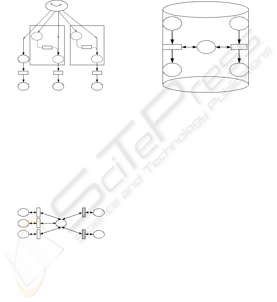
cles and events (transitions) by rectangles. These are
connected by arcs.
The sensor component has a place that acquires the
data (place A) and other to store them (place B). The
action of storing is represented by the rectangle shown
in Figura 1.
A
B
Acquires data of
the real world
Stores data
A’
B’
Acquires data of
the real world
Stores data
C C’
B'’
C'’
Query
Update 1 Update 2
Sensor 1 Sensor 2
Figure 1: CPN Clock Component with Transactions
The transactions and the sensors are synchronized
by a global clock, that establishes the time of the sys-
tem. The transactions and the sensors possess timing
constraints. The Figure 1 illustrates the transactions
with two places and a transition. The behavior is as
follow: the place A and A
0
acquires the data. Then
these data are stored in places B e B
0
. Periodically the
update transactions are executed, in order to keep the
server with the current data acquired by the sensors.
The query transaction, also periodically, can accom-
plish historical query in the server, as well as snapshot
and long-running queries directly in the sensors.
ID
C’
C
C'’
D
D’
Update
Query
Query
Update 2
Update 1
Figure 2: CPN Network Component
Figure 2 shows the model of network, or either, the
way as the transactions to have access to the server.
The transactions are represented by the places C, C
0
e
C
00
. The place ID verifies if it is an update or a query
transaction and the places D and D
0
are the places
that will have access to the database object update
or query, respectively. In the network has an inter-
mediate layer that guarantees the serializability prop-
erty during the concurrent execution of the conflicting
transactions. In this layer, illustrated by the rectan-
gular shadings in Figure 2, we model the negotiation
function.
It is important to observe that the model state for
the negotiation function alone is modified if the at-
tempt of concurrent execution of two distinct transac-
tions, where they are trying to have access the same
data item and at least one of them is of update.
D’
Query
DC’
BD
D
Update
DA’
Server Database
UpdateQuery
Figure 3: CPN Server Database Component
Finally, we have the referring component to the
server database object, Figure 3. This possesses two
methods, update and query. The places D and D
0
are the same places that the represented in the Fig-
ure that illustrates the network. In the nomenclature
of Petri nets, when a place is identical the another, in
an another page, is called of fusion place. A query
or update executed in the database, place BD, the re-
sult will be placed in the places DC
0
and DA, re-
spectively. These places also are fusion places of the
places D and D
0
, Figure 2.
4 MODEL ANALYSIS
For analysis purposes we consider a situation where
the updates and the queries are trying to access the
same data item in the database server application. We
perform both logical and timing verification for the
data and transactions. Thus, we analyze the trans-
actions scheduling, considering the semantic concur-
rency control, where the correctness criterion is the
epsilon serializability considering quality of service.
To analyze the model we consider a situation where
two sensors acquire data of the same type. Sensor1:
writes periodically in the local database, and the re-
lease time is 1 time unit (t.u.) and the period is 6 t.u..
We consider that the value of the data item may vary
between 8 and 11 units. Sensor2: writes periodically
in the local database, and the release time is 9 t.u. and
the period is 9 t.u.. The value of the data item may
vary between 8 and 11 units. Update 1: periodically
REAL-TIME DATABASES FOR SENSOR NETWORKS
601
updates the server database object with respect to the
data in Sensor1. The release time is 3 t.u., the com-
putational time is 2 t.u., the deadline is 12 t.u. and the
period is 12 t.u.. Update 2: periodically updates the
server database object for sensor2. The release time
is 9 t.u., the computational time is 4 t.u., the deadline
is 18 t.u. and the period is 18 t.u.. Query: periodically
queries the real time server database application. The
release time is 3 t.u., the computational time is 6 t.u.,
the deadline is 12 u.t. and the period is 12 t.u..
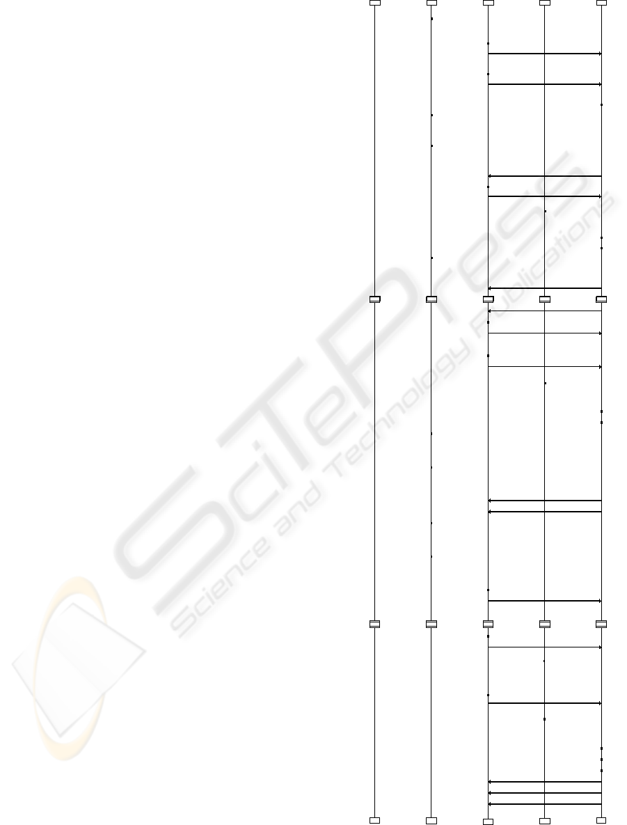
In Figure 4, we present the message sequence dia-
grams for both the execution of transactions and sen-
sors. The Figure illustrates the execution of transac-
tions, as well as the updates in the server database.
It is also possible to observe the time properties for
each component and when the compatibility function
is evaluated due to the transactions concurrent execu-
tion. Each arrow represents the transaction execution.
In the time instant 1 a writing in Sensor1 occurred,
as indicated in the line labelled by Sensor Database.
Each execution is identified by the label Write Oper-
ation Sensor1 and the value added. In the line la-
belled Time Propr. time properties for both sensors
and transactions can be observed. Considering the
quality of service management functions as detailed
in (RibeiroNeto et al., 2003), this line represents the
specification and monitoring functions. The first ex-
ecution for Sensor2 is in 9 t.u., as seen in the Figure
4.
In time 3, Query and Update 1 transactions start.
As observed in the arrows labels, two conflicting op-
erations will try to access a data record in the Server
Database. The first is a query and the second an up-
date (to update the data item t1 to 8).
The transaction Query commits in time 9. The
transaction Update 1 had to wait the query and then
access the server. This can be observed by observ-
ing its computational time, where the committing oc-
curred in time instant 13, that should to be in time
instant 7. Thus, the operations could not be con-
currently executed, or either, the negotiation function
(compatibility function) was evaluated to false.
Before the transaction Update 1 commits, transac-
tion Update 2 begins execution. One more time, con-
flicting operations try to have access to the server at
the same time. However, for this concurrent execu-
tion, the negotiation function was evaluated to true.
The evaluated parameters can be seen in the Figure 4.
The line Negotiation with a label with CF evaluate fol-
lowed by the parameters and its respective execution
time values. Thus, transaction Update 2 can execute
concurrently.
Time Propr Sensor Database
Write Operation Sensor1
1
Write Operation Sensor1
7
Write Operation Sensor2
9
Write Operation Sensor1
13
Transactions
Query
3
Update 1
3
Update 2
9
Negotiation
CF Evaluate
9
Server Database
Read Operation Server
9
Write Operation Server
Write Operation Server
13
Value = 8
Sensor1[tl=1,pe=6]
Read data item t1 in the server
Up1[tl=3,tc=4,pr=12,pe=12]
Write value [8] for t1
Quer[tl=3,tc=6,pr=12,pe=12]
Value = 11
Sensor1[tl=7,pe=6]
Value = 8
Sensor2[tl=9,pe=9]
Item value t1 read in the server [0]
Write value [8] for t1
Up2[tl=9,tc=4,,pr=12,pe=12]
(New value=[8]-Current value=[8])
<=(Exp_max_Col=[10]-Exp_imp=[0])
Value = 10
Sensor1[tl=13,pe=6]
UpdateOk
Write Operation Sensor2
18
Write Operation Sensor1
19
Write Operation Sensor1
25
Write Operation Sensor2
27
Update 1
15
Query
15
Update 2
27
CF Evaluate
15
13
Write Operation Server
Read Operation Server
19
21
UpdateOk
Write value [10] for t1
Quer[tl=15,tc=6,pr=12,pe=12]
Read item data t1 in the server
Up1[tl=15,tc=4,pr=12,pe=12]
[t1],Transaction Status=null
(VrUp=[10]-VrS=[8])<=(CI=[7]-II=[0])
Value = 10
Sensor2[tl=18,pe=9]
Value = 8
Sensor1[tl=19,pe=6]
UpdateOk
Item value t1 read in the server is [8]
Value = 10
Sensor1[tl=25,pe=6]
Value = 10
Sensor2[tl=27,pe=9]
Write value [10] for t1
Up2[tl=27,tc=4,,pr=12,pe=12]
Update 1
27
Query
27
CF Evaluate
27
CF Evaluate
27
Write Operation Server
Read Operation Server
Write Operation Server
31
31
33
Write value [10] fot t1
Quer[tl=27,tc=6,pr=12,pe=12]
(Update Value=[10]-Updatting Value=[10])
<=(Exp_max_col=[10]-Exp_imp=[0])
Read item value t1 in the server
Up1[tl=27,tc=4,pr=12,pe=12]
[t1],Transaction Status=critical
(VrUp=[10]-VrS=[10])<=(CI=[7]-II=[0])
UpdateOk
UpdateOk
Item value t1 in the server is [10]
Figure 4: Message Sequence Diagram
ICEIS 2004 - DATABASES AND INFORMATION SYSTEMS INTEGRATION
602

5 CONCLUSION
In this paper we discussed how real-time databases
can be applied in the context of embedded systems.
We have shown the modelling and analysis, using
Coloured Petri Nets, for a real-time database server
applied in the context of a sensor network. All the
components of a sensor network system have been in-
tegrated in the model. We introduced an distributed
approach to deal with data management.
We are currently working towards the implementa-
tion of a real-time database server and its application
to a oil industry sensor network.
REFERENCES
Bonnet, P., Gehrke, J., and Seshadri, P. (2000). Query-
ing the Physical World. IEEE personal Communica-
tions. Special Issue Networking the Physical World,
7(5):10–15.
Bonnet, P. and Seshadri, P. (2000). Device Database Sys-
tems. Proceedings of the International Conference on
Data Engineering ICDE’99. San Diego, CA.
Chen, Z., Gehrke, J., and Korn, F. (2001). Query Optimiza-
tion In Compressed Database Systems. In Proceed-
ings of the 2001 ACM Sigmod International Confer-
ence on Management of Data Santa Barbara, Califor-
nia.
Hansson, J. (2002). Embedded database systems. Technical
report, Dept. of Computer Science, Linkoping Univer-
sity, and Dept. of Computer Engineering, Malardalen
University. Project is funded by CENIIT (Center
for Industrial Information Technology at Linkpings
Tekniska Hgskola) and is carried out at the Real-Time
Systems Laboratory (RTSLAB), Linkping University.
Jensen, K. (1997). Coloured petri nets-Basic Concepts,
Analysis Methods and Practical Use, volume 2.
Springer-Verlag.
Jensen, K. and al, e. (1999). ”Design/CPN” 4.0. Meta
Software Corporation and Department of Computer
Science, University of Aarhus, Denmark. On-line ver-
sion:http://www.daimi.aau.dk/designCPN/.
RibeiroNeto, P. F., Perkusich, A., and L.B.Perkusich, M.
(2003). Real-Time Database Modeling Considering
Quality of Service. 5th International Conference on
Enterprise Information Systems.
Tesanovic, A., Hansson, J., Nystrom, D., and Norstrom, C.
(2002). Embedded databases for embedded real-time
systems: A component-based approach. Technical re-
port, Dept. of Computer Science, Linkoping Univer-
sity, and Dept. of Computer Engineering, Malardalen
University.
REAL-TIME DATABASES FOR SENSOR NETWORKS
603
