
MIXIN BASED BEHAVIOUR MODELLING
An example based on composed state machines
Ashley McNeile
Metamaxim Ltd.
Nicholas Simons
Metamaxim Ltd.
Keywords: UML, State Machines, State Transition Diagrams, Model Validation
Abstract: State Machines are the basic mechanism used to specify the behaviour of objects in UML based object
models and admit the possibility of direct animation or execution of a model. Tools that exploit this
potential offer the promise of both supporting early validation of a model under development and allowing
generation of final code directly from the model. Recently, we have made some new proposals on how state
machines are used to model behaviour: firstly, that complex object behaviour can be best modelled by the
parallel composition of multiple state machines; and secondly, that a formal distinction can be made
between purely event driven machines and those whose states are derived from other information in the
model. We illustrate the advantages of this approach with a small example that shows how it can help
reduce redundancy and promote simplicity.
1 INTRODUCTION
In this paper we are concerned with the use of state
machines for creating executable models in the
context of building transactional information
systems.
Interest in model execution has been stimulated
recently by the Object Management Group’s Model
Driven Architecture (MDA) initiative. The MDA
vision encompasses both “testable and simulatable
models”, and model based generation of “all or most
of the implementation code for deployment” (Soley,
2002).
Realization of these goals requires that the
modelling language, UML, has semantics that are
well enough defined to support execution.
Accordingly, the OMG has been working on
clarifying and formalising the semantics for the
UML, and in March 2003 formally adopted a
specification (the “Action Semantics” specification,
OMG, 2003a) that equips UML with execution
semantics.
The basis of the Action Semantics work is that
object behaviour is defined using state machines.
The UML standard for defining state machines is
based on Harel’s StateChart diagrams (Harel, 1987),
an extended form of State Transition Diagram.
A full description of the notations and techniques
used in the creation of executable UML models is
given by Mellor and Balcer (Mellor and Balcer,
2002). We shall use the expression “Executable
UML” to refer to this approach.
2 VALUE PROPOSITION
Executable models can be used to allow non-
technical stakeholders to interact with and explore
an emerging model. For those not familiar with
modelling formalisms, this provides a way of
making the model accessible and understandable
that is not possible with text and pictures. Feedback
from this guides the developers in ensuring that the
model conforms to user requirements and
expectations.
Executable models used in this way are similar to
functional prototypes. The value of demonstrating
and exploring functional prototypes with users is
well known; but traditionally, because programming
179
McNeile A. and Simons N. (2004).
MIXIN BASED BEHAVIOUR MODELLING - An example based on composed state machines.
In Proceedings of the Sixth International Conference on Enterprise Information Systems, pages 179-183
DOI: 10.5220/0002644601790183
Copyright
c
SciTePress

languages and modelling languages have been
distinct, prototyping and modelling have been hard
to combine within a single development process.
This is because it is difficult to create two
descriptions of the same thing at the same time,
using two languages working at different levels of
abstraction. The danger is that these two descriptions
diverge. If the languages converge so that only one
description is required, this danger disappears.
The objective of early model execution is to get
the behavioural specification of the application
correct before the major work on the design and
development of production code begins. This
substantially reduces the risk that time and effort is
spent implementing behaviour that later proves not
to work properly or not to meet user requirements.
3 A MIXIN BASED APPROACH
In the Executable UML approach, object behaviour
is defined by giving each object in the model a state
machine that describes its behaviour. The state
machine defines the lifecycle of an object in terms of
its possible states and how events move it from one
state to another.
The assumption, built into the definition of the
approach, is that an object type has at most one state
machine associated with it (Mellor and Balcer, 2002
p. 152). This assumption is restrictive in itself, in
that it leads to a potential combinatorial explosion of
states and transitions if the behaviour of the object is
complex. This problem is well known, and has been
described for instance by Harel (Harel, 1987 p. 243)
and Jackson (Jackson, 1995 p. 155).
But the Executable UML approach has more
serious shortcomings. In a recent paper (McNeile
and Simons, 2003) we point out two others.
Firstly, combining state machines and
generalisations hierarchies is inherently
problematical. Attempts to formulate rules for
behaviour consistent refinement of state transition
diagrams are complex and still the subject of debate.
Secondly, states are sometimes more naturally
described by functions rather than by a state
transition topology. In such cases, attempts to use
state transition topology lead to models that are
contrived and unnecessarily complex.
Instead, we propose a scheme based on
combining state machines as mixins, using the
semantics of Hoare’s CSP (Hoare, 1985). In
addition, we propose that a distinction be made
between machines whose states are driven by the
topology of the state transition diagram and
machines whose states are derived by a function.
We illustrate these proposals using a simple
example. The next section, Section 4, explains the
example. In Section 5 we then use this example to
make some comparisons between the mixin based
approach with that of Executable UML.
4 AN EXAMPLE
As an illustration, we will work through an example
that demonstrates how models are created using the
mixin approach. This example is based around
people and marriages. The example has been chosen
because it demonstrates the style and power of the
modelling technique using a domain that is familiar
to everyone.
In this example, we shall show how the model is
built up in stages. For simplicity, we shall only show
the state transition diagrams and not the full detail of
the model (although all we are leaving out is the
definition of attributes and their updating).
We should state that, at each stage of definition
shown in this paper, the model is executable and
testable. This supports a modelling process in which
the emerging model can be validated for
completeness and correct behaviour as it is
developed.
4.1 Person
The first stage is to define a state transition diagram
for the lifecycle of a Person. This is shown in Figure
1.
PERSON
Born Die
alive dead
Figure 1: State Diagram for Person
This is a conventional state transition diagram
whose states are driven by events. It says simply that
a Person comes into existence when Born, and at
some later time will Die.
4.2 Men and Women
Because we are going to be modelling marriages, we
need to identify men and women as separate types of
object. This is done by creating two object types as
shown in Figure 2.
ICEIS 2004 - INFORMATION SYSTEMS ANALYSIS AND SPECIFICATION
180

Figure 2: Basic Mixin Structure
The two object types, Man and Woman, are
mixin structures. Both Man and Woman comprise
two mixins, using the convention that the top-most
mixin in the structure names the object type. The
vertical double line joining the boxes is to be
interpreted as meaning parallel composition (the ||
operator in CSP) and the meaning of this will
become clear shortly. Note that the Person mixin is
used by both Man and Woman.
Each mixin can have its own state transition
diagram and attributes. In this example, Man and
Woman have no behaviour of interest other than that
we have already defined for Person, so there is no
need to define state transition diagrams at the top
level. All we have done is define two object types
that have the behaviour defined for Person.
4.3 Marriages
We are now in a position to allow Men and Women
to marry. For this, we want to model a Marriage (or
a Marriage Contract) and events Marry and
Dissolve. The state transition diagram for Marriage
is shown in Figure 3, along with a slightly revised
state transition diagram for Person in Figure 4.
Figure 3: State Diagram for Marriage
Figure 4: State Diagram for Person including Marry
In Figure 4, the Marry event has been added to
the state transition diagram because a Person may
only participate in a Marry event if he or she is
“alive”. It is also true that the participants should be
single – we’ll come to that later.
The mixin structure of the model now looks as in
Figure 5.
Man Woman
Person Person
Man Woman Marriage
Person Person
Figure 5: Mixin Structure including Marriage
4.4 Event Handling
The events in the model so far are: Born, Die, Marry
and Dissolve. Three of these (Born, Die and
Dissolve) are simple, as they each involve only a
single object instance.
Marry, however, involves three object instances:
a Man, a Woman and a Marriage. In the case of the
first two, these are pre-existing instances as the state
diagram for Person says that a Man or Woman can
only engage in a Marry event when in the state
“alive”. In the case of Marriage, the event is the
creation event for a new instance, as indicated by the
fact that the transition starts from the black dot.
The idea of allowing a single event to involve
multiple instances, as Marry does here, has been
proposed elsewhere, for instance in the Catalysis
approach of D’Souza and Wills (with its notion of a
“Joint Action”) (D’Souza and Wills, 1998) and in
the Syntropy approach of Cook and Daniels (Cook
and Daniels, 1994). In particular, like the Syntropy
approach, we assume that the Marry event is
represented as a data structure containing the
identifiers of the three instances (an existing Man, an
existing Woman, and a new Marriage) that engage
in the event. When the new Marriage is instantiated
and receives the Marry event, it stores the identifiers
of the two participants as “foreign key” pointers.
4.5 Monogamy
So far, the model has no concept of whether people
are single or already married. A Person may
participate in a Marry event provided he or she is
alive, even if already married. We will now add a
constraint that the participants in a marriage must be
single.
The approach to defining the rule for
monogamous behaviour is to introduce new states of
Person, “single” or “married”, based on whether
there is a valid Marriage involving that person.
alive dead
Born Die
Marry
PERSON
Marry Dissolve
not
dissolved
dissolved
MARRIAGE
MIXIN BASED BEHAVIOUR MODELLING - An example based on composed state machines
181

The first step is to decide when a Marriage is
valid. This is not just a matter of whether or not the
Marriage has been dissolved, because the death of
either of the participants also annuls the contract.
This is modelled by introducing a derived Boolean
attribute called “Is Valid” of the Marriage object,
calculated as shown in Figure 6. (The function is
shown using a simple pseudo-code.)
Figure 6: Function for Attribute “Is Valid” of Marriage
This attribute uses the foreign key pointers to the
Man and Woman participating in the Marriage to
ascertain whether or not they are alive.
The second step is to add a new mixin, called
Marital Status, to the definition of Man and Woman,
with states “single” and “married”. This is used to
constrain the Marry event to those who are single.
The state of this mixin is derived rather than
stored. A derived state is very similar in concept to a
derived attribute – instead of the state of the state
machine being set by a transition and stored, it is
calculated on-the-fly by a function. A mixin with a
derived state does not know what state it is in until it
is asked.
The state transition diagram for a mixin that has
a derived state tends to have a curious
“unconnected” appearance. The state transition
diagram for Marital Status is shown in Figure 7. The
“!” in front of the mixin name is used to indicate that
the state is derived and not driven by transitions.
Figure 7: State Diagram for Marital Status
This diagram says that the Marry event is only
possible in the state “single”. It may seem strange
that the Marry arrow does not go to the “married”
state. It would not be incorrect to draw the diagram
this way, but it is unnecessary because the state is
derived and not driven by the transitions.
The Marital Status mixin is used by both Man
and Woman, and is added to them as shown in
Figure 8.
Figure 8: Mixin Structure including Marital Status
The Marry event is now constrained by both
Person, which states that Marry can only happen
when the participant is “alive”, and Marital Status,
which states that Marry can only happen when the
participant is “single”. The result is that that a Man
or Woman can only marry when both alive and
single. This is an example of composed state
diagrams – allowing an object to have orthogonal
state-spaces which can combine to constrain when
events can and cannot take place.
The final step is to define the function that
returns the state “single” or “married” for the new
mixin component. This is shown in Figure 9.
Figure 9: Function for State of Marital Status
This function requires a little explanation. The
“getObjectType” in the first line establishes whether
the individual owning this mixin is a Man or
Woman. The second line uses a function that
determines whether there are any Marriages
associated with the person for which the attribute “Is
Valid” is true. When selecting relevant Marriages,
“myType” is used as the name of the foreign key
attribute in Marriage for the association. If a valid
Marriage is found, “ifAny” returns true and the
function returns a state of “married”.
5 MOTIVATION
Apart from the reasons already cited in Section 3,
the motivation for this style of modelling is the
desire to minimize redundancy in the way facts are
stored in the model. Thus, although the Die event of
a Person is only present in the Person state diagram,
the information that one of the participants has died
is available also to the Marriage object via the
derived attribute “Is Valid”. Similarly, the Dissolve
event is only present in the Marriage state diagram,
but the fact that their Marriage is dissolved is
Woman Man Marriage
Person Person
!Marital
Status
!Marital
Status
If (this.state(“Marriage”) = “not dissolved” &&
this.Man.state(“Person”) = “alive” &&
this.Woman.state(“Person”) = “alive”)
return true;
else return false;
String myType = this.getObjectType();
if (this.ifAny("Marriage", myType, "Is Valid"))
return "married";
else return "single";
married
Mar
!MARITAL STATUS
ry
single
ICEIS 2004 - INFORMATION SYSTEMS ANALYSIS AND SPECIFICATION
182
reflected in the states (single or married) of the
participants via the derived state of their Marital
Status mixin.
This determines the way the model behaves
when executed. If a marriage is dissolved, both
participants become single. Also, if a married person
dies, their spouse will become single. This is
because, once the Marriage has been dissolved or
one of the partners dies, the “Is Valid” attribute of
Marriage is no longer true.
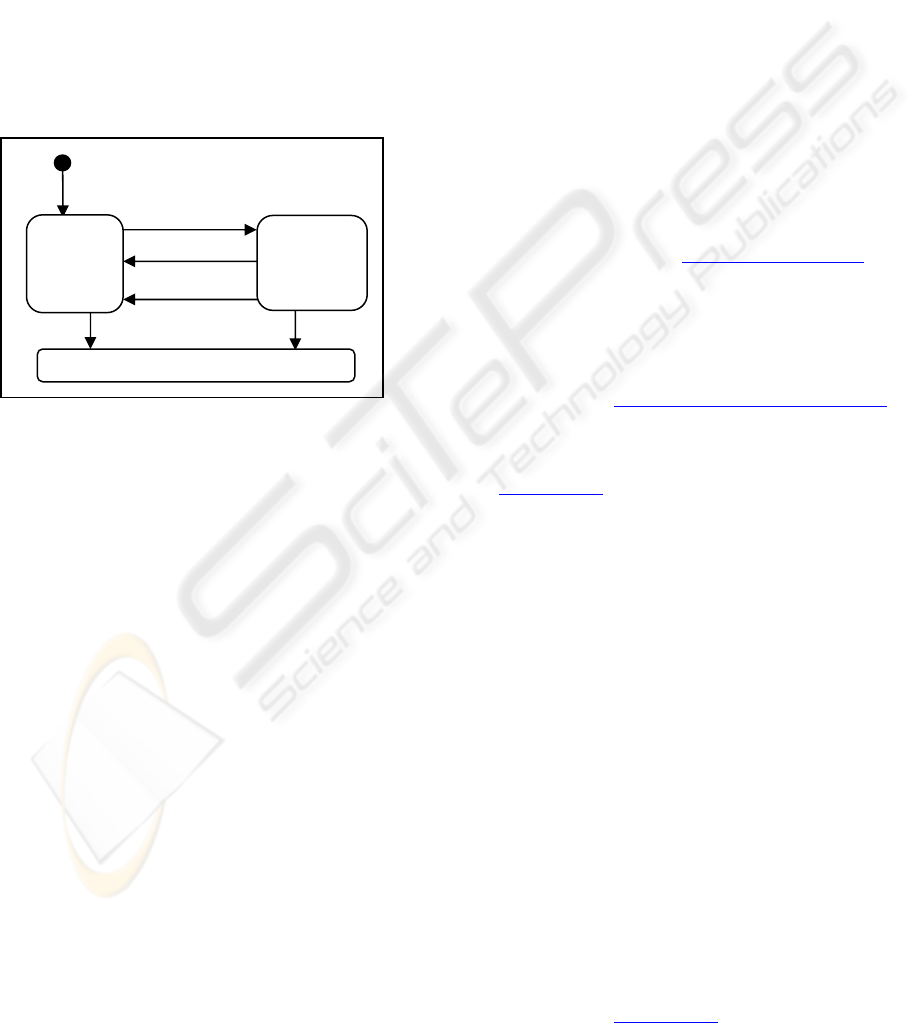
Contrast this with the way this small problem
would be modelled using the Executable UML
approach. Without the ability to derive states, the
state transition diagram for a Person would need to
reflect all the reasons for a transition from the
married to single state, as shown in Figure 10.
Figure 10: “Executable UML” State Diagram for Person
In this solution, if a married person dies, it is
necessary for some object to send a message to the
spouse to announce the death and fire the “Spouse
Dies” transition. Similarly, the Dissolve event must
be sent to both partners in the marriage. In general, a
single event must be sent to, and reflected in,
multiple objects to keep their states synchronized.
In the language of the new UML version 2
standard (OMG, 2003b p. 455), the state machines
defined for the mixin based approach in Figures 3, 4
and 7 are pure “Protocol State Machines”, as the
diagrams are only concerned with defining the state
or states in which it is possible for an event to occur.
Because of the presence of state synchronization
transitions, Figure 10 is not a Protocol State
Machine but something more complex. This can be
seen clearly by noting that whether or not a person
can die is, in the real world, completely
unconstrained by the existence or state of that
person’s spouse. In other words, the transition
“Spouse Dies” in Figure 10 has no protocol
significance.
The complexity involved in sending the same
event to multiple objects to achieve state
synchronization, combined with the stricture that an
object is modelled with a single state transition
diagram, can cause the diagrams to become large
and hard to understand when modelling objects with
complex behaviour. Protocol State Machines,
constructed by composing mixins, provide a more
scalable approach because the individual state
diagrams remain small and relatively simple.
The importance of derived attributes in reducing
redundancy in the information schema of a model is
well known and accepted. Using mixins which may
have derived states extends the same idea to state
transition based behaviour modelling.
6 FURTHER WORK
Our interest is in the use of executable
behaviourable modelling to validate models at an
early stage in the development lifecycle. We believe
that models built using the mixin based approach
described in this paper are well suited for this
purpose, and are developing software that supports
direct execution of such models. Further information
about this can be found at
www.metamaxim.com.
PERSON
Born
Marr
y
REFERENCES
Soley, R., 2002. Presentation: MDA: An Introduction.
Retrieved October 2003 from the Object Management
Group website:
www.omg.org/mda/presentations.htm.
OMG, 2003a. UML 1.5 with Action Semantics, Document
reference formal/03-03-01 March 2003. Available
from the Object Management Group website:
www.omg.org.
Harel, D., 1987. Statecharts: A visual formalism for
complex systems. In Science of Computer
Programming, no. 8,1987, pp. 231-274.
Mellor, S., and Balcer, M., 2002. Executable UML: A
Foundation for Model-Driven Architecture. Addison
Wesley, 2002.
Jackson, M., 1995. Software Requirements and
Specifications: A lexicon of Practice, Principles and
Prejudices. Addison Wesley, 1995.
McNeile, A., and Simons, N., 2003. State Machines as
Mixins. In The Journal of Object Technology, vol. 2,
no. 6, November-December 2003, pp. 85-101.
Hoare, C., 1985. Communicating Sequential Processes.
Prentice-Hall International, 1985.
D’Souza, D., and Wills, A., 1998. Objects, Components,
and Frameworks with UML. The Catalysis Approach.
Addison Wesley, 1998.
Cook, S., and Daniels, D., 1994. Designing Object
Systems. Object-Oriented Modelling with Syntropy.
Prentice Hall, 1994.
OMG, 2003b. UML 2.0 Superstructure Final Adopted
specification, Document reference ptc/03-08-02
August 2003. Available from the Object Management
Group website:
www.omg.org.
S
p
ouse Dies
Single
married
Die
dead
MIXIN BASED BEHAVIOUR MODELLING - An example based on composed state machines
183
