
CONVERTING LEGACY RELATIONAL DATABASE INTO XML
DATABASE THROUGH REVERSE ENGINEERING
Chunyan Wang Anthony Lo Reda Alhajj Ken Barker
Advanced Database Systems and Applications Lab
Department of Computer Science
University of Calgary
Calgary, Alberta, CANADA
Keywords:
XML schema, relational schema, schema conversion, legacy database.
Abstract:
XML (eXtensible Markup Language) has emerged and is being gradually accepted as the standard for data
interchange over the Internet. Since most data is currently stored in relational database systems, the problem of
converting relational data into XML assumes special significance. Many researchers have already done some
accomplishments in this direction. They mainly focus on finding XML schema (e.g., DTD, XML-Schema, and
RELAX) that best describes a given relational database with a corresponding well-defined database catalog
that contains all information about tables, keys and constraints. However, not all existing databases can provide
the required catalog information. Therefore, these applications do not work well for legacy relational database
systems that were developed following the logical relational database design methodology, without being
based on any commercial DBMS, and hence do not provide well-defined metadata files describing the database
structure and constraints. In this paper, we address this issue by first applying the reverse engineering approach
described in (Alhajj 2003) to extract the ER (Extended Entity Relationship) model from a legacy relational
database, then convert the ER to XML Schema. The proposed approach is capable of reflecting the relational
schema flexibility into XML schema by considering the mapping of binary and nary relationships. We have
implemented a first prototype and the initial experimental results are very encouraging, demonstrating the
applicability and effectiveness of the proposed approach.
1 INTRODUCTION
XML is emerging as the standard format for data ex-
change between different partners. Since most of
the data nowadays reside in relational databases, it
is important to automate the process of generating
XML documents containing information from exist-
ing databases. Of course, one would like to pre-
serve as much information as possible during the
transformation process. The Relational-to-XML con-
version involves mapping the relational tables and
attributes names into XML elements and attributes
names, creating XML hierarchies, and processing val-
ues in an application specific manner. Researcher
mostly considered transforming relational databases
that have rich corresponding catalogs. However, a
large number of the existing relational databases are
classified as legacy and the conversion of legacy rela-
tional databases has received little attention. Legacy
databases are characterized by old-fashioned architec-
ture, non-uniformity resulting from numerous exten-
sions, and lack of the related documentation.
Realizing the importance of converting legacy
databases into XML documents, we have developed
a method that successfully handles the process. Our
approach highly benefits from our previous finding
on reverse engineering of legacy databases detailed
in (Alhajj 2003). It leads to identifying and under-
standing all components of an existing database sys-
tem and the relationships between them. Two basic
steps are identified in the process of converting legacy
databases into XML documents. First, reverse en-
gineering is employed to deduce information about
functional dependencies, keys and inclusion depen-
dencies; the process involves reconstructing the ER
model from an existing legacy database. Second, the
obtained ER model is transformed into XML schema
in a process known as forward engineering. Finally,
our approach handles all type of relationships allowed
in the ER model, including many-to-many and n-ary
relationships.
The rest of the paper is organized as follows. Re-
lated work is discussed in Section 2. Section 3 is an
216
Wang C., Lo A., Alhajj R. and Barker K. (2004).
CONVERTING LEGACY RELATIONAL DATABASE INTO XML DATABASE THROUGH REVERSE ENGINEERING.
In Proceedings of the Sixth International Conference on Enterprise Information Systems, pages 216-221
DOI: 10.5220/0002645602160221
Copyright
c
SciTePress
overview of the reverse engineering process to extract
ER model from the existing relational database; for
more details, the reader is referred to (Alhajj 2003).
ER model to XML schema conversion is presented in
Section 4. A closer look at the developed approach
and the implemented prototype is given in Section 5.
Section 6 is the conclusions.
2 RELATED WORK
There exist several tools that enable the composition
of XML documents from relational data, such as IBM
DB2 XML Extender, SilkRoute, and XPERANTO.
XML Extender (Cheng and Xu 2000) serves as a
repository for XML documents as well as their Doc-
ument type declarations (DTDs), and also generate
XML documents from existing data stored in rela-
tional database. It is used to define the mapping of
DTD to relational tables and columns. XSLT and
Xpath syntax are used to specify the transformation
and the location path. SilkRoute (Fernandez, Tan and
Suciu 2000) is described as a general, dynamic, and
efficient tool for viewing and querying relational data
in XML. XPERANTO (Carey et al 2000) is a middle-
ware solution for publishing XML; object-relational
data can be published as XML documents. It can
be used by developers who prefer to work in a “pure
XML” environment. However, the mapping from the
relational schema to the XML schema is specified by
human experts. Therefore, when a large relational
schema and corresponding data need to be translated
into XML documents, a significant investment of hu-
man effort is required to initially design the target
schema. Finally, the work described in (Lee et al
2001) requires knowing the catalog contents in order
to extract the relational database schema. The conver-
sion of Relational-to-ER-to-XML has been proposed
in (Fong, Pang and Bloor 2001). This reconstructs the
semantic model, in the form of ER model, from the
logical schema capturing user’s knowledge, and then
converts it to the XML document. However, many-to-
many (M:N) and nary relationships are not considered
properly. Finally, DB2XML (Turau 1999) is a tool
for transforming data from relational databases into
XML documents; DTDs are generated describing the
characteristics of the data making the documents self
contained and usable as a data exchange format.
Our approach is different from the above men-
tioned approaches; we focus on legacy relational
databases. We adopt our reverse engineering ap-
proach proposed in (Alhajj 2003) to extract a seman-
tically rich ER model from the given legacy relational
database, and then we convert the ER model to XML
schema; we consider M:N and n-ary relationships.
3 EXTRACTING ER MODEL
FROM LEGACY DATABASE
In this section, we present an overview of the reverse
engineering process described in (Alhajj 2003). We
will show the results obtained for the following run-
ning example.
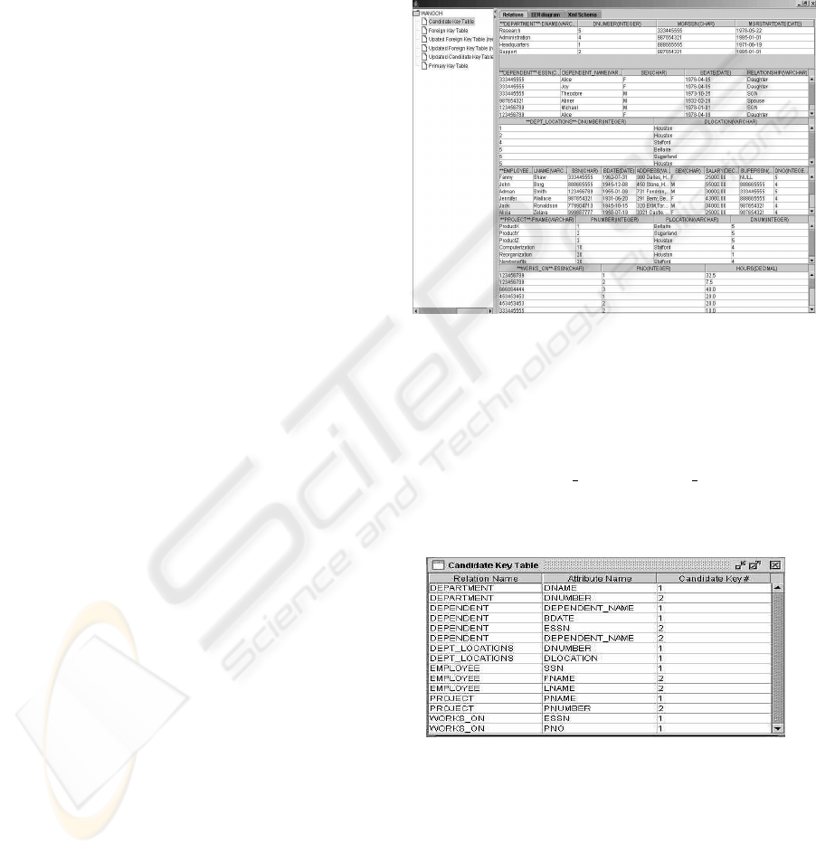
Figure 1: Example COMPANY relational database
Example 3.1 Consider the COMPANY database
shown in Figure 1. This database contains six ta-
bles: EMPLOYEE, DEPENDENT, PROJECT, DE-
PARTMENT, WORKS ON, and DEPT LOCATIONS;
and each table contains tuples some of which are
shown in Figure 1.
Figure 2: Possible candidate Keys of all example relations
The first step is to extract all candidate and
foreign keys found within the relations. The
CandidateKeys table shown in Figure 2 contains all
possible candidate keys of the relations. The Candi-
date Keys# can be used to keep track of having the
same attribute participating in more than one candi-
date key.
CONVERTING LEGACY RELATIONAL DATABASE INTO XML DATABASE THROUGH REVERSE
ENGINEERING
217
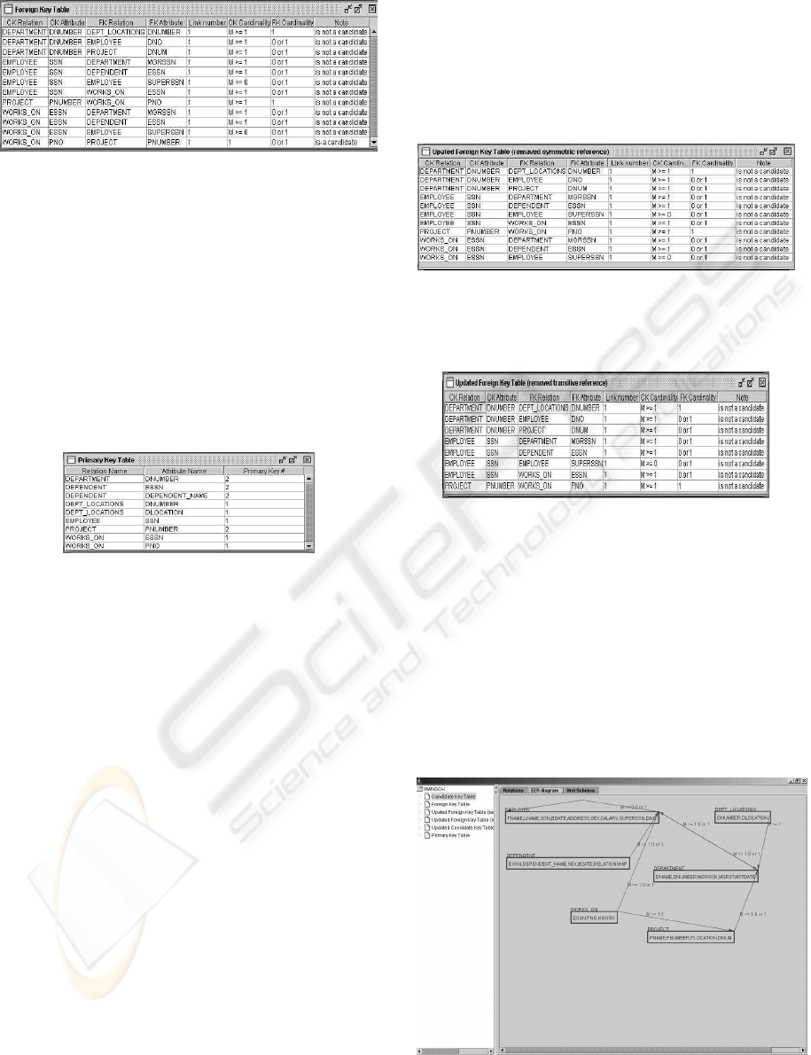
Figure 3: Foreign Keys and their corresponding candidate
keys
The F oreignKeys table shown in Figure 3 con-
tains all pairs of attributes such that the first attribute
is part of a candidate key in a certain relation and the
second attribute is part of a foreign key, a represen-
tative of the first attribute within any of the relations.
Link# is to differentiate different foreign keys in the
same relation. Foreign keys are numbered so that all
attributes within the same foreign key are assigned the
same sequence number.
Figure 4: Primary keys for all the example relations
In general, a relation may have a set of candidate
keys. One candidate key is chosen as the primary key
by checking corresponding foreign keys. For relations
that have multiple candidate keys, the primary key is
selected to be the candidate key that appears in the
first column of ForeignKeys. The P rimaryKeys ta-
ble for the example COMPANY database is shown in
Figure 4.
The information in ForeignKeys is used in con-
structing what is called the Relational Intermediate
Directed (RID) Graph, which present all possible
unary and binary relationships between relations in
the given relational schema. In the RID graph, each
node represents a relation and two nodes are con-
nected by a link to show that a foreign key in the
relation that corresponds to the first node represents
the primary key of the relation that corresponds to the
second node.
As described in (Alhajj 2003), the cardinality of a
relationship in the RID graph is determined as fol-
lows. A link is directed from R
2
to R
1
to reflect the
presence of the primary key of R
1
as a foreign key in
R
2
; so, its cardinality is: 1:1 if and only if at most one
tuple from R
2
holds the value of the primary key of a
tuple from R
1
; and M:1 if more than one tuple from
R
2
hold the value of the primary key of a tuple from
R
1
.
The employed process decides also on the mini-
mum and maximum cardinalities at both sides of the
link by investigating whether the link is optional or
mandatory on each side.
Figure 5: ForeignKeys after eliminating symmetry
Figure 6: ForeignKeys after eliminating transitivity
Analyzing the information in Figure 3, it can be
easily observed that it contains some extra informa-
tion because a foreign key is allowed to play the
role of a candidate key and this leads to two sym-
metric and transitive references. Such extra informa-
tion is deleted as described in (Alhajj 2003). The
CandidateKeys table for the example COMPANY
database after deleting symmetric and transitive ref-
erences are shown in Figures 5 and 6, respectively.
Figure 7: RID graph of the COMPANY database
ICEIS 2004 - DATABASES AND INFORMATION SYSTEMS INTEGRATION
218

Eliminating symmetric and transitive references
lead to an optimized RID graph. The optimized RID
graph is analyzed further to identify relationships with
attributes, M:N and nary relationships, if any. The re-
maining unary and binary relationships are without
attributes, and are represented by direct connections
between nodes in the optimized RID graph. They are
all classified as 1:1, or M:1. The optimized RID graph
for the example COMPANY database is shown in Fig-
ure 7.
4 CONVERTING ER MODEL TO
XML SCHEMA
In this section, we present the proposed process for
translating a conceptual schema (presented as RID
graph) into XML schema. The process in pseudo-
code is depicted in Algorithm 4.1. Algorithm 4.1 (ER
Model to XML Schema Conversion)
Input: The RID graph
Output: The corresponding XML schema
Step:
Step 1: Translate each entity in the ER model into a
complex-type in XML schema.
Step 2: Map each attribute in every entity into a subele-
ment within the corresponding complex-type.
Step 3: Create a root element and insert each entity in
the ER model as a subelement with the corresponding
complex-type.
Step 4: Use “key” and “keyref” to map each relationship
between any two entities.
EndAlgorithm
In order to convert an ER model to XML schema by
Algorithm 4.1, we need to go through the four steps
as detailed next:
• Each entity E of the ER model is translated into an XML
complex-type of the same name E in the XML schema.
In each complex-type E, there is only one empty element.
There will be several subelements inside the empty ele-
ment. For example, the PROJECT entity is translated
into a complex-type named “PROJECT
Relation”. The
empty element is called “PROJECT”.
<complexType name=“PROJECT
Relation” >
<sequence>
<element name=“PROJECT”
type=“r:PROJECT
Type”
maxOccurs=“unbounded”/>
</sequence>
</complexType>
<complexType name=“PROJECT
Tuple”>
<sequence>
. . . . . .
</sequence>
</complexType>
The cardinality constraint in the ER model can be expli-
cated by associating two XML built-in attributes, also
called indicators, namely “minOccurs” and “maxOc-
curs”, with subelements under the XML complex-Type.
The “maxOccurs” indicator specifies the maximum num-
ber of times a subelement can occur. “maxOccurs” =
“unbounded” indicates the element may appear more
than once. The “minOccurs” indicator specifies the min-
imum number of times a subelement can occur. The de-
fault value for both the “maxOccurs” and the “minOc-
curs” attributes is 1. If we want to specify a value only
for “minOccurs”, it must be either 0 or 1. Similarly, if
we want to specify a value only for the “maxOccurs”, it
should be greater than or equal to 1. If both “minOccurs”
and “maxOccurs” are omitted, then the subelement must
appear exactly once.
• In step 2 of Algorithm 4.1, each attribute A
i
of the en-
tity E is mapped into a subelement of the corresponding
complex-type E. For example, the PROJECT entity is
mapped into a complex-type named “PROJECT
Tuple”.
Inside the “PROJECT
Tuple” complex-type, there are
several subelements such as PNAME, PNUMBER, PLO-
CATION, and DNUM. They are the attributes of the
“PROJECT” entity. The XML schema of the PROJECT
entity is:
<complexType name = “PROJECT Tuple”>
<sequence>
<element ref=“r:PNAME” />
<element ref=“r:PNUMBER” />
<element ref=“r:PLOCATION”/>
<element ref=“r:DNUM”/>
</sequence>
</complexType>
The <sequence> specification in the XML schema
captures the sequential semantics of a set of subele-
ments. For instance, in the <sequence> given above,
the subelement PNAME comes first, followed by PNUM-
BER, and then PLOCATION, with DNUM at the end.
These subelements must appear in instance documents in
the same sequential order as they are declared here. XML
schema also provides another constructor called <all>,
which allows elements to appear in any order, and all the
elements must appear once or not at all.
• In step 3 of Algorithm 4.1, each entity is mapped into
the XML schema. We first need to create a root ele-
ment that represents the entire given legacy relational
database. We create the root element as a complex-
type in the XML schema, and then insert each en-
tity as a subelement of the root element. Next is
an example which contains the six entity objects DE-
PARTMENT, DEPENDENT, DEPT
LOCATIONS, EM-
PLOYEE, PROJECT, WORKS
ON. We call the root el-
ement COMPANY:
<element name = “COMPANY”>
<complexType>
<sequence>
<element name=“r:DEPARTMENT
Tpype” />
<element name= “r:DEPENDENT Type” />
<element name=“r:DEPT LOCATIONS Type”
/>
CONVERTING LEGACY RELATIONAL DATABASE INTO XML DATABASE THROUGH REVERSE
ENGINEERING
219

<element name=“r:EMPLOYEE Type” />
<element name=“r:PROJECT Type” />
<element name=“r:WORKS ON Type” />
</sequence>
</complexType>
</element>
Compared to DTD, the XML schema provides a more
flexible and powerful mechanism through “key” and
“keyref”, which share the same syntax as “unique” and
also make referential constraints possible in XML docu-
ments.
• In step 4 of Algorithm 4.1, we use the elements “key”
and “keyref” to enforce the uniqueness and referen-
tial constraints among the data. According to (?), the
“key” element specifies an attribute or element value as
a key (unique, non-nullable, and always present) within
the containing element in an instance document; and
the “keyref” element specifies foreign keys, i.e., an at-
tribute or element value correspond to that of an al-
ready specified key or unique element. The “key” and
“keyref” elements replace and extent the capability of
“ID”, “IDREF” and “IDREFs” in DTD. They are among
the great features introduced in XML schema. Also,
we can use “key” and “keyref” to specify the unique-
ness scope and multiple attributes to create the composite
keys. Here is an example:
<key name = “PROJECTPrimaryKey”>
<selector xpath=“r:PROJECT/r:PROJECT”/>
<field xpath=“PNUMBER”/>
</key>
<key name=“WORKS
ON”>
<selector xpath=“r:WORKS ON/r:WORKS ON”/>
<field xpath=“ESSN”/>
<field xpath=“PNO”/>
</key>
<keyref name = “PROJECTPNUM-
BER
WORKS ONPNOReference”
refer=“r:PROJECTPrimaryKey”>
<selector xpath=“r:WORKS
ON/r:WORKS ON”/>
<field xpath=“PNUMBER”/>
</keyref>
In this example, we first specify the primary key for
each entity in the ER model. From the ForeignKeys
table, we know that PNUMBER is the primary key of
PROJECT entity; ESSN, and PNO together form a com-
posite primary key of WORKS
ON entity. PNUMBER is
a foreign key of WORKS
ON, so we use Keyref to spec-
ify the foreign key relationship between PROJECT and
WORKS
ON entities.
5 A CLOSER LOOK AT THE
DEVELOPED APPROACH
In this section, we describe the overall structure of our
implementation. The purpose of this section is not to
describe details of the code, but to grant the readers
an overview of the system. We have two main com-
ponents: extracting ER model from the given legacy
relational database system and converting ER model
to XML schema.
The prototype has been implemented using Java.
In addition to the fact that we are familiar with Java,
reasons for choosing Java include: 1) It is an object-
oriented language, and hence it is easy to program in
Java. 2) We can use JDBC driver to connect to the
database, also there are some useful functions we can
use for doing operations in the database. 3) We can
use JDOM to obtain the XML schema.
Figure 8: The output XML schema
We have tested our algorithms on the contents the
COMPANY database in Example 3.1. The output
XML schema for the COMPANY database is shown
in Fig. 8. This supports the correctness, effectiveness
and applicability of our approach.
We also test our approach on the contents of
the SAMPLE database in DB2 and the NorthWind
database in MS Access 2000, we neglected the cat-
alog contents for both databases in order to test the
reverse engineering process. It takes around 5 min-
utes for the SAMPLE database, and almost an hour
for the NorthWind database. This is normal because
we expect the time to increase when the size of the
tested database increases. Compared to the SAMPLE
database, it takes much longer time to test the North-
Wind. The main reason is that NorthWind contains 8
tables, many attributes in some of tables, and a lot of
records in each table. Most of the time is spent on
analyzing the contents of the tables and deriving the
ER model. Even if a human is asked to do the same
job, the process becomes unmanageable manually as
the size and complexity of the database increases.
To summarize, the proposed framework consists of
the following major components to automatically ex-
tract the ER model from the given legacy relational
ICEIS 2004 - DATABASES AND INFORMATION SYSTEMS INTEGRATION
220

database, and then transfer it into XML schema.
Data layer, which is a legacy relational database that
stores all the data to be analyzed and converted into
XML.
Reverse engineering layer, which extracts an ER model
from the input database.
Transformation layer, which transfers the ER model
into XML schema.
Graphical output layer, which shows the result for each
step (i.e., foreign keys table, candidate keys table, pri-
mary keys table, RID graph, and XML schema, etc).
Undoubtedly, reconstructing an ER model from a
legacy database, and writing an XML schema file
both are heavy and tedious jobs, especially for a large
real application. The users could be relieved of this
heavy load by using our framework. On the other
hand, the users’ knowledge could also be involved in
this system. However, compared to reconstructing an
ER model and writing a long XML schema file from
scratch, the human’s mental workload is greatly re-
duced with our framework.
Our framework presented in this paper has the fol-
lowing advantages compared to the work described
in (Kleiner and Lipeck 2001), where the authors show
how to obtain a DTD for data whose structure is de-
scribed by a conceptual data model. In brief, they
present the translation of all constructs of the ER
model to DTDs and integrate them into an algorithm.
• Our framework could be used not only for a normal re-
lational database system, but also for a legacy relational
database system.
• We choose XML schema instead of DTD; XML schema
provides a more flexible and powerful mechanism than
DTD. We can easily present each entity in the ER model
by using XML complex-Type. And also we can use
“key” and “keyref” to declare the attributes uniqueness,
composite keys, and referential constraints.
• Our prototype gives users a direct visualization of the
output obtained from each phase of the process.
• The expected human workload is considerably reduced
compared to the approach described in (Kleiner and
Lipeck 2001).
6 CONCLUSIONS
In this paper, we presented a novel approach to ex-
tract an ER model from a legacy relational database,
and then convert the ER model to a corresponding
XML schema; i.e., by applying reverse engineering
followed by forward engineering. We preserve as
much information as we can from the given relational
schema to the XML schema. Our approach not only
works for commercial relational databases but also for
legacy relational databases. We use the XML schema
instead of the DTD schema; the advantages of this is
that we can use a complex-type to represent each re-
lational table; “key” and “keyref” are great features
introduced in XML schema. They replace and extend
the capability of “ID”, and “IDREF” and “IDREFs”
in DTD. We use “key” and “keyref” to specify the re-
lationship between tables, the uniqueness scope and
multiple attributes to create the composite keys. We
can also determine M:N and n-ary relationships, so
we produce a XML schemas and XML documents
for the data stored in databases without knowing any-
thing about the catalog information. Currently, we are
working on improving the prototype to provide flex-
ible visual querying facility by allowing the user to
choose from the displayed RID graph the tables and
even the attributes to be displayed in XML format.
REFERENCES
R. Alhajj, “Extracting the Extended Entity-
Relationship Model from a legacy Relational
Database, ” Information Systems, Vol.28, No.6,
pp.597-618, 2003.
M. Carey, et al, “XPERATO: Publishing Object-
Relational Data as XML,” Proc. of the Interna-
tional Workshop on Web and Databases, May
2000.
J. Cheng and J. Xu, IBM DB2 XML Extender, IBM
Silcom Valley, February, 2000.
M.F. Fernandez, W.C. Tan, and D. Suciu, “SilkRoute:
Trading between Relational and XML,” Proc.
of the International Conference on World Wide
Web, May 2000.
J. Fong, F. Pang, and C. Bloor, “Converting Rela-
tional Database into XML Document,” Proc. of
the International Workshop on Electronic Busi-
ness Hubs, pp61-65, Sep. 2001.
G. Kappel, et al, “X-Ray - Towards Integrating XML
and Relational Database Systems,” Proc. of the
International Conference on Conceptual Model-
ing, pp. 339-353, Salt Lake City, UT, Oct. 2000.
C. Kleiner and U.W. Lipeck, “Automatic Genera-
tion of XML DTDs from Conceptual Database
Schemas,” University of Hannover, Germany,
Sept 2001.
D. Lee, et al, “Nesting based Relational-to-XML
Schema Translation,” Proc. of the International
Workshop on Web and Databases, May 2001.
M. Mani, D. Lee, and R. Muntz, “Semantic Data
Modeling using XML Schemas,” Department of
Computer Science, University of California, Los
Angeles, 2001.
V. Turau, “Making Legacy Data Accessible for XML
applications,” 1999, http://www.informatik.fh-
wiesbaden.de/ turau/ps/legacy.pdf.
CONVERTING LEGACY RELATIONAL DATABASE INTO XML DATABASE THROUGH REVERSE
ENGINEERING
221
