
REPRESENTATION OF BUSINESS INFORMATION
FLOW WITH AN EXTENSION FOR UML
From Business Processes to object-orientated Software Engineering
Oliver Daute
University of Hagen, Universitaetsstrasse 1, 58084 Hagen, Germany
Keywords: Business Process, Requir
ement Engineering, Software Engineering, Use Case Diagram, UML
Abstract: The use of enterprise software solutions is getting increasingly
important. Today thousands of users are able
to work in an integrated enterprise solution. The requirements of software systems have changed
dramatically in quality and quantity in the last decades. While the know-how in technology was the main
factor for success in the past, today much more effort is needed and involved to understand what the
customer wants. At this point Business Process Engineering became an important way to describe the
business and system requirements. It focuses on requirements, terminology, processes, dependencies, and on
the Business Information Flow, which is the subject of this article. There are several procedures and
methodologies available for modeling business process requirements. Most of them are focused on a
particular area of business and utilize a special modeling technique often used to customize a standard
software solution. A better way, specifically for non-standard software solutions is the use of an
independent modeling language like the UML. The UML is well established in the domain of object
orientated software development (Meta, 2003). For business process modeling more investigations are
required, especially on how to represent business information flow. An appropriate way, as we propose
here, is to add business information flow to UML Use Case Diagrams.
1 INTRODUCTION
The software development process ranging from the
business processes to a usable enterprise solution is
an interesting and important field with increasing
attention from researchers and industries. There are
still open questions, especially how to represent
business process requirements. An important aspect
is the Business Information Flow (BIF), which is
investigated here.
This article is about the representation of BIF,
whi
ch is part of the overall Business Process Flow.
We add BIF to use case diagrams to improve the
validation process and to provide essential
information for business analysts, customers and
software developers. The combination of use case
diagrams and information flow is easy to read and
simple to understand.
Various modeling languages are available to
descri
be business process requirements. Some of
them are used to customize a pre-configured
software solution and can only be used by
experienced designers. Usually the process
description is not reusable and the effort invested
during the analysis phase is lost.
The Un
ified Modeling Language (UML) is a
reasonable alternative. UML is a well-known
modeling language and used in many software
development projects. UML is independent of any
software solution and requires no specials tools.
Unfortunately UML is not expressive enough for
Busine
ss Process Engineering (BPE), in particular to
represent the information flow (Ambler, 2000).
Therefore an extension for UML Use Case Diagrams
will be presented, which makes it simpler to
efficiently represent the flow of information.
The proposed extensions belong to a Business
Pro
file, called 4BP. The 4BP profile provides
several representation symbols for business process
modeling. For the representation of BIF we will
introduce some symbols out of 4BP. The extensions
will help us to understand which parameters affect a
single use case.
A further benefit of the extension is evident in the
val
idation process. For a software developer it is
569
Daute O. (2004).
REPRESENTATION OF BUSINESS INFORMATION FLOW WITH AN EXTENSION FOR UML - From Business Processes to object-orientated Software
Engineering.
In Proceedings of the Sixth International Conference on Enterprise Information Systems, pages 569-572
DOI: 10.5220/0002651305690572
Copyright
c
SciTePress
important to find as much as possible of information
in one place; so for the customer, who is interested if
his business requirements are described properly.
The combination of the UML use cases diagrams
with the extension is an appropriate way,
understandable, for business analysts, software
developers, as well for the customers. All
information can be depicted in one diagram, use
cases, actors, input & output data, global values, as
well as triggers.
In the following sections you will find a brief
overview about Business Process Engineering,
followed by the Business Information Flow, the
UML Use Case Diagrams and the Representation of
Business Information Flow. A small example at the
end shows how to apply the extension.
2 ABOUT BUSINESS PROCESS
ENGINEERING
Business process engineering is an important
discipline as a result of the growth of informational
enterprise system. When developing an entire
enterprise solution, BPE is the very first step to
capture and structure the business requirements in an
adequate way.
BPE describes the way what an enterprise does. It
describes the business from the customer’s
perspective. The business processes consist of two
different parts, a static system structure and a
dynamic system behavior.
The static system structure consists of business
sections divided into business components. The
business components contain business objects.
The dynamic system behavior consists of data,
information, global values, triggers and flows of
input & output data. This is the BIF, which is added
successively to the static structure during the
requirement analysis phase.
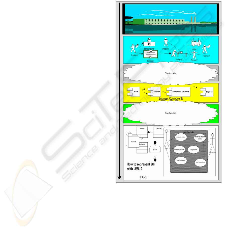
Figure 1 gives an idea of business process
engineering. To reduce the complexity only some
levels are shown. Beginning with the enterprise,
several phases of analysis, modeling and abstraction
are needed until all requirements are represented
with UML.
The BIF (see second layer from top) contains data
used by the business processes during process
execution. The data is exchanged by the processes or
flows into central databases.
Many business requirements can already be
represented with UML, but a question remains: How
to represent BIF with UML?
For enterprise solutions, such as ERP systems,
the engineering process from the business processes
to the final software solution is fully supported. The
representation of the information flow is already part
of the solution (e.g. as integrated databases and data
flow management systems). The disadvantage is the
use of proprietary representation techniques. Most
techniques are not compatible to each other and
make it difficult to reuse a business process
description for a different purpose, e.g., for quality
management (ISO 9002). Valuable work done by
business analysts, users and developers during the
requirement analysis phase is lost.
Figure 1: From Business Processes Engineering to
object-orientated Software Engineering
Especially for non-standard solutions, UML is an
alternative. It is widely accepted and provides
already different kind of shapes for the
representation of the static structure view and the
dynamic behavior; shapes like components, packets,
actors, use cases, classes, associations and
generalization etc.
ICEIS 2004 - INFORMATION SYSTEMS ANALYSIS AND SPECIFICATION
570
Additional shapes and symbols are required for
BPE (Scheer, 2003; Ambler, 2000) to support the
representation of business requirements.
3 BUSINESS INFORMATION
FLOW
Inside business information flow data is
transferred, such as documents, lists, reports, a work
order, protocols, company templates or data like the
address of a customer or a supplier.
For business processes (activities) the availability
of information is a precondition for task
performance. For instance, for a room reservation
we need several data about a customer. Therefore it
is important to investigate the input data and output
data during the requirement analysis phase. While a
business activity performs, the BIF (data) maybe
changed, modified or deleted. Maybe some more
data is generated.
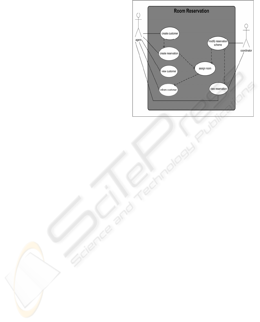
Figure 2: Use Case Diagram
Business information flow consists of Global
Data, which is generally not changed during the
business process activity; Process Data, which is
used or changed during the business activities and is
known as input & output data; and Triggers, which
are used to control business processes, e.g. to enable
or disable a business use case.
The task of business information flow is to
transport data between the business processes. A
special representation for BIF is required.
4 USE CASE DIAGRAM
A UML use case diagram covers information about
actors, use cases, extend and include relations and
inheritance (see figure 2), but does not show the
influencing business parameters, like input and
output data or globally used data (Scheer, 2003).
Because of the missing focus on business
processes, especially the missing focus on BIF, use
case diagrams are not very useful for BPE. The
effort to work with the diagrams is too high
compared to the result in addition. Too few
information are available about the influencing
parameter.
Adding BIF to UML use case diagrams, as shown
next section will enrich the diagrams with valuable
information. It improves the validation process and
provides essential information for business analysts,
software developers, as well for the customers. It is
likely that use case diagram will be used much more
in future.
5 REPRESENTATION OF
BUSINESS INFORMATION
FLOW
The symbols, presented here are also used in a
similar way by IDEF (Integration Definition For
Function Modeling), a family of methods for
enterprise modeling and analysis.
For the representation of business information
flow we introduce symbols for input & output data
(process Data, like documents, list, reports), as well
as a symbol for triggers (process control), which are
used to control business use cases and we introduce
a symbol for global data (global data is not modified
in general).
Table 1 summarizes the new symbols for BIF. An
arrow is used for input & output data, indicating the
direction of data flow. Close to the arrow the type
and name of the data is specified. If the number of
data exceeds the available space in the diagram, a
reference should be used instead of the full names.
The point the arrows are connected to the use case
symbol is optional.
For a trigger we use a single line. The name of a
trigger is placed on top of the symbol. Because
triggers have a special function within the flow of
business information, it is recommended to place
triggers on top of or below of the use case symbol.
The global data symbol is also recommended to
put on top of the use case symbol and is represented
as a line as well. The designator of global data is
placed beside the symbol.
REPRESENTATION OF BUSINESS INFORMATION FLOW WITH AN EXTENSION FOR UML: From Business
Processes to object-orientated Software Engineering
571
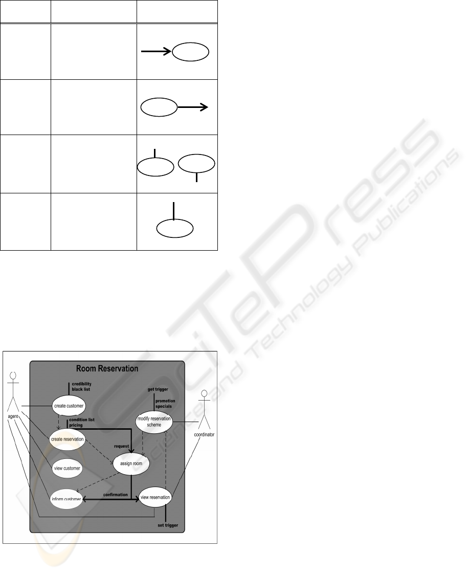
Table 1: Types of Business Information Flow
type description symbol
<Input> Represents input
data, such as lists,
documents and
information.
<Output> Represents output
data, such as lists,
documents and
information.
<Trigger> Represents a
Trigger. Enables or
disables a business
use case.
<Global> Represents global
data. Global values
are not changed in
general.
To save symbols and maintain clarity, a “trigger”
and a “global” can be combined and depicted in one
symbol.
Figure 3 shows an example “Room Reservation”,
a use case diagram added with business information
flow.
An agent for instance “creates a reservation” (use
case). To make a reservation “the condition list” and
“pricing tables” are needed. This kind of business
information flow is global data and is represented
with an undirected small line on top of the use case.
If all data is available, such as customer name,
address, timeframe of stay and category then a
“request” is send to “assign room” (use case) and the
reservation can be completed. An assignment is
made according to the booked category and a
“confirmation” (output data) is generated. The
“confirmation” is also input data for the use cases
“view reservation” and “inform customer”. The
input and output data, such as “request” and
“confirmation” are represented with an arrow.
<input data>
<output data>
For a trigger, for instance, the use case “modify
reservation scheme” can only be used if a trigger is
set to enable the use case. Triggers are important for
business process controlling.
<get trigger>
<set trigger>
6 CONCLUSION
<global>
We propose an extension of UML to combine
dataflow information with use case diagrams. It is an
easy simple extension with arrows for “input &
output data” and single lines for “triggers” and
“global data”. It provides essential information for
software developers, as well as for the customer and
improves the validation process. The extension in
combination with UML is easy to use in any
software development project and is not dependent
on special software. The business process modeling
is reusable, for instance for quality managements
purposes.
Figure 3: Use Cases Diagram with Business
Information Flow
REFERENCES
Ambler, 2000. The Object Primer, Introduction to
Techniques for Agile Modeling. Ronin International.
IDEF. Family of Methods,
1408 University Dr. East
College Station, TX 77840.
http://www.idef.com.
Sergio de Cesare, Patel, 2001. Business Modeling with
UML. Brunel University, UK.
Jacobson, Booch, Rumbaugh, 1999. The Unified
Modeling Language User Guide. Addison-Wesley.
Geoffrey, 2000. The Business Process Model. Enterprise
Architect.
Meta Group, 2003. Market Research, Worldwide IT
Benchmark Report. METAGroup.
UML, Unified Modeling Language,
http://www.omg.org/
Scheer, 2003. Modellierungsmethoden Metamodelle
Anwendungen. Springer.
ICEIS 2004 - INFORMATION SYSTEMS ANALYSIS AND SPECIFICATION
572
