
A USER-CENTERED METHODOLOGY TO GENERATE VISUAL
MODELING ENVIRONMENTS
Gennaro Costagliola, Vincenzo Deufemia, Filomena Ferrucci and Carmine Gravino
Dipartimento Matematica e Informatica, Universit
´
a di Salerno
84081 Baronissi (SA), Italy
Keywords:
Meta-modeling techniques, Grammar formalisms, CASE tools, Visual modeling languages
Abstract:
CASE tools supporting many activities of the software development process embed visual modeling environ-
ments. Indeed, visual languages are practical means to allow engineers to define models and different views
of software systems. However the effectiveness of visual modeling environments strongly depends from the
process and tools used for their development. In this paper we present a user-centered methodology for the
development of customized visual environments, and a tool to support it. The use of UML meta-modeling
techniques and formal methods characterizes the proposed approach. Moreover, incremental development and
rapid prototyping are ensured by the use of an automatic generation tool that allows designers to focus on
structural features of the target language disregarding the visual environment creation.
1 INTRODUCTION
The observation that the human visual system is more
inclined toward processing visual information rather
than textual one, and the decreasing cost of hardware
technologies and graphics software have caused the
development of a large number of visual languages
in many different application fields. Their use in the
problem solving process allows for the construction
of a problem representation, which gives insight into
the structure of the problem, and helps to find a possi-
ble solution. For that reason, CASE tools embedding
visual modeling environments are widely employed
to support many activities of the software develop-
ment process, such as specification, analysis and de-
sign. Indeed, they allow engineers to devise solutions
and design systems by enabling to construct abstract
models and different views of software systems.
However, the development of visual modeling en-
vironments is a cumbersome and time-consuming ac-
tivity, which requires the adoption of suitable method-
ologies and powerful tools. It is worth noting that
one of the major risks concerned with the develop-
ment of visual environments is the lack of an effec-
tive look and feel due to the unsuitability of the de-
signed icons to resemble their meaning, and/or the
missing correspondence between user’s intention and
visual models interpretation. Such a risk is espe-
cially high for domain specific languages which are
adopted in domain specific software methods (Nokia
Mobile Phones, 1999)(Schmidt et al., 2002). Indeed,
in such a case visual models are constructed by suit-
ably arranging icons representing objects that should
be part of the domain problem space, and be easily
understood by end user by resembling their meaning
through their physical representation.
In this paper we describe a user-centered method-
ology specifically conceived for the development of
customized visual modeling environments and we
propose a tool designed to support this methodol-
ogy. The use of UML meta-modeling techniques and
formal methods characterizes the proposed approach,
which is based on an incremental development and
rapid prototyping. The prototyping is essential be-
cause it is impossible to pre-specify the look and feel
of a visual modeling language in an effective way,
and its use can reduce requirement risks by reveal-
ing errors and omissions. Indeed, since requirements
are usually expressed in the language of the applica-
tion domain, they are often not understood by the de-
signer developing the visual modeling environment.
Thus, in order to enhance the communication be-
tween designer and user, the methodology proposes
to define language requirements using UML class di-
agrams making them more understandable by users
who do not have detailed technical knowledge.
147
Costagliola G., Deufemia V., Ferrucci F. and Gravino C. (2004).
A USER-CENTERED METHODOLOGY TO GENERATE VISUAL MODELING ENVIRONMENTS.
In Proceedings of the Sixth International Conference on Enterprise Information Systems, pages 147-154
DOI: 10.5220/0002652701470154
Copyright
c
SciTePress
The rapid development of the language environ-
ment is essential for adopting a prototyping approach.
To this aim, we propose the use of a grammar-based
tool, named GENIE, that starting from the formal
specification of the language is able to generate the
corresponding visual modeling environment. The
tool extends the ’compiler-compiler’ approach widely
adopted for the generation of programming environ-
ments to visual oriented environments. Moreover, the
choice of a context-free style grammar formalism un-
derlying GENIE allows for an incremental approach
which notably simplifies the definition of visual en-
vironments. Another distinguishing characteristic of
the proposed approach is the adoption of the GXL for-
mat as data representation for visual sentences (Holt
et al., 2000). This choice allows for a more easy in-
tegration of the generated visual environments with
other tools.
The paper is organized as follows. Section 2 il-
lustrates the GENIE system and the design process
supported by it. Section 3 is devoted to present the
development of a visual environment for Data Flow
Diagrams. Related work and final remarks conclude
the paper.
2 THE GENIE SYSTEM
In this section we describe the GENIE (GENerator of
Interoperable visual Environments) system for the au-
tomatic generation of visual modeling environments.
In the following, first we present the methodology un-
derlying the system, and then its architecture.
2.1 The Methodology Underlying
GENIE
It is worth noting that one of the major risks con-
cerned with the development of visual modeling envi-
ronments is the lack of an effective look and feel due
to the unsuitability of the designed icons to resem-
ble their meaning, and/or the missing correspondence
between user’s intention and visual models interpre-
tation. Such a situation can be related to the lack of
a clear and unambiguous comprehension of the user’s
domain and needs, and the inadequacy of the commu-
nication between designer and end user.
In order to reduce such risk and obtain effective
modeling languages a user centered approach is usu-
ally recommended. Such an approach should be
based on rapid prototyping which requires the adop-
tion of effective tools and formalisms. As we show
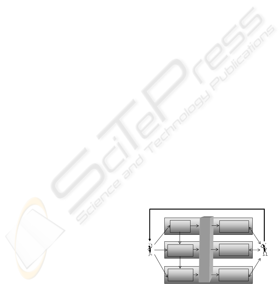
in Figure 1, GENIE can be profitably exploited to
carry out such a task since it supports a design pro-
cess where the user plays a crucial rule. In particu-
lar, such design process is characterized by incremen-
tal and rapid prototyping aspects, and it is based on
the use of UML meta-modeling techniques and for-
mal methods.
Step 1. UML meta-modeling techniques are ex-
ploited during the requirements analysis. In partic-
ular, the designer starts by addressing the tasks con-
cerned with domain understanding and requirements
collection. After analyzing the risks and evaluating
the alternatives (also due to the possible presence of
conflicting end users) the designer provides a high-
level specification of domain requirements in terms of
annotated UML class diagrams. This notation repre-
sents a natural way of reflecting the real world entities
that should be captured by the language, and allows
the designer to describe the aggregation between do-
main objects and to organize them into a hierarchy
that highlights specialization/generalization relation-
ships. Moreover, the meta-model produced in this
phase is enriched with layout information, which is
associated to the classes representing visual symbols
of the modeled language. The specified meta-model
is input to GENIE that generates a first release of the
visual editor by exploiting the visual environments
generator module. Such a facility of GENIE allows
the designer to focus on structural features of the tar-
get language disregarding the visual environment cre-
ation, which is automatically performed by the sys-
tem.
This facilitates the combination of development
and validation, and promotes the iterative design and
interactive prototyping, by providing the capability of
simulating the language in early stages of develop-
ment. This editor is exposed to the user’s judgement,
who can experiment with the environment to verify
the look of the language by editing visual sentences.
Based on the user’s feedback, the designer can refine
the layout of the visual symbols, and resubmit the new
version of the editor to the user’s evaluation giving
rise to an iteration cycle.
Meta
model
Grammar
specification
Semantic
specification
Visual
Editor
Visual Editor
with analyzer
Visual Editor
with compiler
grammar
skeleton
GENIE
End
user
designer
user’s feedback
Figure 1: The design process supported by GENIE.
Step 2. Once the visual editor satisfies the user needs,
the UML specification is validated, and the designer
ICEIS 2004 - INFORMATION SYSTEMS ANALYSIS AND SPECIFICATION
148
carries out the second phase of the proposed method-
ology that is focused on the development of a syntax
analyzer for the target language. To this aim, he/she
again benefits from the availability of GENIE that al-
lows him/her to provide a grammar specification by
refining a previously generated draft, and to obtain
the corresponding parser. The produced visual en-
vironment is exposed to the user’s judgement, who
can experiment with the environment by editing vi-
sual sentences and verifying if they are embedded in
such an environment (i.e., they belong to the language
specified by the grammar). Thus, he/she determines
the aspects with which he/she is satisfied and the ones
which need further enhancement or modification. The
use of the prototype may also allow the user to better
understand and express his/her requirements. Based
on the user’s feedback, the designer can refine the
syntax specification of the language. The refined ver-
sion is submitted again to the user’s evaluation giving
rise to an iteration cycle which is only stopped when
the prototype fully satisfies the user.
Step 3. The third phase concern with the specifica-
tion of the machine interpretation of visual sentences.
In particular, the grammar specification is enriched
with semantic rules in order to map visual sentences
of the language into host-language programs or re-
ports. Furthermore, semantic rules can be specified
to statically analyze semantic properties of the sen-
tences. Again the designer exploits the generator to
obtain the visual modeling environment that besides
the visual editor encompasses a compiler for the lan-
guage. Such an environment can be exploited to ver-
ify the look and feel of the generated visual language,
by editing visual sentences and requiring their inter-
pretation. So, the user can test the system to validate
the visual modeling environment or suggest further
modifications.
Step 4. The final task of the designer is to provide
means for visual language interchanging. Indeed, this
is crucial to ensure a more easy integration of the gen-
erated visual environments with other tools, and this
is an issue especially felt in the context of modeling
languages. In the proposed approach, the issue is ad-
dressed by enriching the grammar specification with
suitable semantic rules able to associate a XML-based
representation to any sentence of the target language.
In the next subsection we will show the GENIE ar-
chitecture and how the proposed system supports de-
signer in carrying out such a task exploiting a versatile
XML approach.
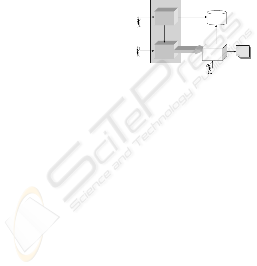
2.2 The GENIE Architecture
GENIE consists of two modules, namely the UML
Class Diagram Environment (CDE), and the Visual
Language Compiler-Compiler (VLCC) system (see
Figure 2). The first environment allows designers to
draw and modify class diagrams, while the second
module assists him/her in the syntactic and seman-
tic specification of the visual modeling language and
automatically generates the corresponding visual en-
vironment.
In the following, first we will describe in more de-
tail the architecture of VLCC, and then we will illus-
trate the main features of the CDE module.
Grammar
Skeleton
XPG with
semantic rules
Annotated
UML
Class
Diagram
Visual model
VLCC
System
GENIE
end user
report/code
GXL
repository
GXL
schema
GXL
instance
Target
Visual Modeling
Environment
UML Class
Diagram
Environment
Figure 2: The architecture of GENIE.
VLCC is a grammar-based visual environment gen-
eration system based on the eXtended Positional
Grammar (XPG) model. The characteristics of such
a grammar model allow VLCC to inherit and extend
to the visual field, concepts and techniques of com-
piler generation tools like YACC (Johnson, 1978). In
particular, the XPG model allows for an extension of
LR parsing (Aho et al., 1985), named XpLR method-
ology, which is able to analyze very complex visual
languages. The architecture of VLCC is shown in
Figure 3.
It consists of three modules, namely the Symbol Ed-
itor, the Production Editor, and the Visual Modeling
Environment Generator.
The designer creates the terminal and the non-
terminal symbols of the grammar by using the Sym-
bol Editor. This editor works in two modes, the draw-
ing mode and the symbol mode allowing the designer
to easily define and customize the icons that will form
the sentence of the target visual modeling environ-
ment. Indeed, in drawing mode the designer can cre-
ate or modify images using the usual graphical edi-
tor facilities. In symbol mode the designer can trans-
form an image into a grammar symbol (terminal or
non-terminal) by adding the syntactic and the seman-
tic attributes, or can modify the syntactic or semantic
attributes of a symbol. The set of terminal and non-
terminal symbols are used by the designer to create
the productions using the Production Editor (see Fig-
ure 3) that allows us to define the grammar in an as-
sistant way.
A distinguishing characteristic of the environments
A USER-CENTERED METHODOLOGY TO GENERATE VISUAL MODELING ENVIRONMENTS
149
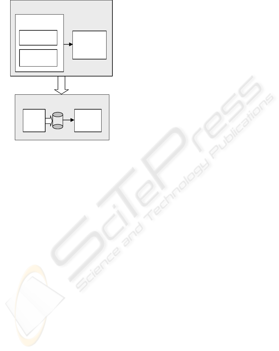
Visual Language Compiler-Compiler
Grammar
Editor
Symbol Editor
Production
Editor
Visual
Modeling
Environment
Generator
Visual Modeling Environment
LR–based
compiler
Visual
Editor
Figure 3: The VLCC architecture.
generated by GENIE is the adoption of GXL (Graph
eXchange Language) format as data representation
for visual sentences. This allows for a more easy in-
tegration of the generated visual environments with
other tools. The choice of GXL has been motivated
by its characteristics of versatility, scalability and ex-
tensibility (Holt et al., 2000)(Winter, 2002). Indeed,
although GXL was designed to be a standard data ex-
change format for graph-based tools it can be used
in the context of visual languages because a graph
structure can be identified in any diagrammatic vi-
sual sentence. Exchanging graphs with GXL deals
with both instance graphs and their corresponding
graph schemas in terms of XML documents (Ex-
tended Markup Language) (Winter, 2002). The graph
schema provides the graph structure, i.e. the defini-
tion of nodes and edges, their attribute schemas and
their incidence structure, and the instance graph rep-
resents a visual sentence.
Thus, GXL allows us to improve interoperability
between visual modeling environments. As a matter
of fact, some groups from industry and research com-
mitted to provide facilities to import and export GXL
documents to their tools (Winter et al., 2002).
It is worth noting that the CDE module forming the
front-end of GENIE has been obtained by exploiting
VLCC. In particular, an XPG specifying the UML
class diagrams language was input to the system to-
gether with suitable semantic rules able to create an
environment which could provide further support to
the designer during the language development pro-
cess. As a matter of fact, the front-end of GENIE
not only assists him/her in the construction of a UML
class diagram representing a high-level specification
of a visual modeling language, but it is also able to
translate such a diagram into a corresponding GXL
schema and a context-free grammar skeleton. Due
to the limit space, the set of rules to accomplish this
translation are not reported here. The GXL schema
produced from the meta-models are stored in the GXL
repository, and will be exchanged together with their
GXL instances, whenever the visual sentence are im-
ported by other GXL-based tools.
3 AN EXAMPLE: GENERATING
AN ENVIRONMENT FOR DFD
In this section we show how to generate a visual mod-
eling environment for Data Flow Diagrams (DFDs)
by using GENIE. DFDs are a graphical notation
which is extensively employed in the software engi-
neering field and provides one of the most success-
fully paradigms underlying several visual program-
ming languages, such as, Show and Tell (Kimura
et al., 1990), LabVIEW (Vose and Williams, 1986),
Vampire (McIntyre, 1995). Languages based on this
model exploit dataflow diagrams to visually depict
dependencies between data and processes. Indeed, in
these diagrams boxes represent processing steps and
data flow along the connecting edges.
Figure 4 shows the meta-model for DFD specified
by using the CDE module of GENIE.
It is worth noting that the UML class diagrams
specified in this phase are by no means concerned
with technical details of language implementation,
but only describe the entities of the problem domain,
and the annotation provides the concrete syntax of the
language, i.e. physic, syntactic and semantic features
of the symbols (see Figure 5). As an example the
class STORE of the diagram in Figure 4 is annotated
with information specifying that the symbol will be
visualized as two parallel lines and will have a label
describing data. Moreover, note that symbols PRO-
CESS, STORE, ENTITY have one attaching region
as syntactic attribute, and symbol EDGE has two at-
taching points as syntactic attributes corresponding to
the start and end points of the edge. Observe that each
attaching region is represented by a bold line and is
identified by the number 1, whereas the two attach-
ing points of EDGE are represented by bullets and are
identified each by a number.
Thus, such UML class diagrams allow for a more
effective communication between designer and end
user, which can benefit from the comprehension of the
specification and make suggestions and modifications
in early phases of visual language development.
ICEIS 2004 - INFORMATION SYSTEMS ANALYSIS AND SPECIFICATION
150
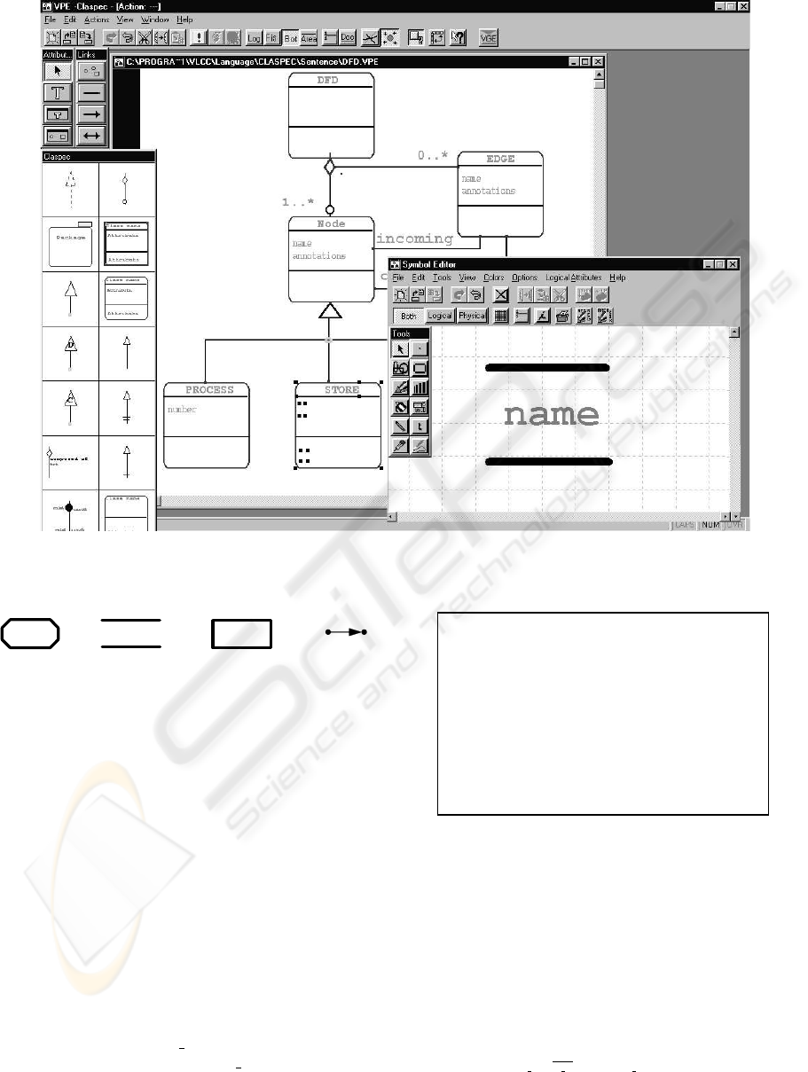
Figure 4: The CDE module of GENIE and the meta-model for Data Flow Diagram language.
1
PROCESS STORE ENTITY EDGE
1
1
2
1
1
Figure 5: The visual representation of symbols of DFD lan-
guage.
GENIE generates a visual editor and translates the
meta-model into a corresponding GXL schema, and a
context-free grammar skeleton that is shown in Figure
6.
In order to construct the XPG productions, the de-
signer identifies the relations used to relate the sym-
bols in the visual sentences by analyzing the annota-
tions on the syntax and the associations of the gram-
mar skeleton. As an example, the associations incom-
ing and outcoming of the skeleton will be specified by
using a relation LINK
h,k
which is a connection rela-
tion defined as: a graphical symbol A is in relation
LINK
h,k
with a graphical symbol B iff attaching re-
gion h of A is connected to attaching region k of B,
and will be denoted as h
k to simplify the notation.
Moreover, we use the notation h k when describing
the absence of a connection between two attaching ar-
eas h and k.
Terminals = {PROCESS, ENTITY, STORE, EDGE}
Non Terminals = {DFD, Node}
Productions = {
(1) DFD ĺ Node
(2) DFD ĺ DFD EDGE incoming Node
(3) DFD ĺ DFD EDGE outcoming Node
(4) Node ĺ PROCESS
(5) Node ĺ STORE
(6) Node ĺ ENTITY
}
Figure 6: The grammar skeleton obtained from the UML
class diagram of Figure 4.
Thus, the following XPG productions can be ob-
tained from the grammar skeleton. Notice that the
superscripts are used to distinguish different occur-
rences of the same symbol.
(1) DFD → Node
∆: (DFD
1
= Node
1
)
(2) DFD → DFD
0
hh1
1i,h1 2ii EDGE 2 1 Node
∆: (DFD
1
= DFD
0
1
− EDGE
1
)
Γ:{(PLACEHOLD; |Node
1
|>1; PLACEHOLD
1
= Node
1
− EDGE
2
)}
A USER-CENTERED METHODOLOGY TO GENERATE VISUAL MODELING ENVIRONMENTS
151
(3) DFD → DFD
0
hh1 2i, h1 1ii EDGE 1 1 Node
∆: (DFD
1
= DFD
0
1
− EDGE
2
)
Γ:{(PLACEHOLD; |Node
1
|>1; PLACEHOLD
1
= Node
1
− EDGE
1
)}
(4) DFD → DFD
0
hanyi PLACEHOLD
∆: (DFD
1
= DFD
0
1
+PLACEHOLD
1
)
(5) Node → STORE
∆: (Node
1
= STORE
1
)
(6) Node → PROCESS
∆: (Node
1
= PROCESS
1
)
(7) Node → ENTITY
∆: (Node
1
= ENTITY
1
)
(8) Node → PLACEHOLD
∆: (Node
1
= PLACEHOLD
1
)
According to these rules, a data flow diagram is de-
fined as
• a Node (production 1) or, recursively, as
• a DFD connected to a node through an outgoing
(production 2) or incoming (production 3) edge.
A Node can be either a data store node (production
5), or a processing step node (production 6), an entity
(production 7).
Let us observe that the relation identifier any de-
notes a relation that is always satisfied between any
pair of symbols. PLACEHOLD is a fictitious terminal
symbol to be dynamically inserted in the input sen-
tence during the parsing process. It has one attaching
region as syntactic attribute. Moreover, notice that
DFD
1
= DFD
0
1
− EDGE
1
indicates set difference and
has to be interpreted as follows: “the attaching area 1
of DFD has to be connected to whatever is attached
to the attaching area 1 of DFD
0
except for the attach-
ing point 1 of EDGE”. Moreover the notation |Node
1
|
indicates the number of connections to the attaching
area 1 of Node.
Now, by adding semantic rules to the XPG produc-
tions it is possible to translate any DFD sentence into
the corresponding GXL instance in agreement with
the data flow diagram GXL schema.
It is worth noting that the verification of properties
of visual languages can be carried out during a static
semantic analysis by exploiting the syntax structure
given in output by the syntactic analysis. To this aim,
semantic attributes and semantic rules can be added to
the symbols and to the productions of the XPG spec-
ification in order to obtain a syntax structure summa-
rizing the information of the input visual sentence.
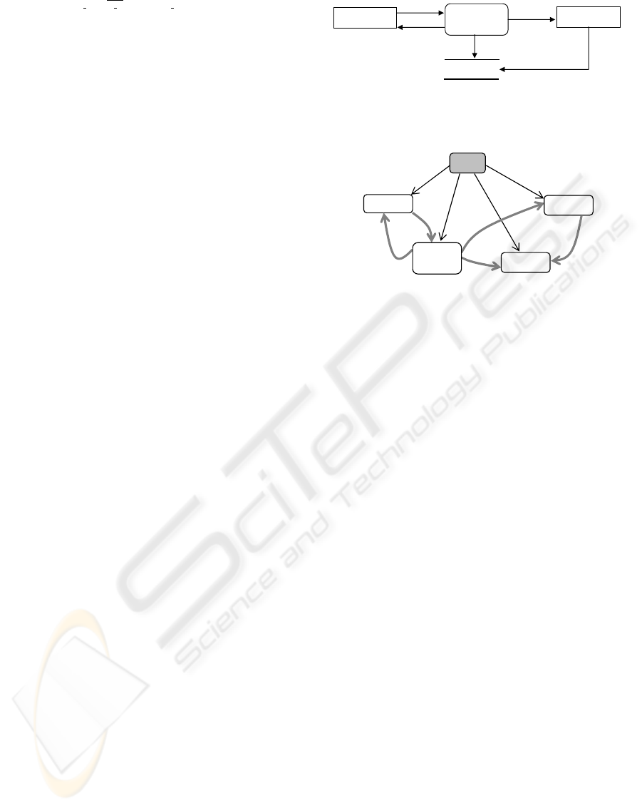
As an example, let us consider the data flow dia-
gram depicted in Figure 7 which violates the property
that Data Stores can only be read or written by Pro-
cesses. Such constraint can be checked by visiting the
syntax graph of Figure 8 constructed from the DFD.
From the XPG specification the VLCC automati-
cally generates a visual environment for data flow di-
agrams.
CUSTOMER
KITCHEN
FOOD
ORDER
customer order
receipt
RECEIPT
food order
food order receipt
order receipt
Figure 7: A data flow diagram with a data flow from an
entity to a data store.
ROOT
Custome
r
kitchen
Food
Order
receip
t
Figure 8: The syntax graph corresponding to the DFD in
Figure 7.
4 RELATED WORK
The development of effective modeling environments
is a costly and time-consuming activity. Thus, it is
widely recognized the need for the adoption of suit-
able and powerful tools supporting their implementa-
tion. In the last decades, several tools have been pro-
posed, which differ in several aspects. We can clas-
sify such tools into two broad classes, named “meta-
modeling tools” and “formal-based tools”.
Systems falling in the first class are characterized
by the use of a specification model, named meta-
model, to define the visual language. In this cate-
gory can be count systems such as MetaEdit+ (Kelly
et al., 1996), Kogge (Ebert et al., 1997), ATOM
3
(de Lara and Vangheluwe, 2002). The most used
meta-modeling techniques are usually classified into
the following three main categories: ER-based, OO-
based or graph based. The choice of the meta-model
language is critic, since if it is too simple then it can
be not sufficient to specify sophisticated languages;
on the other hand, if it is too complicated then it
can be very difficult to model a new visual language.
However, meta-modeling languages do not possess
precisely defined syntax and semantic, and cannot
be used for verifying certain properties of the lan-
guage under construction. For that reason, the meta-
modeling techniques are usually supplemented with
more formal languages, such as OCL, Z notation, etc.
MetaEdit+ uses as meta-model GOPRR (Graph, Ob-
jects, Properties, Relationships, Roles) that adds the
concept of graph to OPRR model. It allows the in-
tegration of concepts and rules for checking model
integrity, consistency, and completeness by defining
ICEIS 2004 - INFORMATION SYSTEMS ANALYSIS AND SPECIFICATION
152

constraints rules. KOGGE (Ebert et al., 1997) sup-
ports the generation of visual languages such as Bon.
The meta-model used to describe the abstract syn-
tax is EER/GRAL. GRAL is used to provide integrity
conditions, which cannot be expressed by EER de-
scriptions.
Such tools do not provide adequate support for
code generation. In particular, they have ad-hoc lan-
guages able to generate simple documentation but are
not suitable to describe complicated dependencies.
On the contrary GENIE allows us to easily perform
translation by adding suitable semantic rules in order
to realize appropriate code and report generation.
An approach similar to ours has been proposed in
ATOM
3
(de Lara and Vangheluwe, 2002). It gener-
ates modeling tools by combining the use of a meta-
modeling technique and graph grammars. In partic-
ular, the ER formalism extended with constraints is
available at the meta-meta-level, where constraints
can be specified as OCL, or Python expressions.
Models are internally represented using Abstract Syn-
tax Graphs and model manipulations such as simu-
lation, optimization, transformation and code gener-
ation are expressed by means of graph grammars by
advantages of graph transformation technique.
The “formal-based tools” are characterized by the
use of a formal method for the specification of the
modeling languages. In this context, special attention
deserves systems that employ grammar formalisms
for specifying the syntax and the semantics of a vi-
sual language (Bardohl, 2002)(Chok and Marriott,
1998)(Minas, 2002)(Rubin et al., 1990)(Zhang et al.,
2001)(Uskudarli and Dinesh, 1995). This approach
allows us to exploit the well-established theoretical
background and techniques developed for string lan-
guages in the setting of visual languages. The main
differences between the existing grammar-based sys-
tems lie in the characteristics of the underlying gram-
mar formalism, its expressive power and the parsing
efficiency.
5 FINAL REMARKS
In this paper we presented a user-centered methodol-
ogy for the development of customized visual mod-
eling environments, and a tool to support it. The use
of UML meta-modeling techniques and formal meth-
ods characterizes the proposed approach. This allows
us to inherit the appealing features of both the ap-
proaches. As a matter of fact, an UML class diagram
is used during the requirements analysis in order to
provide a high-level specification of the modeling lan-
guage, which allows us to describe the entities of the
problem domain, so that they are more understand-
able by language users. Moreover, a visual editor
is automatically generated from the specified meta-
model. Note that the use of UML meta-model for
the specification of visual languages is gaining inter-
est in recent years. As a matter of fact, a meta-model
approach is underlying most generators of diagram-
matic editors. As an example, Metabuilder (Ferguson
et al., 2000) automatically generates an editor for a
new visual language starting from the class diagram
modeling the language. UML meta-modeling has also
been exploited to characterize families of diagram-
matic languages through an abstract syntax given as
a class diagram and a set of constraints in a logical
language.
The specified UML meta-models are translated into
formal specifications (in XPG format) that also in-
clude constraints on the modeling languages. Thus,
due to the use of this grammar formalism the sys-
tem exhibits several advantages. In particular, it al-
lows us to extend the ’compiler-compiler’ approach
widely adopted for the generation of programming
workbenches to visual oriented workbenches. More-
over, it allows us to easily perform several tasks on the
defined language such as customization and modifica-
tions as well as the maintenance and the debug. Suit-
able semantic rules can be defined to realize appro-
priate code and report generation, as well as to real-
ize static verification of the languages. The language
specification can be notably simplified by the adop-
tion of an incremental approach supported by context-
free style grammars. Furthermore, the approach sup-
ports the software reuse through a central repository.
Another interesting characteristic of the visual en-
vironments generated by GENIE is the use of GXL
format as data representation of the sentences. This
feature makes easier the interoperability of the envi-
ronments with other tools. As a matter of fact, some
groups from industry and research committed to pro-
vide facilities to import and export GXL documents to
their tools (Winter et al., 2002). However, the choice
of GXL does not prevent from the use of other XML-
based languages for import/export facilities. For ex-
ample, for UML visual environments, we may need
to represent the sentence also with the XMI format
(XMI, 2003).
Now, several remarkable future researches can be
foreseen. The proposed meta-model/grammar ap-
proach is based on a semi-automatic transformation
of a meta-model into the corresponding XPG specifi-
cation. As a consequence, it could be interesting to
further investigate such an aspect in order to obtain a
more automatic transformation mechanism. Finally,
we intend to carry out usability studies of the pro-
posed meta-model/grammar approach for generating
visual modeling environments.
A USER-CENTERED METHODOLOGY TO GENERATE VISUAL MODELING ENVIRONMENTS
153

REFERENCES
Aho, A., Sethi, R., and Ullman, J. (1985). Compilers, prin-
ciples, techniques and tools. Addison-Wesley.
Bardohl, R. (2002). A visual environment for visual
languages. Science of Computer Programming,
44(2):181–203.
Chok, S. and Marriott, K. (1998). Automatic Construc-
tion of Intelligent Diagram Editors. In Proceedings of
the ACM Symposium on User Interface Software and
Technology UIST98, pages 185–194, San Francisco,
California.
de Lara, J. and Vangheluwe, H. (2002). AToM
3
: A tool
for multi-formalism and meta-modelling. In 5th In-
ternational Conference FASE 2002, pages 174–188,
Grenoble, France.
Ebert, J., Suttenbach, R., and Uhe, I. (1997). Meta-CASE
in practice: A case for KOGGE. In Proceedings of
9th International Conference CaiSE’97, LNCS 1250,
pages 203–216, Barcelona, Spain. Springer-Verlag.
Ferguson, R., Hunter, A., and Hardy, C. (2000).
Metabuilder: The diagrammer’s diagrammer. In Pro-
ceedings Diagrams 2000, LNCS 1889, pages 407–
421, Edinburgh, Scotland, UK. Springer-Verlag.
Holt, R. C., Winter, A., and Sch
¨
urr, A. (2000). GXL: To-
ward a standard exchange format. In Proceedings of
the 7th Working Conference on Reverse Engineering
(WCRE 2000), pages 162–171, Los Alamitos. IEEE
Computer Society.
Johnson, S. (1978). YACC: Yet Another Compiler Compiler.
Bell Laboratories, Murray Hills, NJ.
Kelly, S., Lyytinen, K., and Rossi, M. (1996). MetaEdit+:
A fully configurable multi-user and multi-tool CASE
and CAME environment. In Constantopoulos, P., My-
lopoulos, J., and Vassiliou, Y., editors, Proceedings
8th International Conference CAiSE’96, LNCS 1080,
pages 1–21, Crete, Greece. Springer.
Kimura, T., Choi, J., and Mack, J. (1990). Show and Tell:
A visual programming language. In Glinert, E. P., ed-
itor, Visual Programming Environments: Paradigms
and Systems, pages 397–404. IEEE Computer Society
Press, Los Alamitos.
McIntyre, D. (1995). Design and implementation with Vam-
pire, pages 129–159. Manning Publications Co.
Minas, M. (2002). Concepts and realization of a diagram
editor generator based on hypergraph transformation.
Science of Computer Programming, 44(2):157–180.
Nokia Mobile Phones (1999). Press Release: Nokia ex-
pects increased mobile growth and raises subscriber
estimates.
Rubin, R., Walker II, J., and Golin, E. (1990). Early experi-
ence with the visual programmer’s workbench. IEEE
Transactions on Software Engineering, 16(10):1107–
1121.
Schmidt, C., Pfahler, P., and Fischer, U. K. C. (2002).
SIMtelligence Designer/J: A Visual Language to
Specify SIM Toolkit Applications. In Procs of (OOP-
SLA’02), Second Workshop on Domain Specific Visual
Languages, pages 32–39.
Uskudarli, S. and Dinesh, T. (1995). Towards a Vi-
sual Programming Environment Generator for Alge-
braic Specifications. In Procs. 11th IEEE Interna-
tional Symposium on Visual Languages, pages 234–
241, Darmstadt, Germany.
Vose, G. M. and Williams, G. (1986). LabVIEW: Labora-
tory virtual instrument engineering workbench. Byte,
pages 84–92.
Winter, A. (2002). Exchanging graphs with GXL. In
Mutzel, P., Jnger, M., and Leipert, S., editors, Graph
Drawing, LNCS 2265, pages 485–500. Springer-
Verlag.
Winter, A., Kullbach, B., and Riediger, V. (2002). An
overview of the GXL graph exchange language. In
S.Diehl, editor, Software Visualization, LNCS 2269,
pages 324–336. Springer-Verlag.
XMI (2003). OMG document formal/03-05-02.
Zhang, K., Zhang, D., and Cao, J. (2001). Design, con-
struction, and application of a generic visual language
generation environment. IEEE Transactions on Soft-
ware Engineering, 27(4):289–307.
ICEIS 2004 - INFORMATION SYSTEMS ANALYSIS AND SPECIFICATION
154
