
Fault-based Testing of E-Commerce Applications
Marisa A. S´anchez
1
, Juan Carlos Augusto
2
, and Miguel Felder
3
1
Dpto. de Cs. de la Administraci´on, Universidad Nacional del Sur, Argentina
2
School of Computing and Mathematics, University of Ulster at Jordanstown, UK
3
Pragma Consultores, Buenos Aires, Argentina
Abstract. Because of their complexity, business transactions are prone
to failure in many ways. This paper reports on our experience using a
fault-based testing approach. The approach overcomes the limitations of
specification-based approaches that derive from the intrinsic incomplete-
ness of the specification, and from the focus of specifications on correct
behaviors, rather than potential faults, and hence provides a complemen-
tary technique during the testing phase.
1 Introduction
Because of their complexity, business transactions are prone to failure in many
ways. For example, a request that is satisfied under normal conditions can be
unexpectedly rejected. That can be experienced in daily life when a Web server
is not available because it is busy; when we cannot properly fill in an order form
because we are not able to view information on a low resolution screen; or when
we abandon a page because it makes heavy use of cookies and we have turned
on alerts every time a cookie is activated. However, systems are normally built
considering the normal and expected pattern of behavior. Thus, a fault-based
testing approach that considers the way the system behavior can be compromised
b y failures or abnormal conditions or interactions is desirable. Testing is fault-
based when its motivation is to demonstrate the absence of pre-specified faults.
Although there are many proposals of fault-based testing [1, 2], all are con-
cerned with syntactic errors (e.g., errors in the use of relational or arithmetic
operators, incorrect variable references, etcetera). These types of errors repre-
sen t only a small portion of possible errors. In real applications, faults depend
on a multiplicity of causal factors including technical, human and institutional
aspects. This fact motivates our interest to perform a fault-based testing that is
not restricted to syntactic errors.
The work presented in [3] extends the scope of traditional fault-based ap-
proaches to semantic errors. This approach propose to characterize possible be-
haviors and rank them according to some criteria. Fault Tree Analysis is used
to determine how an undesirable state (failure state) can occur in the system
[4]. Then Fault Tree Analysis results are in tegrated with the specification of the
A. Sánchez M., Carlos Augusto J. and Felder M. (2004).
Fault-based Testing of E-Commerce Applications.
In Proceedings of the 2nd International Workshop on Verification and Validation of Enterprise Information Systems, pages 66-71
DOI: 10.5220/0002660800660071
Copyright
c
SciTePress
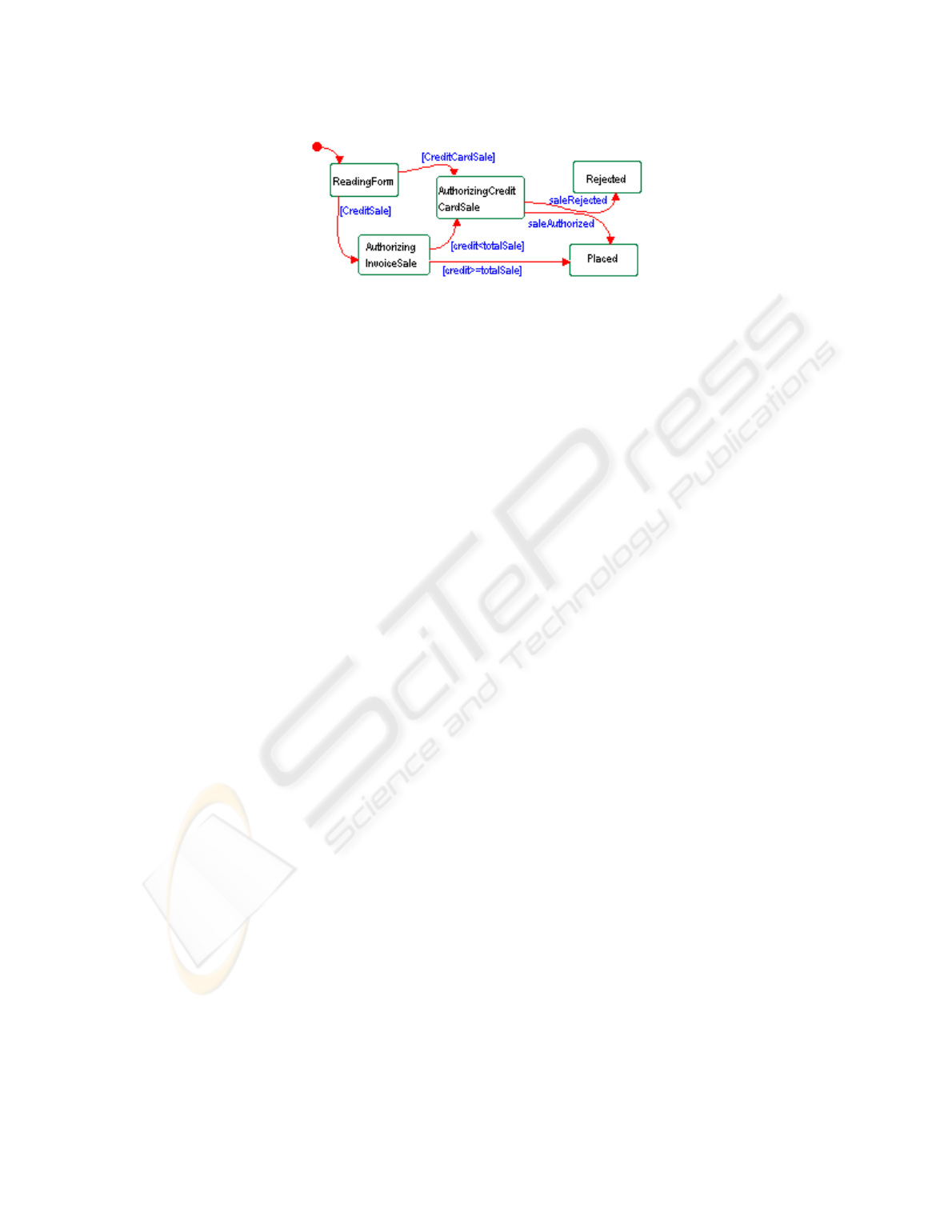
Fig. 1. Statechart for class Order
desired behavior for the system using statecharts [5]. As a result, we obtain a
testing model that provides a representation of the wa y the system behavior
can be compromised by failures or abnormal conditions or in teractions. The in-
tegration is possible since the results of the analysis are expressed in terms of
Duration Calculus formulas and we can apply some conversion rules of a for-
mula to a statechart. As a result, we obtain a testing model that provides a
represen tation of the way the system behavior can be compromised by failures
or abnormal conditions. In this way, we can automatically derive fault based test
cases from the model.
The remainder of the paper is organized as follows. In Sec. 2 a case study
that we used as the basis for our work is introduced. Then in Sec. 3 we briefly
in troduce Fault Tree Analysis. Sec. 4 is devoted to illustrate the fault-based
testing approac h, and the final conclusions are pro vided in Sec. 5.
2CaseStudy
As an example of an e-commerce application consider O^ceWeb that sells o^ce
equipmen t to larger companies. For space reasons, we only include the views
of the model necessary for our purpose. Order is one of the key concepts in
the organization, and the behavior of the order is modeled in Figure 1 using a
statec hart diagram. An order has five states: ReadingForm, AuthorizingCredit-
CardSale, AuthorizingInvoiceSale, Placed, and Rejected. If an invoice sale is not
authorized because the customer has not enough credit, then he is asked to pay
using a credit card.
Additionally, it is interesting to investigate if this normal pattern of behavior
specified for the Order, can be corrupted by unexpected conditions. For example,
it is typical that when a Web application is subject to unusual levels of activity,
it may be unavailable for some time; and the applications that depend on it do
not properly handle the error. In particular, consider the scenario in which an
order is being processed and the Credit Card Verification System is not available.
It is necesary to test how the sales system behaves under this condition.
3 Fault Tree Analysis
Fault Tree Analysis (FTA) is a widely used technique in industrial developments,
and allows to describe how individual component failures or subsystems can
67
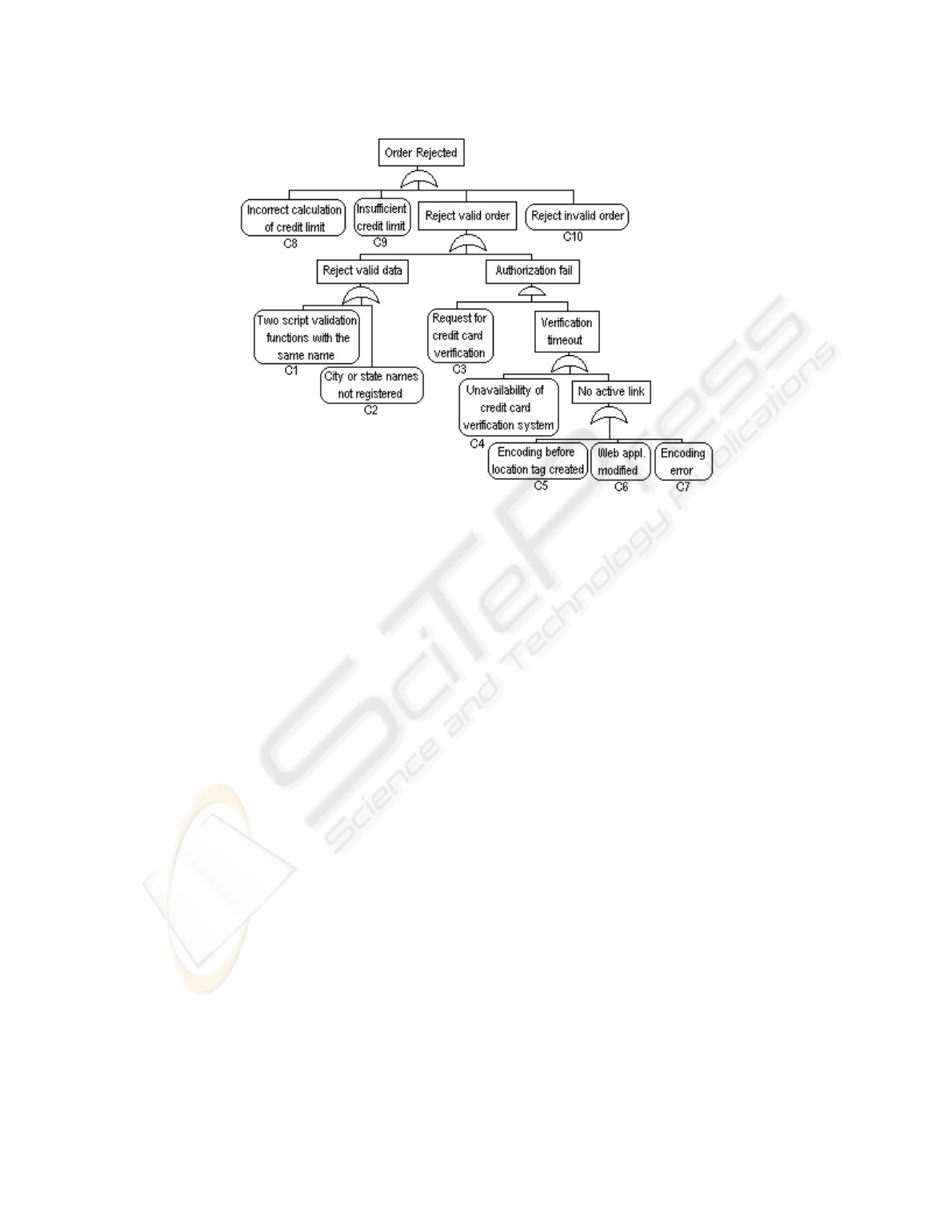
Fig. 2. Fault Tree for Order Rejected
com bine to e&ect the system behavior. The construction of a fault tree provides
a systematic method for analyzing and documenting the potential causes of
a system failure. The analyst begins with the failure scenario of interest and
decomposes the failure symptom into its possible causes. Each possible cause
is then further refined until the basic causes of the failure are understood. A
fault tree consists of the undesired top state linked to more basic events by
logic gates. Here we only consider and, or gates, as fault trees containing other
gates may be expressed in terms of these. In general, fault trees do not use the
not gate, because the inclusion of in version may lead to non-coherent fault trees,
which complicates analysis [6]. Once the tree is constructed, it can be written as a
Boolean expression and simplified to show the specific combinations of identified
basic events su^cient to cause the undesired top state. The sets of basic events
that will cause the root event are regarded as Minimal Cut Sets. The Minimal
Cut Set representation of a tree corresponds to an or gate with all the minimal
cut sets as descendants.
As an illustration of the use of FTA, consider O^ceWeb order system and
a fault tree for the hazard Order Rejected in Figure 2. For reasons of space, we
do not include a full description of nodes C8, C9 and C10. There are 9 cut sets:
{C8}, {C9}, {C10}, {C1}, {C2}, {C3,C4}, {C3,C5}, {C3,C6} and {C3,C7}.
3.1 Fault tree semantics
In [7] fault trees have been given a formal semantics based on a real-time interval
logic, the Duration Calculus (DC) [8]. In DC a system is modeled by a number
of functions from a temporal structure isomorphic to R
+
to a set of Boolean
68

values. These functions are called the state variables of the system. For a state
variable (or a Boolean combination of state variables) P ,itsdurationinatime
in terval, written
$
P in DC, is the integral of P over the time interval.
The semantics of a fault tree is determined by the semantics of the leaves, the
edges, and the gates, such that the semantics of intermediate nodes are given
by the seman tics of the leaves, edges, and gates in the subtrees in which the
in termediate nodes are roots. A leaf node is interpreted as a formula that may
betheoccurrenceofastateP , i.e.{P Q; the occurrence of a transition to state P ,
i.e. {¬P Q; {P Q; a threshold of some duration, i.e.
$
P 8. For example, in Figure
2, the basic event C8(
“Incorrect calculation of credit limit”) may be denoted by the
formula
{CreditLimitCalcQ; {FailureCreditLimitCalcQ. CreditLimitCalc denotes
the software action to calculate the credit limit, and
FailureCreditLimitCalc
represen ts the software failure to accomplish this. The semantics of intermediate
nodes depends on the structure of the subtree. For example, the semantics of an
intermediate node connected to nodes B
1
,...,B
n
through an and gate is giv en
b y the conjunction of the semantics of B
1
, ..., B
n
.
4 Construction of the Testing Model
This section is dev oted to briefly describe the overall testing framework. Given a
fault tree, we should calculate the set of basic events (cut sets) that can conduct
to the failure state. For each cut set we construct a statechart based testing
model. Using this model, we can automatically derive test cases (see Sec. 4.3).
4.1 Duration Calculus Formulas that represent a cut set
A fault tree describes the events that contribute to an undesirable system be-
havior, and also what components participate and which responsibilities do they
have. In Sec. 3.1, we described how fault trees are interpreted as temporal for-
mulas. Thus, we can interpret each cut set as a DC formula. For example, for
the cut set {C3,C4} (
“Request for credit card verification” and “Unavailability of
credit card verification system”) we provide the following DC formula:
c
1
def
= {RequestCCVQ; {CCVSUnavailableQ; {OrderRejectedQ
The form ula denotes (a) the occurrence of a request for credit card verifica-
tion (
RequestCCV), (b) the unavailability of the credit card verification system
(
CCVSUnavailable), and (c) the rejection of the order (OrderRejected).
Give n a cut set that contains n basic events CS
i
= {e
1
,e
2
, ..., e
n
}, the formula
that describes it has the form:
cs
i
def
= f
1
+ f
2
+ ... + f
n
,whereeachf
i
represents
the basic event e
i
,for1 i n, and it refers to a single component. That
is, we should include each f
i
in the specification statechart of the appropriate
componen t. For reasons of space, we consider a small example, and thus we
cannot exploit the expressive potential of DC. However, note that the formal
semantics for the graphic representation of fault trees makes statements in the
leaves precise. This precision is necessary to perform an adequate integration of
these results with the specification statecharts.
69
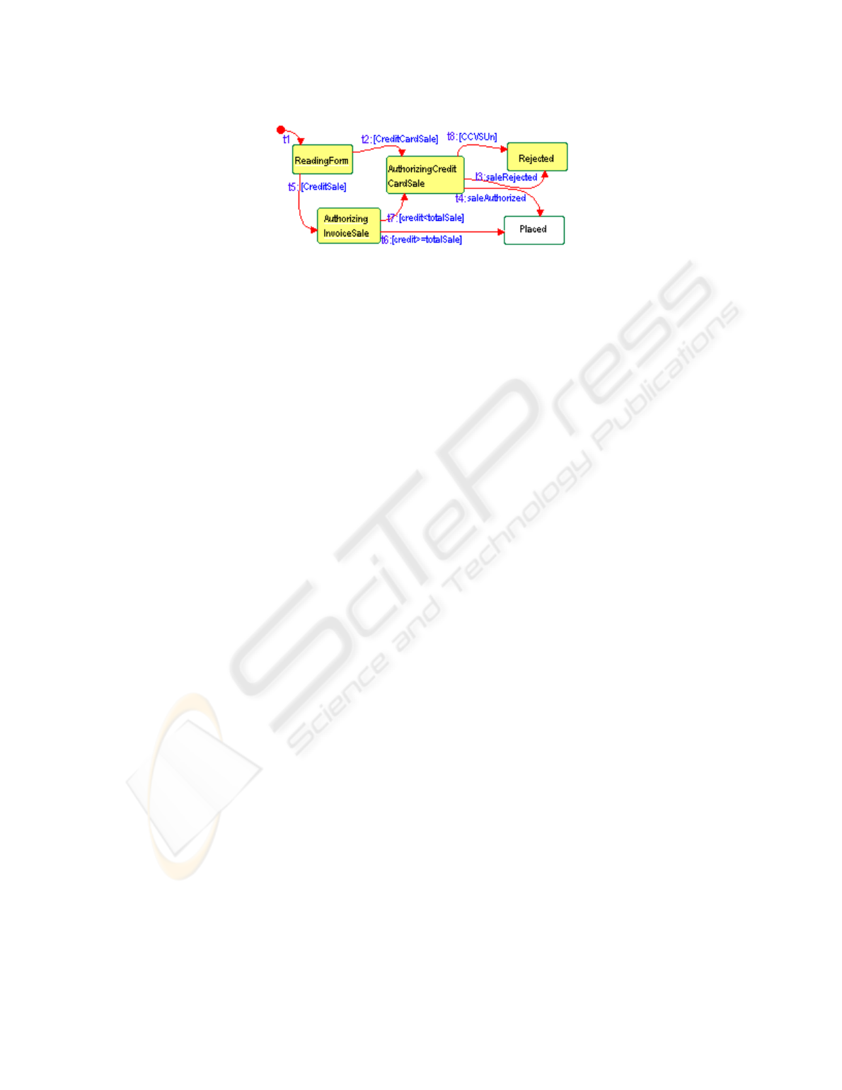
Fig. 3. Slice based on cut set { C3, C4 }
4.2 In tegration
In [3], we presented the conversion rules of a formula to a statechart. The rules
are applied to the syntactic categories of Duration Calculus formulas. As an
example, consider the cut set {C3,C4}, which is described with the formula
{RequestCCVQ; {CCVSUnavailableQ; {OrderRejectedQ. The components RequestCCV
and OrderRejected refer to the statechart’s states AuthorizingCreditCardSale
and Rejected, respectively.
RequestCCV is an action taken in state Authorizing-
CreditCardSale. Then, the form ula denotes a transition from state Authorizing-
CreditCardSale to state Rejected, and the transition is triggered by condition
CCVSUnavailable (represented by [CCVSUn] in the statechart).
Finally, we obtain the statechart of Figure 3 as a system model with respect
to cut set {C3,C4}. In order to obtain a testing model based on this scenario,
we do not need to include the whole product of the proposed statechart. We
calculate a slice using the slicing technique described in [9]. The slice includes
the shaded states and transitions t
1
,t
2
,t
8
,t
5
,t
7
(see Figure 3). Note that in any
non trivial model, the benefits of reducing the model become apparent.
4.3 Test sequence definition
In [10] the authors describe how to generate test cases based on Unified Mod-
eling Language (UML) state diagrams [11]. These diagrams are based on State-
charts. We consider their approach to generate test cases for statec harts. Then,
using a state coverage criteria we obtain the following test sequences: S
1
:(Read-
ingForm, t2, AuthorizingCreditCardSale,t8, Rejected) (conditions [Credit Card-
Sale], [CCVSUn] should evaluate to true); and S
2
: (ReadingForm, t5, Autho-
rizingIn voiceSale, t7, AuthorizingCreditCardSale, t8, Rejected) (conditions [Cred-
itSale], [credit < total sale], [CCVSUn] should evaluate to true to exercise the
test cases.
5Conclusions
This work reports on our experience using a fault-based testing approach to a
business application. The approach has been previously proposed for another
application domain (control systems) [3], and in this work we illustrate its usel-
fullness for an e-commerce system.
70

In business applications, faults depend on a multiplicity of causal factors,
and this approach allows to consider combinations of faults. We use Fault Tree
Analysis to determine how an undesirable state can occur in the system. The
results of this analysis expressed in terms of DC are integrated with the sys-
tem specified behavior to determine how we can reproduce such behaviors. If
the Fault Tree Analysis is complete, then the testing approach assures that all
conditions that enable a fault situation will show up as test cases.
Still, our experiments show that most of the scenarios resulting from Fault
Tree Analysis would be better integrated with models of the processes rather
than with statecharts. In business models, statecharts are used to represent in-
dividual resource behavior [12]. Activity (or process) diagrams show the control
and data flow of processes, and thus involve the interaction among di&erent
resources and products. Interesting fault conditions arise when individual com-
ponents can combine to a&ect the system behavior, and this information is closer
to a process description. One direction for further work is to describe how to
in tegrate fault tree analysis results with process models.
The combination of Fault Tree Analysis and statecharts, poses a problem,
such as the integration of heterogeneous specifications. Most of the tasks in-
volved, i.e. the conversion of Duration Calculus formulas to statec harts, the slic-
ing and the generation of test sequences can be automated. Much of the ongoing
work is directed at developing tool support.
References
1. Special issue on Fault-Based Testing. IEEE Trans. on Software Eng., 6(3), 1980.
2. L. J. Morell. A Theory of Fault-Based Testing. IEEE Trans. on Software Eng.,
16(8):844—857, 1990.
3. M. A. Sanchez and M. A. Felder. A Systematic Approach to Generate Test Cases
based on Faults. In ASSE2003, ISSN 1666 1087, Buenos Aires, 2003.
4. Fault Tree Handbook. Nureg-0492, U.S. Nuclear Regulatory Commission, 1981.
5. D. Harel. Statechar ts: A visual formalism for complex systems. Science of Com-
puter Programming, 8:231—274, 1987.
6. J. B. Dugan and S. A. Doyle. Incorporating imperfect coverage into a BDD solution
of a combinatorial model. Journal of Automatic Control Production Systems,
30(8):1073—1086, 1996.
7. K.M.Hansen,A.P.Ravn,andV.Stavridou. FromSafetyAnalysistoSoftware
Requirements. IEEE Trans. on Software Eng., 24(7):573—584, July 1998.
8. Ch. Zhou, C.A.R. Hoare, and A. P. Ravn. A Calculus of Durations. Information
Processing Letters, 40(5):269—276, Dec. 1991.
9. M. A. Sanchez and M. A. Felder. Slicing of Statecharts. In ASSE2001, Buenos
Aires, pages 177—190, 2001.
10. Y. Kim, H. Hong, D. Bae, and S. Cha. Test cases generation from UML state
diagrams. In IEE Proceedings: Software, 146(4), pages 187—192, 1999.
11. G. Booch, J. Rumbauch, and I. Jacobson. The Unified Modeling Language. User
Guide. Addison Wesley Longman, Reading, MA, USA, 1998.
12. H-E. Eriksson and M. Penker. Business Modeling with UML Business Patterns at
Work. Wiley Computer Publishing. John Wiley & Sons, Inc., 2000.
71
