
Broadcast Algorithms for Mobile Ad hoc Networks
based on Depth-first Traversal
Koushik Sinha
1, ?
and Pradip K Srimani
2
1
Department of Computer Science, University of Arizona, Tucson, AZ 85721
2
Department of Computer Science, Clemson University, Clemson, SC 29634
Abstract. Two deterministic broadcast algorithms are presented for mobile ad
hoc networks where the mobile nodes possess collision detection capabilities.
The first algorithm, based on a depth-first traversal of the nodes, accomplishes
broadcast in O(n log n) time in the worst case. The second algorithm is mobility
resilient even when the topology changes very frequently, with O(∆·n log n+n·
|M|) time to broadcast in the worst case, where |M | is the length of the message
to be broadcasted and ∆ is the maximum node degree.
1 Introduction
The simplest broadcast algorithm in an ad hoc network is round-robin, which works
in O(nD) time steps, where n is the total number of nodes in the network and D
represents the diameter of the network [2]. There exists a wide range of both determin-
istic and randomized algorithms in the literature [1]- [8], [10], [11] for broadcast in ad
hoc networks. Most of these research works on designing protocols for broadcast in
ad hoc networks focus on the scenario where the nodes do not possess collision detec-
tion capabilities. With the rapid advances in technology, mobile terminals with collision
detection capabilities will soon become common in the near future.
In this paper, we present two deterministic algorithms for broadcast in ad hoc net-
works based on the collision detection capability of the mobile terminals. Our first
algorithm is suitable for networks where topologies change infrequently and it takes
O(n log n) time in the worst case. This algorithm is based on a depth-first traversal of
the corresponding graph for the ad hoc network such that collisions are detected and
eventually avoided. Compared to the algorithm in [2], the worst-case performance of
our proposed algorithm is better for high values of node degree ∆ and diameter D. For
example, with n = 1024, ∆ = 15, h = 3, and D = 40, our algorithm will need 22,528
steps in the worst-case, while that in [2] will always take 2,30,400 steps. We have also
simulated our algorithm on randomly generated networks to show that on an average,
this algorithm always takes significantly lesser time than the worst-case situation. We
then propose a second algorithm which is an extended version of the first so that it
works correctly even when the topology changes very frequently. This algorithm needs
O(∆ · n log n + n · |M|) time in the worst case, |M | being the message length. The
higher broadcast time is the price we need to pay to ensure that all nodes receive the
?
Address for Correspondence: Koushik Sinha, Department of Computer Science, University of
Arizona, Tucson, AZ 85721. Email: koushik@cs.arizona.edu
Sinha K. and K Srimani P. (2004).
Broadcast Algorithms for Mobile Ad hoc Networks based on Depth-first Traversal.
In Proceedings of the 3rd International Workshop on Wireless Information Systems, pages 170-177
DOI: 10.5220/0002662401700177
Copyright
c
SciTePress

broadcasted message even in frequently changing networks. We show that the perfor-
mance of this algorithm is better than that in [2] for short messages and high values of
∆ and diameter D.
2 System Model
A radio network is defined as a directed graph with n vertices that represent mobile
terminals. Each node is assigned a unique identifier from the set {1, 2, . . . , n}. If the
exact value of n is not known, then we can apply the technique described in [5] to
find an upper bound on the node id within a factor of 2. In the broadcast problem,
one node is distinguished as the source node (also termed as the root), which wants
to broadcast a message M. We assume that all the nodes in the network are reachable
from the source node. By the open neighborhood N(i) of a node i, we would mean
all nodes within the communication range of i. N[i] = N(i) ∪ {i}, will be termed
as the closed neighborhood of i. Every node has two modes of operation - a receiving
mode, in which it can receive message(s) from its neighbor(s) and a transmitting mode,
in which the node can transmit a message. There is a single channel over which all
the nodes in the system transmit. Time is assumed to be slotted and all transmissions
are edge-triggered, that is, they take place at slot boundaries. In a time slot, a station
can transmit and/or listen to the channel. We assume that the mobile terminals possess
collision detection capabilities. The status of the channel as seen by a node i in a time
slot is either of the three possible states :
1. N : indicating null, i.e., if no station in the neighborhood of i, or node i is transmit-
ting in the current time slot.
2. S : indicating single, i.e., if exactly one station in the closed neighborhood of i
transmitted at time t.
3. C : indicating collision, i.e., if two or more stations in the closed neighborhood of i
transmitted in the current time slot.
3 Protocol Description
A node is said to be eligible if it is yet to transmit M. For a given node i, we say an
adjacent node j is privileged if it is an eligible neighbor of i, with the largest id. We say
node i is a predecessor of node j if j is the privileged neighbor of node i.
3.1 Functions used
Function find
next
max
id(i) : This function finds the privileged neighbor of a node
i. All node id’s are assumed to be of the same length, consisting of dlog ne bits. Below,
we first describe the steps executed by this function.
Step 1 : Node i transmits a control message requesting all its eligible neighbors
with 1 in the most significant bit (msb) position of their id to respond with an acknowl-
edgement in the next time slot. Three possible cases can arise:
171

Case 1 : No node responds to the request (channel status N ), meaning thereby that
there are no eligible neighbors of node i with the msb of their id set to 1. So it transmits
a message asking all its eligible neighbors with the bits 01 in their msb and (msb - 1)
th
bit positions respectively, to respond in the next time slot.
Case 2 : An acknowledgement is received (channel status S), which implies that
there is exactly one eligible neighbor with its msb address bit set to 1. Then in the next
time slot, i transmits a message asking only j to begin broadcasting M but all other
neighbors to remain silent (no transmission).
Case 3 : Node i detects a collision (channel status C), which implies that there are
more than one eligible neighbor with the msb of their id set to 1. Then i transmits a
message asking all its eligible neighbors with the bits 11 in their msb and (msb - 1) bit
position respectively to respond in the next time slot.
Step 2 : Repeat step 1 dlog ne times, with the high order address bits set according
to the responses received in the previous k − 1 iterations of step 1, ( 1 ≤ k ≤ dlog ne),
and the (dlog ne − k + 1)
th
address bit (from the msb side) set to 1.
If for k = dlog ne, no response (channel status = N ) is received with all of previous
address bits sets to 0, then there is no eligible neighbor of node i, and the function
returns control to its predecessor node. Thus, after a maximum of 2dlog ne time slots,
node i knows its privileged neighbor, which then begins transmission of M.
Function is
neighbor
present(i) : Node i transmits a signal requesting all its eligi-
ble neighbors to send an acknowledgement signal in the next time slot. If the status of
the channel in the next time slot is S or C, then the function is
neighbor
present returns
true, otherwise it returns false.
3.2 Control Signals
transfer
control(i, j) : If the numeric value of the dlog je high order address bits of
a neighbor of i is equal to j, then that node becomes the privileged node and receives
permission from i to begin broadcasting M through this control signal. Call it node u.
All other neighbors are requested to remain silent and node i remains silent too until it
receives a signal from u to resume searching for other eligible nodes.
send
completion
signal(j, i) : Once node j has determined that it has no more
eligible neighbors it sends a signal to node i, indicating to i that it can resume searching
for other eligible neighbors of i.
3.3 Algorithm determinstic
broadcast
Algorithm determinstic
broadcast
/* Initiation of broadcasting of message M by root */
var root : integer; /* initiator of the broadcast */
begin
deterministic
broadcast(0, root, root, M);
/* The first parameter in the above call to deterministic
broadcast refers to the predecessor
of the third parameter */
/* 0 indicates that the node root has no predecessor */
end.
172

Procedure deterministic
broadcast(pred, root, i, M)
var neighbor
present : boolean;
var j : integer;
begin
transmit message M;
neighbor
present = false;
do
if (is
neighbor
present(i) = true) then
begin
/* get the highest id neighbor of i that has not yet transmitted M, i.e., the privileged node */
j ← find
next
max
id(i);
if j > 0 then /* valid node id’s are in the range 1 ≤ id ≤ n */
begin
neighbor
present = true;
transfer
control(i, j); /* permission to broadcast is granted to node j */
/* wait until j signals that it has no more eligible neighbors */
wait for a send
completion
signal(j, i) message;
endif;
else neighbor
present = false;
endif;
while (neighbor
present = true);
if (i 6= root) then /* predecessor of i can resume find
next
max
id function */
send
completion
signal(i, pred);
else end broadcasting. /* all nodes in the network have received M */
end.
The algorithm deterministic
broadcast generates a depth-first-search traversal of
the graph, with the generated depth-first-search (DFS) tree rooted at the source node.
At every step, the largest id neighbor of the currently privileged node, that is yet to
transmit the message M is selected which then broadcasts M and in turn, selects its
privileged neighbor. The process continues until all nodes in the system get a chance to
broadcast M.
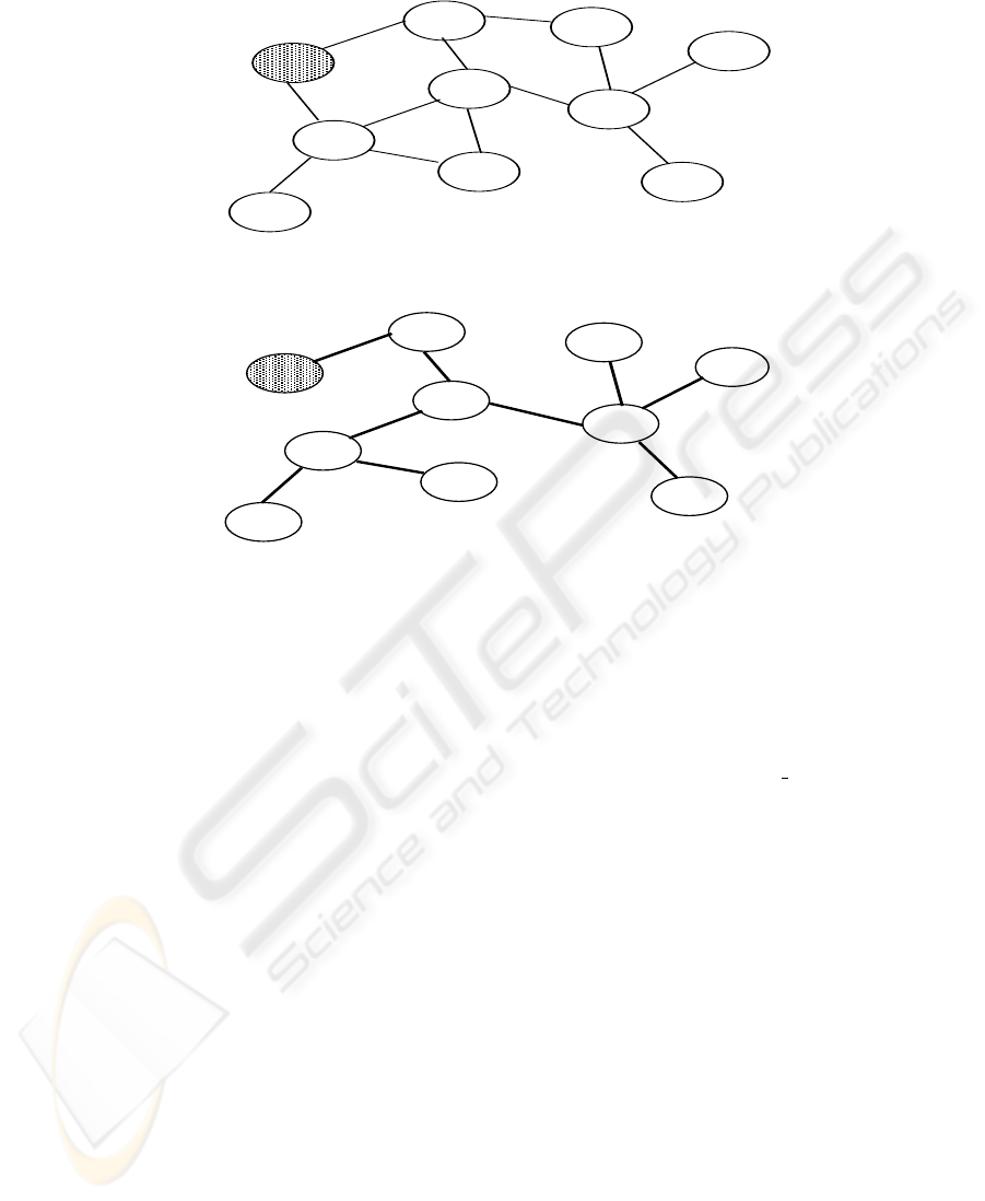
Example 1. Consider the graph shown in Fig. 1.Node 0010 initiates the broadcast pro-
cess by transmitting the message M. The depth-first-search (DFS) tree traversal gen-
erated by the deterministic
broadcast algorithm for this graph is shown in Fig. 2. The
numbers in bold beside the edges represent the order in which the nodes are processed,
and the figures in parentheses indicate the corresponding number of slots needed.
To prove that the proposed protocol is correct, we show that all nodes receive the
message M and the protocol terminates after a finite, deterministic number of steps.
Lemma 1. For any node i, if there exists at least one neighbor of i that has not yet
transmitted M, then during the execution of find
next
max
id(i), in at least one of the
dlog ne time slots, the channel status will be S.
Proof : Omitted due to brevity. For details, the reader is referred to [12].
Corollary 1. Function find
next
max
id will always return the highest id neighbor of
node i that has not yet transmitted M, if there exists any.
173
0010
1110
0011
1010
0111
0001
1011
1001
0110
0101
Fig. 1. A graph with 10 mobile terminals; Node 0010 wants to broadcast a message
0010
1110
0011
1010
0111
0001
1011
1001
0110
0101
1 2
3
4
5
6
7
8
9
(4)
(4)
(2)
(2)
(4)
(8)
(2)
(4)
(6)
Fig. 2. DFS tree generated from the above graph and rooted at node 0010
Lemma 2. All transmissions of message M by any node in the system, are free of col-
lision.
Proof : Follows directly from Corollary 1.
Lemma 3. The construction of the DFS tree by the algorithm deterministic
broadcast
requires 2ndlog ne − 2n + 2 transmission slots.
Proof : Omitted due to brevity. For details, the reader is referred to [12].
Theorem 1. The total number of slots required by the proposed broadcast protocol in
the worst case is 2ndlog ne + 2n.
Proof : Follows directly from Lemma 3 and the additional slots required for the
actual transmission of the message and the control signals.
The deterministic broadcast algorithm in [2], which is based on the model of no
collision detection capabilities of the nodes, needs O(D2
h
log
h
n) time steps, where
h is the minimum integer in the range 1 ≤ h < log n, satisfying the inequality
∆ ≤ 2
h+1
− 1. It then follows that our proposed algorithm will require lesser number
of steps if roughly, n < (D∆/4) log
h−1
n. For example, with n = 1024, ∆ = 15, h =
3, and D = 40, our algorithm will need 22,528 steps in the worst-case, while that in [2]
will always take 2,30,400 steps. In the next section, our simulation results show that the
average-case performance of our algorithm is significantly better than the worst case.
174

4 Simulation
For the purpose of evaluating the average case performance of our protocol on random
topologies, we have used the network graph model in [9] to generate random graphs
with a given value of n and three parameters α, β and γ. Larger values of α result in
more geographically spread out networks, smaller values of β result in higher diameter
networks, and larger values of γ result in smaller average node degree. For further
details, the reader is referred to [12]. The simulation results show that irrespective of
the α, β and γ values used to generate the graph, the number of transmission slots
required on an average to broadcast a message, is always much lower than 2ndlog ne,
for graphs of all sizes. A comparison between the required slots in the average case and
the worst case situation is depicted in Table 1 for graphs with 200 nodes for different
values of α, β and γ.
α
β
γ
Average Case required slots
Worst Case required slots
1.0
1.0
0.5
1573
3600
1.0
0.5
0.5
2210
3600
0.5
1.0
0.5
2505
3600
0.5
0.5
0.5
2385
3600
Table 1. Number of transmission slots required for different graphs, consisting of 200 nodes
5 Deterministic Broadcast in Highly Mobile Networks
In this section, we present a modified version of the algorithm deterministic
broadcast
which will be mobility resilient even when the topology changes very rapidly. The O(n)
algorithm presented by Chlebus et. al. in [4] for deterministic broadcast in symmetric
graphs under collision detection model would fail under some typical situation. For ex-
ample, suppose a node u was initially at a distance 2 from the source node s at the
start of the broadcast by the algorithm in [4]. Now suppose, all neighbors of s have
correctly received the message and none of them have transmitted the message yet. If
at this instance, node u, before it receives the broadcast message correctly from any of
neighbors of s, moves, such that it now has s as its only neighbor, then it will never
receive the broadcasted message. Our objective in this section is to develop a determin-
istic broadcast algorithm that would work even under such movements of the nodes.
The algorithm proceeds in four phases as described below.
5.1 Algorithm deterministic
broadcast2
Phase 1 : It consists of D transmission rounds, each consisting of a single time slot. In
round 0, s transmits a single bit control message, to indicate that it wishes to broadcast
a message M . In round i, for i > 0, all nodes at distance i from s retransmit the control
175

message simultaneously. After D rounds all nodes have either heard a collision or the
control message. In either case they prepare for the broadcast.
Phase 2 : Each node i that becomes the privileged node, transmits the message M
in the first time slot after it becomes active as the privileged node in the network. i
then builds its current list of eligible neighbors by repeatedly executing the function
find
next
max
id. (Call it the neighbor
list of node i. The order of the nodes in the
neighbor
list will be the order in which the eligible neighbors of node i will transmit.)
Node i then transmits the neighbor
list and in the subsequent time slot, the first node
in the list begins execution of the proc
phase2 procedure as outlined below.
The j
t
h node in the neighbor
list of node i will begin executing proc
phase2 if
it hears a transfer
control signal from i. However, because of the mobility of nodes,
a node j in the neighbor
list of i may not receive the transfer
control signal from
i if either i) i is no longer within its transmission range, or ii) i was not within the
transmission range of some earlier node u in the neighbor
list of i, 1 ≤ u < j In such
a situation, there will be a timeout period of 2∆dlog ne + 2n time slots, after which
phase 3 of our algorithm would initiate in order to take appropriate measures so that all
nodes receive the message. For the detailed steps in phase 2, the reader is referred to
[12].
Phase 3 : It starts after phase 2, which ends when all neighbors of the source node
have transmitted or a timeout occurs. s can identify a timeout by two ways : either
i) it hears a send
completion
signal from the last node in its neighbor
list, or ii)
2∆dlog ne + 2n time slots have leapsed since it initiated the broadcast. In round 0
of phase 3, the source node s transmits another control message indicating the end of
phase 2. In round i, all nodes at a distance i from the source simultaneously retransmit
the control message. After D rounds all nodes in the system will be aware that phase 2
has ended.
Phase 4 : It starts in the round following the end of phase 3. In its first time slot, all
nodes that are yet to receive M transmit a control message. Suppose u is such a node.
Then in the next time slots, all neighbors of u who have the message M execute the
following steps :
Suppose (m
1
, . . . , m
r
) is the binary representation of the message M . Then the
steps are divided into r stages, b
1
, b
2
, . . . , b
r
, each consisting of two time slots. In each
stage, the neighboring nodes of u that have the message M are active and all others
are silent. The active nodes transmit the source message according to the scheme
described below while the silent nodes act as receivers. The transmission in a stage b
i
,
for 1 ≤ i ≤ r is as follows : If m
i
= 0, active nodes act as receivers in the first slot
of stage b
i
and act as transmitters in the second slot of this stage. If m
i
= 1, active
nodes act as transmitters in the first slot and as receivers in the second slot. When u
hears either a S and/or C in one of the two slots of a stage, it knows that the message
transmission has ended.
The above steps of phase 4 are executed repeatedly, at most n times, until all nodes
have received the message M.
Theorem 2. Algorithm deterministic
broadcast2 accomplishes acknowledged radio broad-
casting in time O(∆ · n log n + n · |M|).
176

Proof : Phases 1 and 3 each requires D time slots. Phase 2 will end up after a
maximum of timeout slots. Phase 4 requires at most O(n ·|M|) time. Hence the proof.
Comparing again with the performance of the broadcast algorithm in [2] based on
the model of no collision detection capability, we can see that, for |M| = 1, our algo-
rithm will perform better if n < (D/4) log
h−1
n, i.e., for very high values D and ∆.
For example, with n = 1024, ∆ = 15, h = 3, and D = 60, our algorithm will need, for
|M| = 1, 2∆ · n log n + 4n slots = 3,11,296 slots, while the algorithm in [2] will need
3,45,600 slots.
6 Conclusion
We have presented two deterministic algorithms for broadcast in ad hoc networks where
the mobile terminals have collision detection capability. The first algorithm, based on
depth-first traversal, is suitable for networks where topologies change infrequently. The
second one is an extension of this first to take care of high mobility of nodes. Both these
algorithms perform better than that in [2] for short messages, high ∆ and diameter D.
References
1. R. Bar-Yehuda, O. Goldreich and A. Itai, “On the time-complexity of broadcast in multi-hop
radio networks : an exponential gap between determinism and randomization”, J. computer
and System Sci., Vol. 45, pp. 104-126, Aug. 1992.
2. S. Basagni, D. Bruschi and I. Chlamtac, “A mobility transparent deterministic broadcast
mechanism for ad hoc networks”, IEEE Trans. Networking, Vol. 7, pp. 799-807, Dec. 1999.
3. I. Chlamtac and O. Weinstein, “The wave expansion approach to broadcasting in multihop
radio networks”, IEEE Trans. Communications, Vol. 39, pp. 426-433, March 1999.
4. B. Chlebus, L. Gasieniec, A. Gibbons, A. Pelc and W. Rytter, “Deterministic broadcasting in
unknown radio networks”, Proc. of SODA 2000, pp. 861-870, 2000.
5. M. Chrobak, L. Gasieniec and W. Rytter, “Fast broadcasting and gossiping in radio net-
works”, Proc. 41st IEEE Symp. Found. of Computer Science (FOCS’2000), pp. 575-581,
2000
6. A. E. F. Clementi, A. Monti and R. Silvestri, “Distributed multi-broadcast in unknown radio
networks”, Proc. 20th ACM Symp. on Principles of Distributed Computing (PODC’2001),
pp. 255-263, 2001.
7. A. E. F. Clementi, A. Monti and R. Silvestri, “Selective families, superimposed codes, and
broadcasting in unknown radio networks”, Proc. 12th ACM-SIAM Symp. on Discrete Algo-
rithms (SODA’2001), pp. 709-718, 2001.
8. I. Gaber and Y. Mansour, “Broadcast in radio networks”, Proc. 6th Annual ACM-SIAM Symp.
Discrete Algorithms, pp. 577-585, 1995.
9. S. K. S. Gupta and P. K. Srimani, “ Adaptive core selection and migration method for multi-
cast routing in mobile ad hoc networks”, IEEE Trans. Parallel and Distributed Systems, pp.
27-38, January 2003.
10. E. Kushilevitz and Y. Mansour, “An Ω(D log n/D) lower bound for broadcast in radio
networks”, SIAM J. Computing, Vol. 27, pp. 707-712, June 1998.
11. K. Nakano and S. Olariu, “Randomized Initialization Protocols for Ad-hoc Networks”, IEEE
Trans. Parallel and Distributed Systems, Vol. 11, pp. 749-759, 2000.
12. K. Sinha, “Deterministic Broadcast and Gossiping in Ad hoc Networks”, MS Thesis, Clem-
son University, South Carolina, USA, August 2003.
177
