
A Dual-Formalism Approach to Checking Consistency
of Class and State Diagrams in UML
W. L. Yeung
Department of Information Systems, Lingnan University, Hong Kong
Abstract. The B Abstract Machine Notation (AMN) and the notation of Com-
municating Sequential Processes (CSP) have previously been applied to formalise
the UML class and state diagrams, respectively. The paper discusses their inte-
grated use in checking the consistency between the two UML diagrams based on
some recent results of research in integrated formal methods. Through a small in-
formation system example, the paper illustrates a clear-cut separation of concerns
in employing the two formal methods. Of particular interest is the treatment of
recursive calls within a single class of objects.
1 Introduction
The Unified Modeling Language (UML) [13] has emerged as an industrial standard for
documentingrequirements, specifications, designs, and implementations of information
systems. UML supports not only the fundamental object-oriented concepts including
objects, classes, methods, and inheritance, but also several contemporary approaches
to information systems development: use case and interaction diagrams have their ori-
gins in the scenario-based approach [8]; state diagrams are closely related to Harel’s
statecharts [6] for reactive systems; class diagrams are based on the entity-relationship
approach. While the integration of different approaches is still very much a subject of
on-going research, the syntax and semantics of UML have also attracted a great deal
of attention and debate. The meta-model of UML specifies rules on the composition of
each kind of diagram as well as correspondences among diagrams of different kinds.
Engels et al. [4] refer to these as well-formedness rules. Given a set of well-formed
UML diagrams about the same software, there are various ways to validate their mean-
ings individually as well as collectively. For instance, state and interaction diagrams can
be validated by animation [9].
An important way of validation involves checking logical consistency: given two
UML diagrams of different kinds, any logical statements asserted in one diagram must
not be contradicted by the other diagram, and vice versa. For instance, if a class diagram
says a book cannot be on loan and reserved by the same person at the same time, the
behaviour of a person must not be said to the contrary in a state diagram. While such
kind of analysis is facilitated by the intuitiveness of UML diagrams to a certain extent,
it can be much more rigorously carried out with the help of formal logic provided that
we can put the meanings of these diagrams in a formal theoretical setting. This would
involve formalising the semantics of UML.
L. Yeung W. (2004).
A Dual-Formalism Approach to Checking Consistency of Class and State Diagrams in UML.
In Proceedings of the 2nd International Workshop on Verification and Validation of Enterprise Information Systems, pages 2-9
DOI: 10.5220/0002664300020009
Copyright
c
SciTePress

Various ways of formalising different parts (subsets) of UML have been proposed.
In most cases, a single formalism is employed for capturing the semantics of UML.
However, different kinds of UML diagram involve disparate sets of concepts and mean-
ings that can be more naturally and conveniently expressed in different formalisms. For
example, a process algebra such as Communicating Sequential Processes (CSP) [7] or
LOTOS, is arguably more suitable than a state-based formalism, such as the B Ab-
stract Machine Notation (AMN) [1] or the Z Notation, for formalising the meaning of a
UML behavioural diagram (e.g. a state diagram). On the other hand, B and Z are more
convenient for capturing the meaning of a UML class diagram.
Integrated formal methods are currently an active research area. In particular, there
has been much interest in integrating state-based and event-based (behavioural) formal
methods [3]. This paper discusses the application of some recent results of research in
integrated formal methods by Treharne and Schneider [18,15] for checking the logical
consistency between class and state diagrams. While CSP and B have separately been
applied for similar purposes, their integratedapplication discussed in this paper is novel.
Furthermore, previous attempts (e.g. [12,11]) to capture the UML behavioural seman-
tics in B did not handle recursive calls within a class. Tenzer and Stevens [17] proposed
the modelling of objects that receive recursive calls as recursive state machines but did
not address the consistency between the class and state models. The integrated use of
CSP and B here allows us to tackle recursive calls within a class in a natural manner.
The next section defines the consistency problem addressed in this paper with a mo-
tivating example. Section 3 briefly describes the application of the B AMN to formal-
ising the class model. Section 4 illustrates the use of a single CSP control-loop process
to describe the state-machine behaviour of a system of interacting objects. Section 5
highlights the role of abstract machine operations in relating state-machine behaviour
to class structure. Section 6 outlines the application of Treharne and Schneider’s for-
mal technique for checking the consistency between state-machine behaviour and class
structure. Section 7 gives the conclusion and identifies some further work.
Flight
CarHire
flydrive
0..1
0..1
connect
0..1
0..1
xor
Fig.1. A class diagram
2 A Motivating Example
As a motivating example, let us consider a small information system that handles travel
bookings. There are two classes of objects, namely, Flight and Car Hire. Figure 1 shows
a UML class diagram for the system. A passenger’s itinerary may consist of several
connecting flights and the system maintains one booking for each flight in such an
3
itinerary; hence, there is the “connect” association among flight bookings. The system
also maintains car hire bookings for flight passengers hiring cars at their destination
airports. Since a passenger may “fly” and then “drive” away from the destination airport
in the same itinerary, there is a “flydrive” association between the two classes. Note that
a flight booking can be associated with either another flight (in a connect association)
or a car hire (in a flydrive association) but not both at the same time.
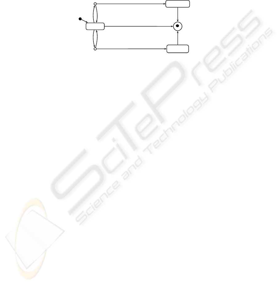
Booked
Connected
Flydriven
connect(ff)
[ff is valid]/next:=ff/return “ok”
[else]/return “no”
cancel()/next.cancel()
cancel()
flydrive(cc)
[cc is valid]/car:=cc/return “ok”
[else]/return “no”
cancel()/car.cancel()
Fig.2. A state diagram for Flight Booking objects
We can determine the functionality of a system by considering how the system is
to be used, ie. use cases of the system. Each use case may be elaborated by one or
more scenarios of interaction between the actor(s) and the system’s objects as well as
interaction among the objects. Actors and objects interact by sending call messages to
each other. The actual receipt of a (operation) call message by an object is termed a “call
event” and the desired sequences of call events happening to an object can be modelled
by a state machine and represented by a state diagram in UML. Figure 2 shows a state
diagram for individual Flight objects.
If the state machine of an object involves any actions that affect the object’s asso-
ciations with other objects, it needs to be checked against the class structure; if it also
involve transitions that are conditional upon the machine-states of other objects of the
same class, then the combined state-machine behaviour of the whole class of objects
should be checked against the class structure. More generally, since objects of different
classes may interact by sending call messages to each other, the combined behaviour of
the classes of objects involved need to be checked against the class structure.
3 Class Structuring in B
The B-Method is a formal method for developing software based on a single uniform
notation known as Abstract Machine Notation (AMN) [1,14]. Using the B-Method, a
system is modelled as an abstract machine consisting of some state variables and some
operations on the state variables. Following Lano [10], a class of objects can be mod-
elled as a single abstract machine that carries a set with elements identifying the (cur-
rently) existing objects and a number of functions corresponding to the class attributes.
The following abstract machines model the Flight and Car Hire classes as shown in
Figure 1:
4

MACHINE FlightAM
USES CarHireAM
SETS FLIGHTSET
VARIABLES flight
next car
INVARIANT flight
FLIGHTSET
next flight flight next id flight
car flight carhire dom next dom car
INITIALISATION
flight
next car
OPERATIONS
END
MACHINE CarHireAM
SETS CARHIRESET
VARIABLES carhire
INVARIANT carhire
CARHIRESET
INITIALISATION carhire
OPERATIONS
END
The “connect” association is represented by a partial injective function next from
the flight set to itself, ie. a flight can be a connecting flight of at most one another flight
and not every flight has a connecting flight. We have further stipulated that a flight
cannot be a connecting flight of itself directly or indirectly via some intermediate con-
necting flight(s), ie. next
id flight , which cannot be expressed in the UML class
diagram. Note that next
is the non-reflexive transitive closure of next. The “flydrive”
association is represented by another partial injective function car. The operations of
the above abstract machines will be considered in Section 5.
4 Behavioural Modelling in CSP
A UML state diagram describes the state-machine behaviour of an object in terms of
states, events, and transitions, as well as any actions that accompany the transitions. We
may extract from a state diagram the desired sequences of call events happening to an
object and describe them by a CSP process. For the discussion in this paper, we ignore
other kinds of events such as change events and we use the following simplified syntax
of CSP (for the time being):
P a P c x E x P d v E v P P P P P
x E x
P if b then P else P S p
where a is a synchronisation event and can be in compound forms such as a i, c and
d are communication channels for inputs and outputs, respectively, x represents input
variables, v represents output values, E
x is a predicate on x, b is a boolean expression,
and S
p refers to a process expression parameterised by expression p. The process
a
P first engages in event a and then behaves as P. The process c x E x P
is prepared to input a value along channel c into variable x provided that E x is true
and then behaves as P. The process d
v E v P is prepared to output any value v
for E
v is true along channel d and then behaves as P. P P is a process that is
prepared to engage in one of the initial events of either P
or P ; once an initial event
of P
i
(i 1 or 2) chosen by the environment has happened, it behaves as P
i
afterwards.
P
P is a process that may choose to behave as either P or P but the choice is
nondeterministic.
x E x
P is the indexed nondeterministic choice in which P may take
any value x such that E
x is true. The if expressionmakes the choice between P and P
depending on the boolean expression b in the usual way. Finally, S p is a process name
with a parameter expression p; we can define a process with the name S p recursively
by mentioning its own name S
p (where p is an expression for the parameter p)in
its definition. The following CSP process describes the desired sequences of events
5
happening to a Flight object according to the state diagram in Figure 2 :
Flight new Booked
Booked
cancel Stop connect Booked Connected flydrive Booked Flydriven
Connected cancel Stop
Flydriven
cancel Stop
We can model a state machine more precisely in CSP by taking into account any input
parameters and actions associated with individualevents.Furthermore, we can use a sin-
gle “control-loop” process to describe the state-machine behaviour of a whole class of
objects, provided that we give up any concurrency among them. The following process
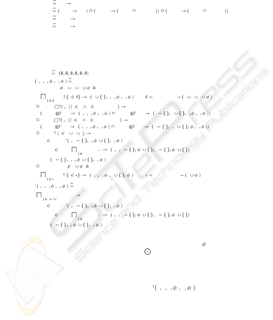
models the desired sequences of events and actions for the whole system of objects:
SystemSM S
S b c f
f
h
c
FLIGHTSET b c f
f
i i
new
f
i i S b i c f
f
h
c
where FLIGHTSET b c f
f
connect
c
i x i b x FLIGHTSET
connect “no” S b c f
f
h
c
connect “ok” S b i c i f
f
h
c
flydrive
c
i y i b y CARHIRESET
flydrive “no” S b c f
f
h
c
flydrive “ok” S b i c f i
f
h
c
cancel
f
i i b c f
if i c then S b c i f
f
i h
c
else if i f then
j j h
cancel
c
j S b c f i
f
i h j
c
j
else S b i c f
f
i h
c
CARHIRESET h
c
i i
new
c
i i S b c f
f
h i
c
where CARHIRESET h
c
S b c f
f
h
c
j j b c f
cancel
f
j
if j c then S b c j f
f
j h
c
else if j f then
j j h
cancel
c
j S b c f j
f
j h j
c
j
else S b j c
f
j h
c
In order to keep track of the machine-state of each individual object, the SystemSM
process carries six sets of object identities: the first four sets b, c, f, and
f
correspond to
the Booked, Connected, Flydriven, and Final (
) states of Flight objects, respectively;
the last two sets are for CarHire objects. The body of SystemSM offers a choice of all
call events for the system except the internal cancel
c
event for Car Hire objects. Note
that we have used subscripts f and c (for Flight and Car Hire, respectively)to resolve the
name clashes among parameters and events as in cancel
f
and cancel
c
. Recursivecancel
f
calls for connected Flight objects are handled by S b c f
f
h
c
. On the other hand,
cancelling a “flydriven” flight results in a cancel
c
which models the sending of a call
from the flydriven Flight object to the associated Car Hire object, whose identity is
nondeterministic because the control-loop process does not maintain information about
associations between the two classes of objects.
6
5 Abstract Machine Operations
The information for resolving the nondeterministic choices in SystemSM is actually
available from the abstract machines defined earlier in Section 3. For instance, the non-
deterministic choice following the connect event depends on the validity of the input
parameter—x is valid if it identifies an object which is in either the Booked, Connected,
or Flydriven states and connecting flight i and flight x will not lead to circular flight
connections. While the machine-state of Flight object x can be determined within the
control-loop process itself, information about flight connections can only be obtained
from FlightAM through operations such as the following one:
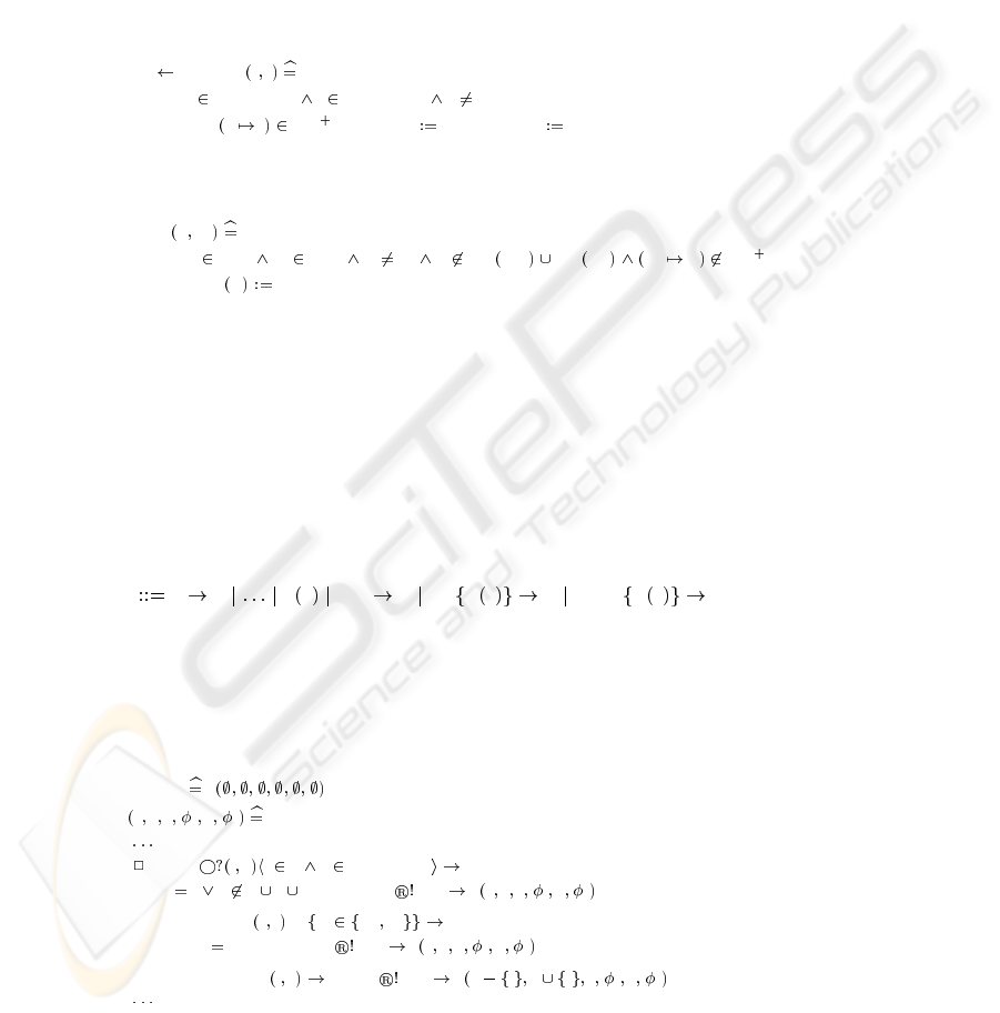
reply connected x i
PRE x FLIGHTSET i FLIGHTSET x i
THEN IF
x i next THEN reply yes ELSE reply no END END
On the other hand, whenever a Flight object successfully changes its state from Booked
to Connected, the following operation should be executed to update the abstract ma-
chine:
connect ff gg
PRE ff flight gg flight ff gg ff dom next dom car gg ff next
THEN next ff gg END
6 Checking Consistency
To check the consistency between a CSP control-loop process and its corresponding
B abstract machine, we can make use of Treharne and Schneider’s coupling between
CSP and B [18, 15]. Here we only illustrate the application of their coupling with our
example. For a detailed account of the coupling itself, the reader is referred to [18,15].
We first need to incorporate the calling of appropriate abstract machine operations
into the control-loop process. This requires an extended version of CSP as given in [15]
as follows:
P a P S p e?v P e!x E x P e?v!x E x P
The last three additional options of the syntax are used for “calling” abstract machine
operations with either input (
?) parameters, output (!) parameters, or both, respectively,
where e is a communication channel corresponding to an abstract machine operation.
Notice that the emphasised symbols “
?” and “!” are reserved for abstract machine oper-
ation calls. We can now elaborate the control-loop process SystemSM with appropriate
abstract machine operation calls as shown partially below:
SystemSM S
S b c f
f
h
c
connect
c
i x i b x FLIGHTSET
if x i x b c f then connect “no” S b c f
f
h
c
else connected? x i !rr rr yes no
if rr yes then connect “no” S b c f
f
h
c
else connect? i x connect “ok” S b i c i f
f
h
c
7
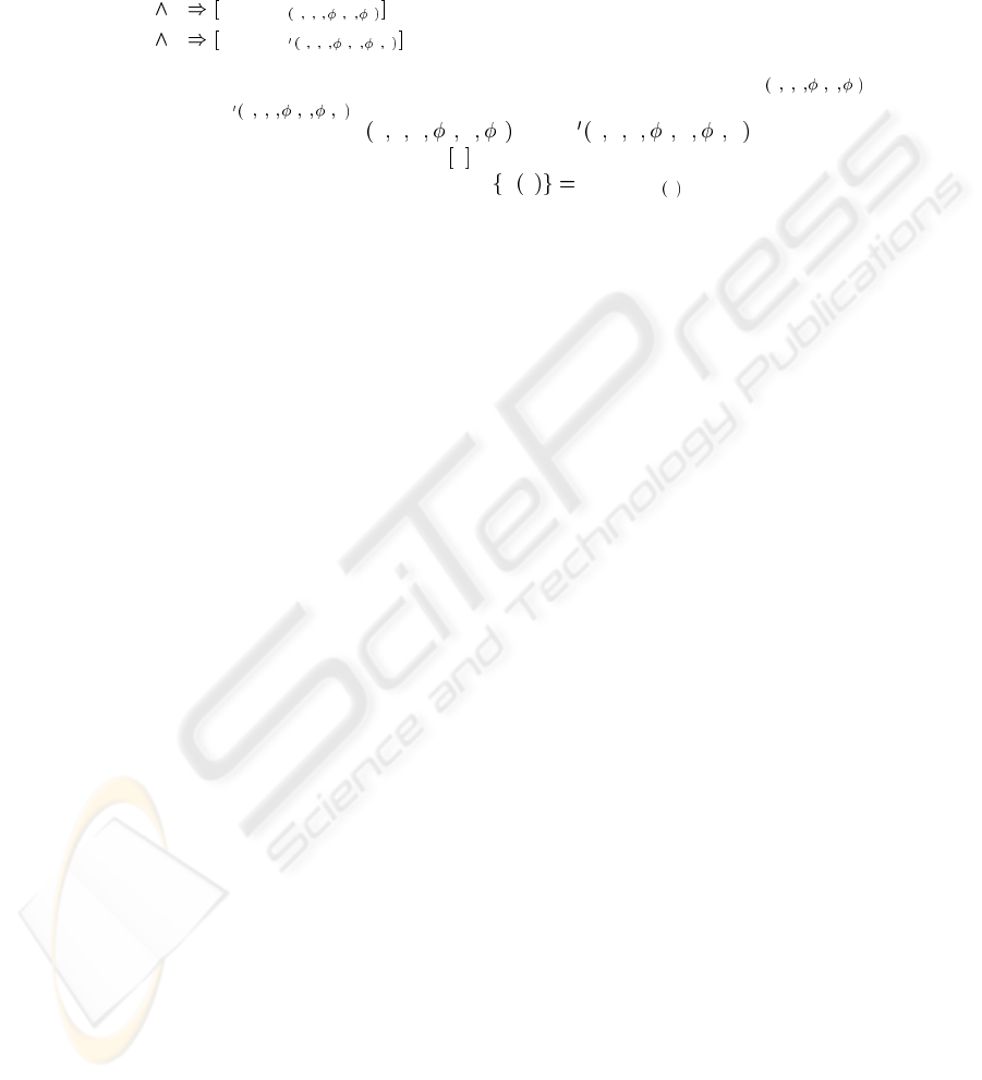
Based on Treharne and Schneider’s coupling between B and CSP [18], we can ascertain
that SystemSM only calls those abstract machine operations within their preconditions
if we can find a control loop invariant (CLI) which holds at each recursive call within
the body of SystemSM, ie.:
CLI I BBODY
S b c f
f
h
c
CLI (1)
CLI
I BBODY
S b c f
f
h
c
n
CLI (2)
where I is the invariant of the abstract machine SystemAM and BBODY
S b c f
f
h
c
,
and BBODY
S b c f
f
h
c
n
are the translation of the CSP expressions used in defining
the parameterised process S
b c f
f
h
c
, and S b c f
f
h
c
n , respectively,
into B AMN operations. The notation
S P denotes the weakest precondition for opera-
tion S to achieve P. The translation function
S p BBODY
S p
is defined inductively
based on the extended syntax of CSP. The proof of (1) and (2) can be found in [19].
7 Conclusion and Further Work
This paper has presented an example of applying of a pair of integrated formal methods,
namely B and CSP, to the checking of consistency between the class model and state
model of UML. The integrated approach allows the two formal methods to be applied
separately and efficiently, with the help of support tools, to the two UML models: the B-
Methods is supported by the B-Toolkit [2] and AtelierB [16] whereas CSP is supported
by the FDR model checking tool [5]. Consistency between the two models can simply
be established by Treharne and Schneider’s coupling between CSP and B.
A small information system example has been used to illustrate a clear-cut sepa-
ration of concerns in employing the two formal methods: the machine-states and tran-
sitions of individual objects are maintained by a CSP control-loop process, whereas
information about their attributes and associations is kept in a B abstract machine. The
advantages include clarity and tractability in the formal descriptions. While recursive
calls cannot be modelled in B, a recursive CSP process lends itself to the modelling
of recursive calls among a class of objects. On the other hand, although the use of a
single CSP control-loop process to capture the state-machine behaviour of a system of
interacting objects rules out any concurrency among the objects, it does comply with
the run-to-completion semantics of the UML state model. The lack of concurrency is
also deemed reasonable for data-intensive enterprise information systems such as our
example.
Further work is needed to generalise the integrated approach to handle more com-
plex state machines as well as more elaborate class structures involving generalisation
and specialisation. These can be achieved by developing more realistic case studies.
Support tools for translating state diagrams into CSP are also desirable.
Acknowledgements
This work is supported by a study leave from Lingnan University, Hong Kong. The
author would like to thank Helen Treharne, Steve Schneider, and Damien Karkinsky for
their discussion and help during his visit at Royal Holloway, University of London.
8

References
1. J. R. Abrial. The B-Book. Cambridge University Press, 1996.
2. B-Core (UK) Ltd., Oxford (UK). B-Toolkit User’s Manual, Release 3.2, 1996.
3. H. Bowman and J. Derrick. A junction between state based and behavioural specification.
In P. Ciancarini, A. Fantechi, and R. Gorrieri, editors, Proceedings of 4th IFIP International
Conference on Formal Methods for Open Object-Based Distributed Systems, pages 213–237.
Kluwer, 1999.
4. Gregor Engels, Jochem M. K¨uster, Reiko Heckel, and Luuk Groenewegen. A Methodology
for Specifying and Analyzing Consistency of Object-Oriented Behavioral Models. In Pro-
ceedings of the 8th European Software Engineering Conference Held Jointly with 9th ACM
SIGSOFT Symposium on the Foundations of Software Engineering, pages 186–195. ACM
Press, 2001.
5. Formal Systems (Europe) Ltd. Failures-Divergence Refinement: FDR2 User Manual, 2003.
6. David Harel. Statecharts: A visual formalism for complex systems. Science of Computer
Programming, 8(3):231–274, June 1987.
7. C. A. R. Hoare. Communicating Sequential Processes. Prentice Hall, 1985.
8. I. Jacobson, M. Griss, P. Jonsson, and G. Oevergaard. Object-Oriented Software Engineer-
ing: A Use Case Driven Approach. Addison-Wesley, 1992.
9. Kai Koskimies, Tarja Syst¨a, Jyrki Tuomi, and Tatu M¨annist¨o. Automated Support for Mod-
eling OO Software. IEEE Software, pages 87–94, January–February 1998.
10. K. Lano. The B Language and Method: A Guide to Practical Formal Development. FACIT.
Springer-Verlag, 1996.
11. H. Ledang and J. Souqui`eres. Integrating UML and B Specification Techniques. In
GI2001 Workshop: Integrating Diagrammatic and Formal Specification Techniques, Uni-
versit¨at Wien,
¨
Osterreich, September 2001.
12. Eric Meyer and Jeanine Souqui`eres. A Systematic Approach to Transform OMT Diagrams
to a B Specification. In J. Wing, J. Woodcock, and J. Davies, editors, FM’99 – B Users Group
Meeting – Applying B in an industrial context : Tools, Lessons and Techniques, volume 1708
of LNCS, pages 875–895. Springer-Verlag, 1999.
13. Object Management Group. OMG Unified Modeling Language Specification Version 1.4,
September 2001.
14. Steve Schneider. The B-Method: An Introduction. Palgrave, 2001.
15. Steve Schneider and Helen Treharne. Communicating B Machines. In ZB’2002 – Formal
Specification and Development in Z and B, volume 2272 of Lecture Notes in Computer Sci-
ence (Springer-Verlag), pages 416–435, Grenoble, France, January 2002. Laboratoire LSR-
IMAG.
16. STERIA - Technologies de l’Information, Aix-en-Provence (F). Atelier B, Manuel Utilisa-
teur, Version 3.5, 1998.
17. J. Tenzer and P. Stevens. Modelling recursive calls with uml state diagrams. In Proceedings
of FASE 2003, volume 2621, pages 135–149. Springer, 2003.
18. Helen Treharne and Steve Schneider. Using a process algebra to control B OPERATIONS. In
IFM’99 1st International Conference on Integrated Formal Methods, pages 437–457, York,
June 1999. Springer-Verlag.
19. W. L. Yeung. Checking Consistency Between Class Structure and State Machines Based
on CSP and B. Technical report, Department of Information Systems, Lingnan University,
Hong Kong, 2003.
9
