
Communication based workflow loop formalization
using Temporal Logic of Actions (TLA)
Jos
´
e L. Caro
1
, Antonio Guevara
1
, Andr
´
es Aguayo
1
, and Jos
´
eL.Leiva
1
1
Computer Science Department, Malaga University, 29071 M
´
alaga, Spain
Abstract. The workflow map development for an organization is a highly com-
plex process. Therefore, the workflow map should be tested and validated be-
fore it is implemented (into a WfMS). Most current workflow systems deal with
this validation issue by using simulation modules that “execute” the model and
examine the possible problems before it is truly “executed” and implemented.
Although these simulation modules are very useful for the management team to
detect problems in the business processes represented by the workflow, it would
be advisable to find other more reliable methods. In this paper we propose a for-
mal method based on Temporal Logic of Actions to formalize workflow maps
(based on a communication modelling methodology).
1 Introduction
Actually there are two main research areas related to workflow technology [6]: (i) work-
flow management systems (WfMS) (the implementation of workflow technology), and
(ii) workflow modelling techniques (the capability to express the process, work, infor-
mation, methods, etc. for a organization into a specification called worklow map).
A workflow map could describe business a process at the conceptual level needed
for the evaluation, understanding and design of such business processes, as well as
capturing information process tasks at level that describes such process requirements
for information systems and human skills [2]. This model should allow and facilitate
the automated demonstration of properties. For example: will any workflow never be
executed? Will this workflow ever be executed? Is the operation carried out with a
specified time cost? Formal proving mechanisms will provide a practical solution to
these kinds of problems [3].
In this paper, our objective is to develop a language/action paradigm formalization
[5], based on a extension of temporal logic, known as Temporal Logic of Actions (TLA)
[4]. This paper is organized as follows: we begin with a brief description of workflow
(sec. 2). In section 3, the TLA elements needed for the formalization are described. In
section 4, we develop the TLA formalization of the language/action paradigm. The last
section summarizes the paper conclusions.
2 Workflow
Workflow has a wide range of possibilities related to group support and the automation
of organizational processes. In general terms we can define workflow as [9]: “workflow
L. Caro J., Guevara A., Aguayo A. and L. Leiva J. (2004).
Communication based workflow loop formalization using Temporal Logic of Actions (TLA).
In Proceedings of the 1st International Workshop on Computer Supported Activity Coordination, pages 233-238
DOI: 10.5220/0002670002330238
Copyright
c
SciTePress
is comprised by a set of activities dealing with the coordinated execution of multiple
tasks developed by different processing entities in order to reach a common objective”.
A good approach to workflow modelling techniques, that includes a formal method for
achieve demonstrations, can be found in [1, 7, 10, 6,2].
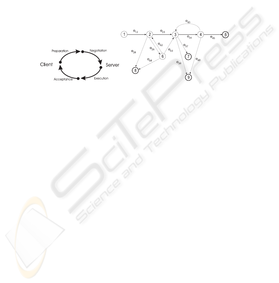
Fig.1. Workflow loop & state diagram
Communication-based methodologies stem from the “Conversation for Action” model
developed by Medina-Mora, Winograd, and Flores [5]. The communication between
client (Cli) and server (Svr) can be defined in four steps (figure 1): request/preparation,
negotiation, development and acceptance. The language/action perspective modelling
is based on the “speech-act” theory developed by John Searle [8] that has been adapted
for workflow management (statechart).
The diagram starts at state 1, opening the conversation (by Cli), that triggers the
transition to state 2, where the server Svr has three options: promise, perform the work
(state 3); refuse, closes the conversation (state 8); counteroffer, negotiation of satis-
faction terms (state 6). The simplest path is going through the following transitions:
promise, the task is accepted (from state 2 to 3); report, the accepted task is done (from
state 3 to 4); declare, the service is accepted (from 4 to 5). Other option is if Svr
initiates a counteroffer (from state 2 to 6), Cli has three options: accept, state 3; coun-
teroffer, back to state 2; decline, the service is refused (state 8). From state 3 there are
this additional options renege, not performing (from 3 to 7) and withdraw the request
(state 3 to 9). After Svr reporting that the work is concluded the possible actions are:
declare, the work has not been concluded satisfactorily and Svr has to do it again (from
state 4 to 3) and withdraw the petition (from state 4 to 9).
3 Temporal Logic of Actions
Temporal Logic of Actions (TLA) combines two logics the action logic and temporal
logic [4]. All TLA formulas are TRUE or FALSE in a behavior σ defined as a infinite
sequence of states <s
0
,s
1
,s
2
,...>.
3.1 Elements of State Logic in TLA
– Variables. The semantic of [[x]](s) is the function of the value of x in the state s.
234

– State and predicate functions. The semantics of [[f]] is a mapping of states into
values.
– Actions. We obtain [[A]](s, t), by first replacing each variable x with [[x]](s) and
each variable x
with [[x]](t) to later evaluate the expression. It is said that the state
pair (s, t) is a “A-step” iff [[A]](s,t) is TRUE.
– Active action in a state. An action A is said to be active in a state s if there is a state
t such that (s, t) is a A-step: [[Enabled A]](s)
.
= ∃t ∈ σ :[[A]](s, t).
3.2 Elements of Temporal Logic in TLA
In TLA, the system behavior is modelled as an infinite sequence of states. The basic
elements are actions and temporal logic:
– Predicates. A behavior satisfies the predicate P iff (if and only if) is satisfied in
the first state: [[P]](<s
0
,s
1
,s
2
,...>) ⇒ [[P ]](s
0
). Similarly, a behavior satisfies
the action A iff the first pair of states of the given behavior is an A-step: [[A]](<
s
0
,s
1
,s
2
,...>) ⇒ [[A]](s
0
,s
1
).
– “Always” (2) operator. Given a formula F , 2F asserts that F is always TRUE:
[[2F ]](<s
0
,s
1
,s
2
,...>)
.
= ∀n ≥ 0:[[F ]](<s
n
,s
n+1
,s
n+2
,...>).
– “Eventually” (3F ) operator. The formula 3F asserts that F is eventually TRUE:
[[3F ]](<s
0
,s
1
,s
2
,...>)
.
= ∃n ≥ 0:[[F ]](<s
n
,s
n+1
,s
n+2
,...>).
– Validity. A formulae F is valid iff it is satisfied for all behaviors ( F
.
= ∀σ ∈
S
∞
:[[F ]](σ)), where S
∞
denotes the set of all possible behaviors: F
.
= ∀σ ∈
S
∞
:[[F ]](σ).
– Specification in TLA. A formal specification has the following general formula:
Π
.
= Init ∧ 2(A
1
∨ A
2
∨ ...∨ A
n
).
– Fairness Operators. The fairness operators are in charge of ensuring that “nothing
abnormal will happen”:
• Weak fairness (WF). Asserts that an action has to be infinitely executed fre-
quently if it is continuously enabled for an infinitely long time: WF
v
(A)
.
=
23A
v
∨ 23¬EnabledA
v
.
• Strong fairness (SF). Asserts that an action has to be infinitely executed fre-
quently if it is often infinitely enabled: SF
v
(A)
.
= 23A
v
∨32¬EnabledA
v
.
– Formal system specification. A formal specification of a system, within fairness
conditions, can be represented as: Π
.
= Init ∧ 2[N]
v
∧ L.
3.3 Formal approach to state diagram modelling
∆ formula represents the statechart (equation 1).
Init
∆
.
= ∃n ∈ I : P
n
A
n
.
= ∃e ∈ E(n):ε
e
∧ P
d(e)
∆
.
= Init
∆
∧∀n ∈ N : 2[P
n
⇒A
n
]
v
(1)
Where, N : set of nodes; I: set of initial nodes; E(n): set of edges originating at
node n; d(e): destination node of edge e; P
n
: predicate labelling node n; ε
e
: action
labelling edge n.
235

4 Formalizing the language/action paradigm
In order to formalize in TLA the state diagram its edges are labelled e
ij
as shown in
figure 1. Work W
k
is a quadruple expressed in the equation W
k
.
= {I,H,P,SC,V }
where: W
k
.I: information; W
k
.H: tools and methods; W
k
.P : human, role or agent
to develop the task; W
k
.SC: terms of work satisfaction; W
k
.V : set of state variables
belonging to the workflow. The set of nodes in our diagram will be denoted by N
i
,
where i is the number of the current state (initial state N
1
). In this way, and bearing in
mind the equation to be satisfied in the initial state, we have Init
∆
.
= ∃n ∈ I : P
n
.
Therefore, to complete the definition of the initial state we have to give meaning to P
N
1
(equation 2).
P
N
1
indicates that the workflow will start when an event coming from agent A is
triggered (DetectT rigger). The agent A corresponds to the client Cli, and the event
is a request for service identified as IDWF and corresponding to the workflow. The
next state variables belonging to the set V are defined as follows (we will omit the V ):
W
k
S: work state, W
f
S: current state, W
f
P : current phase, W
k
: current work, XW
k
:
external work proposed by A, W
f
Cli: client and W
f
Svr: server. Once the workflow
has started the system transits to N
2
through edge e
12
(equation 3).
P
N
1
.
= DetectTrigger(Type, Origin, Workflow)
∧Workflow = IDWF ∧ Type ∈ T
WFID
∧ Origin = A (2)
e
12
.
= W
k
= XW
k
∧ W
f
P
=“prep.” ∧ W
f
S
=“active” ∧ W
k
S
=“study”
∧W
f
Cli
= A ∧ W
f
Svr
= SelAgent(OrgDB, B) (3)
The workflow IDWF is instantiated and the requested external work is assigned to
the execution model that includes work XW
k
, that will be assigned by the function
SelAgent(OrgDB,B) (usign the organizational knowledge database OrgDB) and the ini-
tial terms of satisfaction XW
k
.SC. In the state N
2
, the work has to be evaluated. The
petition and the result of such evaluation is resented by EvalWk(W
k
,Agent), where W
k
is the work to be evaluated W
k
. The response is obtained from CounterOffer is possi-
ble to return: “commitment”, “counteroffer” (and the consecuent new W
k
), “decline”
or “cancel” (eq. 4). From state N
2
we can advance through edges e
22
, e
26
and e
28
.
Edge e
28
leads to state N
8
, which is a final state of uncompleted termination (eq. 5).
Consequently, a predicate that will abort the execution of the workflow will be used
in N
8
. This will trigger an exception so that the system can take appropriate actions,
therefore, P
N
8
.
= Exception(IDWF, “abort”,W
k
). The function Exception triggers
the exception of aborting the task, and goes back to TRUE when completed. The edge
e
26
corresponds to a counteroffer from B after the evaluation done in P
N
2
(eq. 6).
P
N
2
.
= S = EvalWk(W
k
,B) ∧ (S =“commit.” ∨ S =“c.off.” ∨ S =“dec.”)(4)
e
28
.
= S =“decl.” ∧ W
f
P
=“prep.” ∧ W
f
S
= “abort” ∧ W
k
S
=“Svr
ab.
”(5)
e
26
.
= S =“c.offer” ∧ W
f
P
=“neg.” ∧ W
f
S
= “act.” ∧ W
k
S
=“neg.”
∧ W
k
= CounterOffer(W
k
,W
f
.Svr) (6)
236

In N
6
another evaluation is carried out by A (equation 7). We have three options:
reconsidering the offer i.e., transit to N
2
(eq. 8), refuse the offer and raise an exception
(transit to N
8
, eq. 9).
P
N
6
.
= S = EvalWk(W
k
,W
f
.Cli) ∧ (S =“ac.” ∨ S =“c.off.” ∨ S =“decl.”)(7)
e
62
.
= S =“c.off.” ∧ W
f
P
=“neg.” ∧ W
f
S
= “act.”
∧ W
k
S
=“neg.” ∧ W
k
= ConunterOffer(W
k
,W
f
.Cli) (8)
e
68
.
= S = “dec.” ∧ W
f
P
= “neg.” ∧ W
f
S
= “abort” ∧ W
k
S
=“Cli
refuses
”(9)
The third option is to accept the work W
k
and transit to N
3
(eq. 10). Similarly, if
the evaluation leads to B accepting the work, we could directly transit from N
2
to N
3
(eq. 11).
e
63
.
= S = “acc.” ∧ W
f
P
= “devel.” ∧ W
f
S
= “exec.” ∧ W
k
S
= “acc.”(10)
e
23
.
= S = “acc.” ∧ W
f
P
= “devel.” ∧ W
f
S
= “exec.” ∧ W
k
S
= “acc.”(11)
To define the semantic of P
N
3
we need the following functions: Trigger(t
i
,W
f
):
trigger t
i
to enable the sub-workflow W
f
; Completed(W
f
): TRUE if W
f
has been sat-
isfactorily completed; Aborted(W
f
): TRUE if W
f
has terminated as abort; Abort(X):
TRUE if X aborts the workflow. In P
N
3
all workflow subtasks must to be executed. The
following case has to take place: a) all subtasks a
i
have to be completed; b) the incorrect
termination of some subtasks has to be detected; or c) the client aborts the workflow.
Let W
k
.a
i
each of the subtasks comprising the task of W
k
, then P
N
3
is defined as the
equations 12 and 13:
P
N
3
.
= ∀(a
i
∈ W
k
,t
i
/t
i
= Trg(a
i
))Trigger(t
i
,W
k
.a
i
) ∧ (ExecP) (12)
ExecP
.
= 2∀a
i
∈ W
k
/Completed(W
k
.a
i
)
∨2∃a
i
∈ W
k
/Aborted(W
k
.a
i
) ∨ Abort(W
k
.Cli) (13)
At this point two options are possible: aborting the execution and transit to state N
7
or N
9
depending on who aborted or transit to evaluation state N
4
(eq. 14, 15, 16 and
17).
e
39
.
= ∃a
i
∈ W
k
/(W
k
.a
i
.W
f
S = “aborted” ∧ W
k
.a
i
.W
k
S =“Svrref. Wk”)
∧(W
f
P
=“exec.” ∧ W
f
S
= “aborted” ∧ W
k
S
=“Svr
refuses
”) (14)
e
37
.
= ∃a
i
∈ W
k
/(W
k
.a
i
.W
f
S = “aborted” ∧ W
k
.a
i
.W
k
S =“Cli
refuses
”)
∧(W
f
P
=“exec.” ∧ W
f
S
= “aborted” ∧ W
k
S
=“Cli
refuses
) (15)
e
34
.
= ∀a
i
∈ W
k
/(W
k
.a
i
.W
f
S = “accepted” ∧ W
k
.a
i
.W
k
S = “completed”)
∧(W
f
P
=“eval.” ∧ W
f
S
= “active” ∧ W
k
S
=“Cli
s
eval.
”) (16)
P
N
4
.
= EvalReport(W
k
,B)=“correct” ∨ EvalReport(W
k
,B)=“incorrect”
∨ Exception(IDWF, “abort”,W
k
) (17)
237

If the work satisfies the terms, there is a transition to successful state N
5
.Onthe
other hand, if it does not, we go back to the subtask execution state (this path is optional)
and if it is aborted, it leads to N
9
(eq. 18, 19, and 20).
e
49
.
= W
f
P
= “evaluation” ∧ W
f
S
= “aborted” ∧ W
k
S
=“Cli
rejects
” (18)
e
45
.
= W
f
P
= “complete” ∧ W
f
S
=“completed”∧ W
k
S
=“Wk
accept
”(19)
e
43
.
= W
f
P
= “execution” ∧ W
f
S
= “active” ∧ W
k
S
= “reexecute” (20)
State N
5
only has to send a completed signal: P
N
5
.
= Signal(IDWF, “WF completed”,W
k
).
Once these definitions are completed and the model equations are applied to formalize
a state diagram (eq. 1) we obtain the formal representation.
5 Conclusions
The use of formal methods based on logic in workflow modelling can establish an au-
tomated, formal, and robust reasoning mechanism that will successfully provide insight
into these issues (conflict, deadlock, reacheability, reliability and satisfability). The ap-
plication of TLA to workflow management systems provides three fundamental bases
[3]: (i) theory: providing a theory with a valid and robust basis to carry out analysis; (ii)
formalization: expressing workflow maps as TLA expressions; and (iii) analysis: pro-
viding a mechanism for the automated demonstration of workflow model properties.
References
1. W. Aalst. Workflow Verification: Finding Control-Flow Errors Using Petri-Net-Based Tech-
niques. Lecture Notes in Computer Science, 1806:161–183, 2000.
2. J. L. Caro, A. Guevara, and A. Aguayo. Workflow: a solution for the cooperative devel-
opment of an information system. Business Process Management Journal, 9(2):208–220,
2003.
3. J. L. Caro, A. Guevara, A. Aguayo, S. G
´
alvez, and A. Carrillo. A temporal reasoning ap-
proach of communication based workflow modelling. In O. Camp, J. Filipe, S. Hammoudi,
and M. Piattini, editors, ICEIS’2003. Internaciontal Conference on Enterprise Information
Systems, pages 245–250, Angers, France, 2003. Ecola Superior de Setubal, ACM, IEEE.
4. L. Lamport. Specifying Systems. Addison–Wesley, 2002.
5. R. Medina-Mora, T. Winograd, R. Flores, and F. Flores. The Action Workflow Approach
to Workflow Management Technology. In Proceedings of ACM CSCW’92 Conference
on Computer-Supported Cooperative Work, Emerging Technologies for Cooperative Work,
pages 281–288, 1992.
6. H. Reijers. Design and Control of Workflow Processes, volume LNCS-2617 of Lecture Notes
in Computer Science. Springer, 2003.
7. W. Sadiq and M. E. Orlowska. Analyzing process models using graph reduction techniques.
Information Systems, 21(2):117–134, April 2000.
8. J. R. Searle. A taxonomy of illocutionary acts. In K. Gunderson, editor, Language, Mind,
and Knowledge. Minnesota Studies in the Philosophy of Science, Vol. 7, pages 344–369.
University of Minnesota Press, Minneapolis, Minnesota, 1975.
9. A. Sheth and M. Rusinkiewicz. On transactional workflows. IEEE Data Engineering Bul-
letin, 16(2):37, June 1993.
10. H. Zhuge, T. yat Cheung, an d H. keng Pung. A timed workflow process model. Journal of
Systems and Software, 55(3):231–243, January 2001.
238
