
Towards Modeling Web Service Composition in UML
Roy Grønmo, Ida Solheim
SINTEF, Forskningsveien 1, Pb 124, Blindern N-0314 Oslo
Abstract. This paper focuses on how to model and build composite web ser-
vices from already existing services. We build on the experience in workflow
modeling and see if the principles are applicable to the web service domain. It
is revealed that there are particular needs for web services that are not fully
captured by traditional workflow modeling. UML is used as the modeling tool
for capturing these needs. If there is no direct support for the need, we propose
a UML extension. Many of the proposed extensions are shown within a com-
posite web service model that represents a gas dispersion emergency case.
1 Introduction
Web services are functional components, available over the Internet, which may
comply with a set of standards, such as HTTP, XML, SOAP, WSDL, etc. We define
a web service to be any service accessible over the Internet which takes XML as input
and produces an XML result. Furthermore a web service is composed if it reuses
existing services. The idea behind web service composition is that many sub tasks,
already defined as web services, can be used together to accomplish a larger task.
Realization of this larger task will be the resulting composite web service.
We intend to build composite web services by following OMGs principles of the
Model-Driven Architecture (MDA) [1]. In MDA one start with defining high-level
models in UML, define conversion rules from UML to a target platform, and then use
code generation to derive much of the implementation code for a desired platform.
In the area of web services research there are two main aspects that may be modeled:
the service and the workflow modeling. Service modeling identifies services to be
exposed with their interfaces and operations, while the workflow modeling identifies
the control and data flows from one service to the next.
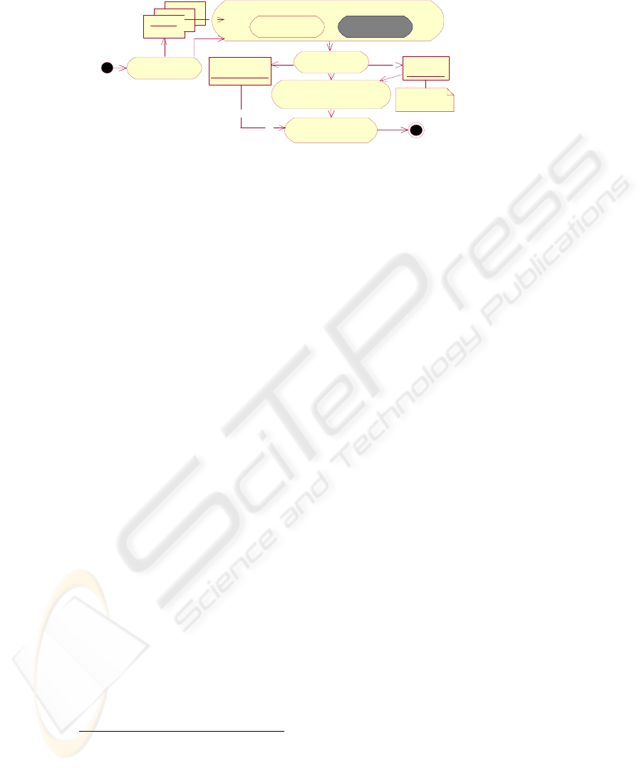
2 Actions for building a composite web service
We identify how the model-driven approach can be applied when building a compos-
ite web service (Fig. 1).
Grønmo R. and Solheim I. (2004).
Towards Modeling Web Service Composition in UML.
In Proceedings of the 2nd International Workshop on Web Services: Modeling, Architecture and Infrastructure, pages 73-86
DOI: 10.5220/0002680700730086
Copyright
c
SciTePress
Discover web
services
MODEL COMPOSITE WEB SERVICE
Workflow
modeling
Service
modeling
Workflow
modeling
Service
modeling
Publish composite
web service
CompositeWeb
Service-WSDL
WSDL
Workflow
XM L
Implement composite web
service in workflow engine
Transformation
tool
BPEL4WS,
WSCI, BPML
etc...
Fig. 1. Actions for building a composite web service
1. Discover web services. Existing web services are discovered from a web service
registry. The output of this activity is a list of web service descriptions represented
in the de-facto standard WSDL.
2. Model composite web service. This action consists of service and workflow mod-
eling. The service modeling identifies the interface of the composite web service,
and the workflow model identifies how the existing web services are reused.
Transformation rules from service models and workflow models are specified and
realized by a Transformation tool. The service model is mapped to a WSDL
document and the workflow model is mapped to a workflow XML document.
(There are a number of different workflow XML languages and there is no de-
facto standard so far [2].)
3. Implement composite web service in workflow engine. The workflow XML
document is sent to a workflow engine that produces implementation code for
handling control-flow and data-flow. This involves invocation of the reused web
services.
4. Publish composite web service. Finally the WSDL document for the composite
web service is published in a web service registry.
The focus of this paper
1
is on workflow modeling in activity 2, model composite web
service. Service modeling is not covered in this paper.
3 Workflow Modeling Applied to Web Services
Since UML is the de-facto industry standard modeling language, we choose to ex-
plore the workflow modeling with UML as the modeling language. The graphical
models and the common use of UML make it a good candidate for expressing under-
standable models. UML activity diagrams are the natural part of UML to use for
workflow modeling of web service compositions.
1
This work is funded by the European Union IST-2001-37724 project, Adaptable and Com-
posable E-commerce and Geographic Information Services (ACE-GIS)
74

Aalst [2] has gathered the results from the workflow research and identified a set of
20 patterns concerning the control-flow aspect. In this context, a pattern is defined by
Wohed et al. in [3] to be abstracted forms of recurring situations found at various
stages of software development. For several workflow XML languages and workflow
products Aalst has indicated if they have direct support for the different patterns. The
five basic control patterns are patterns supported by all languages and products. In the
following table we identify how UML
2
support these basic patterns.
Table 1. The five basic control patterns and the support in UML
pattern
name
Sequence Parallel
split
Synchro-
nization
Exclusive
choice
Simple
merge
descriptio
n
execute
activities in
sequence
execute
activities
in paral-
lel
synchro-
nize two
parallel
threads of
execution
choose one
execution
path from
many alter-
natives
merge two
alternative
execution
paths
UML Control-
Flow
Fork Join Decision-
Node
Merge
3.1 Success criteria
For the specific problem domain of composing web services we identify particular
patterns and study how these can be expressed in UML activity diagrams. We discuss
different suggestions and propose UML extensions with stereotypes and tagged Val-
ues when we do not see a satisfying solution with the basic UML activity construc-
tions. We define these success criteria for the UML modeling:
1. Expressing web service patterns. The UML constructions must be capable of
expressing the most needed patterns. The five basic control patterns must be sup-
ported. In addition, some of the other 15 control patterns defined by Aalst et al.
should be supported if there is a common need when defining workflow of web
services. Finally there may be further web service needs that are captured by
other patterns not concerning control flow.
2. Readability. The UML model shall be easy to understand for experienced mod-
elers. This means that it should be easy to see what is going on, and the diagram
should not be too cluttered.
3. Executable. The UML model shall be precise enough and contain enough details
so that a complete workflow XML document may be generated from it. We as-
sume that a workflow XML document can be used by a workflow engine and
thus be executable.
4. Independence of workflow XML language. The UML model shall be inde-
pendent of a particular workflow XML language. The motivation is that we do
not want to be tied to one language, especially when there are many competing
workflow XML language proposals.
2
The UML terminology in this paper follows UML 2.0 [4]
75

We see that the design goals are in conflict with each other. The best solution shall
thus be some kind of compromise that best suits the four design goals all together.
The next section identifies special needs for composing web services.
4 Capturing Composite Web Service Patterns
We have identified some web services workflow patterns without direct support
within traditional workflow modeling. For each pattern the paper provides:
• A description of the pattern and why this is relevant for web services.
• A concrete example illustrating the pattern.
• An optional discussion on different suggestions
• A proposed solution for supporting the pattern within a UML activity diagram
by introducing UML extensions (stereotypes and tagged values)
• An evaluation of the proposed solution against the design criteria.
4.1 Pattern: Web Service Call
Description. An action that represents a web service needs to be associated with the
operation to be called for executing the web service.
Example. An action represents an OGC conform Web Feature Service (WFS) [5]
that can deliver building features.
Proposed solution. We assume that all web services have a WSDL description. Thus
the operation may be identified by the triple: WSDL file, service name and operation
name. We define three tagged Values for this triple (WSDL, service and operation).
Furthermore we have added the possibility to provide the value of fixed parameters as
another tagged Value called fixedParameters. The value is an XML expression pro-
viding the value for one ore more parameters. The example below shows how to set
three parameters for a web service call to WFS which will deliver building features.
The WFS is a service that can deliver many types of feature instances. The third fixed
parameter specifies that TypeName=Buildings, in order to ensure that only features of
type building are provided:
<FixedParameters>
<FixedParameter name="SERVICE" value="WFS"/>
<FixedParameter name="VERSION" value="1.0.0"/>
<FixedParameter name="TypeName" value="Building"
</FixedParameters>
Evaluation. The design criteria are met. The details introduced are considered impor-
tant only to the execution of the workflow and displaying this information will usu-
ally overload the model reader with information. This is the reason why the informa-
tion is registered as tagged values that easily can be hided in UML tools, and not
within notes that are displayed in the diagram.
76
4.2 Pattern: Loop
Description. We have one or more actions that shall be repeatedly executed depend-
ing on some conditions. There are different loop constructions with minor differences
such as for-each and repeat-until. We will only look at the for-each construct in this
paper as the other loop constructs can be easily produced from this by minor changes.
Example. A customer creates orders on a web site which results in an XML docu-
ment consisting of a collection of orders of different products. For each order, we
need to update the stock, charge the customer and deliver the product. After all orders
are processed, the web application returns some shipping information.
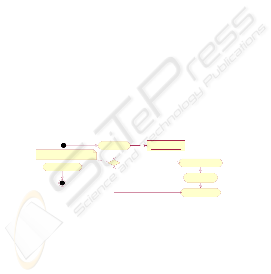
Proposed solution. We propose to use a <<ForEach>> stereotyped decisionNode that
chooses to iterate another time or exit the loop. Since we know that we are dealing
with web services we assume that all data objects are XML documents (according to
our web service definition). In such a case an XPath [6] selection may be used to
select the elements for which the loop shall iterate over. We have placed this XPath
selection within a select attribute in a <<ForEach>> stereotyped note attached to the
decisionNode (Fig. 2). The first part of the select expression follows XPath notation
by expressing a named data object with a $-prefix. This named data object must be
represented elsewhere in the model, which is the case for the order object. The flow
that continues loop iteration has a predefined guard name of [more elements] and the
exit-loop flow has a predefined guard name of [else]. The flow that exits one iteration
body to test for more iterations, has been given the name "loop". This name is op-
tional in our notation.
Evaluation. The design criteria are met. The UML 2.0 Specification [7] announces
support for a LoopNode construct. At the time of writing the notation of a LoopNode
is not published yet. The proposed solution in this paper may be replaced or enhanced
when LoopNode is released.
order :
FeatureCollection
Up date Stock
Charge
Customer
Deliver Product
<<ForEach>>
[ more elements ]
Create Orders
Return Shipping
Info
[ else ]
<<ForEach>>
select="$order/Collection//orders"
loop
Fig. 2. ForEach loop using an XPath expression to select elements
4.3 Pattern: Data Transformation
Description. In traditional workflow we may define each action with output data that
matches the input of the next action. This is not the case with web services where we
want to discover existing services provided by external parties. In such a case we
have no control over the exact input and output parameters. In general, we must al-
ways do some kind of data transformation in-between each action step. A web service
77
is defined by WSDL in such a way that there is always at most one input message and
at most one output message. There are different kinds of data transformation:
• one-to-one identical. This is the simplest case. The output of one previous action
matches exactly the wanted input of the action.
• one-to-one non-identical. The output of one previous action is used to produce
the wanted input of the action. They are not equivalent, which means some kind
of transformation is needed. It may involve extraction or copying parts of the
previous data object to the new one or it may involve a semantical mapping such
as a conversion from Fahrenheit to Celcius degrees.
• many-to-one. The input relies on more than one previous output data object. It
may involve extraction or copying parts of the previous data objects or it may in-
volve semantical mappings.
Example. One service returns the temperature in Fahrenheit degrees. The next ser-
vice to be invoked consumes temperature given in Celcius degrees.
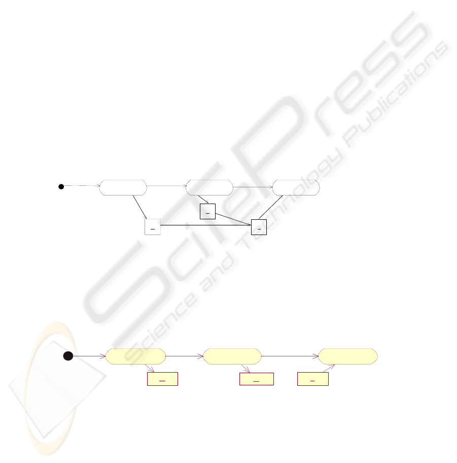
Suggestion 1 – Flows between data objects
Flows are drawn from all the previous data objects directly to the wanted input object
(Fig. 3). If we want to add further details about the actual transformation we could
add this as a transformation note to the flow. This is OK if there is only one previous
data object, but there is no way to attach the note to several flows, which would be
needed in the figure below.
A B C
p:
q:
r:
Fig. 3. Flows between data objects
Suggestion 2 – Mapping function on the flow
A mapper function is defined as a statement on the flow from the previous action to
the action with the wanted input (Fig. 4). This solution handles all the different data
transformation cases, and it may be further detailed with a transformation note at-
tached to the flow with the mapping statement.
p
A B C
q
r
/ r = map(p,q)
Fig. 4. Mapping function on the flow
Suggestion 3 – Explicit mapper actions
78
A data transformation is handled by an explicit action with the <<DataMapper>>
stereotype (Fig. 5). Details about the actual transformation are placed in a transforma-
tion note attached to the <<DataMapper>> action.
A B C
<<DataM apper>>
MapToR
<<transformation>>
r.part1 = p.part3
r.part2 = q.part2
p:
q: r:
Fig. 5. Explicit mapper actions
Proposed solution. We propose Suggestion 3 for every many-to-one transformation.
For the one-to-one identical and non-identical transformation, we leave the modeler
with the choice of either Suggestion 3 or Suggestion 1. In the simplified case of hav-
ing one-to-one identical transformation, we propose a simplified diagram where the
output of one action is sent directly to another action as input, without any data map-
per action or transformation note.
Evaluation. Suggestion 1 is not able to handle the many-to-one transformations and
is hard to interpret for a model reader. Suggestion 2 has the disadvantage that it does
not capture that the flow with mapping function has to be executed before the data
input object is created. Suggestion 1 and 2 has the advantage over Suggestion 3 in
that the diagram is not cluttered. Suggestion 2 and 3 has the advantage that they han-
dle all kinds of transformations, while Suggestion 3 is the only one that clearly shows
when there is a mapping action going on. The proposed solution of mixed approaches
minimizes diagram cluttering.
4.4 Pattern: Alternative Services
Description. When working with web services there is a great risk that a service is
not responding. The server may have trouble, there may be too many simultaneous
requests or the internet connection may be lost. Furthermore there may be a choice
based on differences with respect to performance, quality of service and pricing.
There is a need to model that there are alternative services in the workflow model that
perform the same task.
In this paper we restrict the solution to only capture that there are alternative services
and not specify any selection criteria. With this simplification we can also simplify
the behavior of the workflow engine that implements the workflow. If the workflow
engine supports concurrency, then the services may be invoked in parallel and the
first one to answer will terminate all the other ongoing threads. If the workflow en-
gine does not support concurrency, then each service is invoked in turn. If the first
79
answers within some time limit, then the remaining services are ignored, or else the
first service invocation is terminated and the next service is invoked. This will con-
tinue until one of the service invocations succeed within the time limit.
Example. At some stage in our workflow we need to book flight tickets. We have
discovered two alternative flight booking web services from different providers. The
choice among the two services is based on network availability, price of tickets,
availability of flights etc.
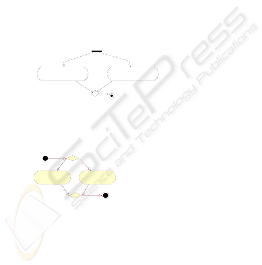
Suggestion 1 – Fork with merge
In this solution we start with a fork that has one flow to each alternative service and a
flow from each alternative service to a merge (Fig. 6). The semantics would be ex-
actly what we want, and the UML diagram is easy to understand. Many services are
invoked in parallel threads, and the merge will only wait for the first flow to finish.
<<WebService>>
ServiceA
<<WebService>>
ServiceB
Fig. 6. Fork with merge
Suggestion 2 – DecisionNode as a fork
A DecisionNode acts as a fork, which is indicated by the <<Fork>> stereotype (Fig.
7).
ServiceA
<<WebService>>
ServiceB
<<WebService>>
<<Fork>>
Fig. 7. DecisionNode as a fork
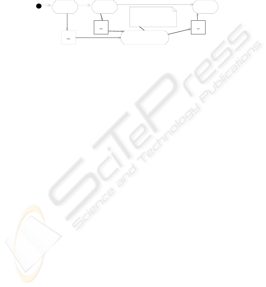
Suggestion 3 – Using empty wait action
In this solution we use two empty actions that start in parallel with the alternative
services (Fig. 8). The empty actions have no task to complete. The flow going out
from the first empty action handles initialization of the finished variable. The second
empty action is a wait action that continues when the first one of the alternative web
services has completed. This solution is inspired by the discriminator pattern and the
80
N-out-of-M-join given by Dumas et al. in [8]. This solution has modified the sugges-
tions of Dumas et al. to be more intuitive for the reader.
A
B1
<<WebService>>
B2
<<WebService>>
B1
<<WebService>>
B2
<<WebService>>
/ fini shed := true
/ finished := true
/ finished := false
C
Empty action
to initialize the "finished" variable
Empty action to wait for one of the
alternative services to complete.
[ else ]
[ finished = true ]
Fig. 8. Using empty wait action
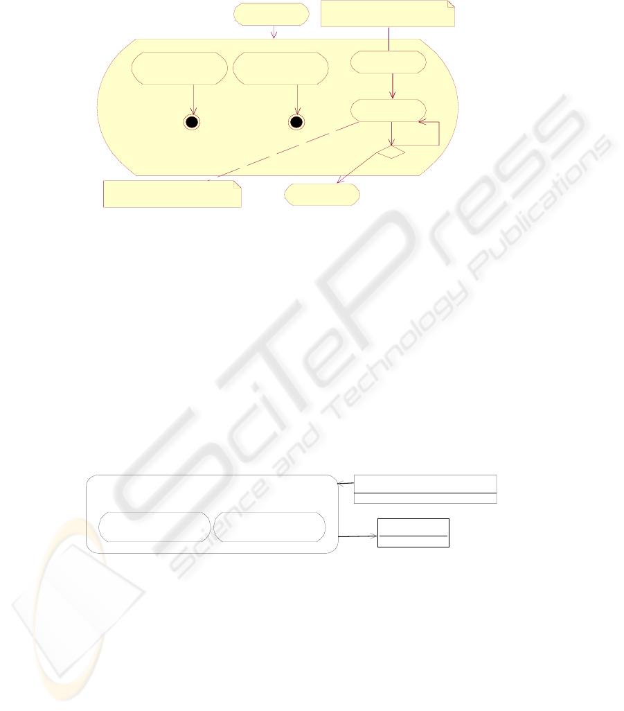
Suggestion 4 – Alternatives as sub-actions
In this solution the task is modeled as an action of its own with a specified input data
object and specified output data object (Fig. 9). The rest of the workflow only relates
to this information. The action is stereotyped as <<AlternativeServices>> to indicate
that its task may be fulfilled by a set of alternative services. The alternative services
are placed inside as sub-actions. The sub-actions may need data mappings to handle
conversions between the input and output of the <<AlternativeServices>> action and
the input and output of each sub-action. This is all modeled inside the <<Alternative-
Services>> action. The sub-actions shall be web services and thus stereotyped
<<WebService>>. The sub-actions use the name of the provider as their name since
they inherit the task name of its <<AlternativeServices>> action.
<<AlternativeServices>>
Get Nearest Airport
<<WebService>>
IONIC
<<WebService>>
e-blana
coordinates:GetPlantLocationSoapOut
airportCode:String
Fig.9. Alternatives as sub-actions
Proposed solution. We propose to use Suggestion 4.
Evaluation. Suggestion 1 is illegal in UML 1.5 since a fork always shall be followed
by a join. This is not required in UML 2.0 Specification [9] which opens up for the
suggestion. Suggestion 2 is not intuitive since it breaks a general guideline on deci-
sionNodes to have branches that are exclusive choices. The advantage of Suggestion
3 is that it is realized by concepts that are already there in UML, without having to
81

introduce extensions. The disadvantage of Suggestion 3 is that it has two additional
actions which are not really part of the workflow, but are present only to enforce our
desired need.
Suggestion 4 is a very clean and easy-to-understand model, while the semantics are
captured with the specification of the stereotype <<AlternativeServices>>. The intro-
duction of a new stereotype in Suggestion 4 gives direct modeling support for the
pattern.
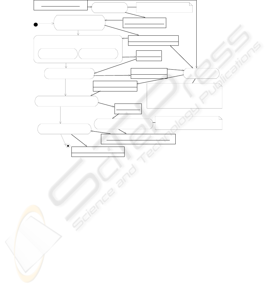
5 Gas Dispersion Emergency Case
The ACE-GIS project case "calculate gas dispersion" has been modeled using many
of the modeling patterns described in this report (Fig. 10). The model represents a
composite web service that lets a user register information about a gas leakage from a
power plant, and the final outcome is an image map displaying the gas dispersion
plume after some period of time. The web services are provided by vendors within
the ACE-GIS consortium and one vendor outside the project. Here we describe what
the model expresses by following the workflow of the actions on the left side, from
top to bottom:
1. Get Plant Location. This is a web service which needs the plant identification as
input and produces the coordinates of the plant as output. Since the input of the ac-
tivity diagram, leakageDetails, does not match the input of this step, a
<<DataMapper>> action is used which copies the plantID to the correct place in
the required input.
2. Get Nearest Airport. This is a <<AlternativeServices>> action, meaning that
there is more than one provider delivering this service. The main action takes co-
ordinates as input and returns airportCode as output. In this case there is a one-to-
one identical mapping from the output of the previous action to the input of this
action, and the simplified modeling (without data transformation action) has been
used. The realization of the <<AlternativeServices>> action can perform the two
web service calls in parallel or try one after the other. The first answer is used and
the next one is ignored. This makes the main task more reliable, as one of the two
services may be unreachable, and still we get our needed result.
3. Get Wind. This web service takes an airport code as input and returns wind in-
formation. The input of this action is directly consuming the output of the previous
action and thus the data transformation is one-to-one identical.
4. Calculate Gas Dispersion Plume. This web service takes plume information as
input and produces a gas dispersion object. The needed plume information is com-
posed from information in three previously produced data objects: leakageDetails,
coordinates and windInfo. Thus a many-to-one data transformation is needed, and
we must introduce a <<DataMapper>> that handles this task. The <<transforma-
tion>> note further defines the actual mapping which involves copying of informa-
tion to the correct place in the required input.
5. Create Gas Dispersion Map. This web service takes a GasDispersionMapRe-
quest as input and produces an image map as the output. This output may then be
82
sent to a browser to be viewed by the user. The GasDispersionMapRequest input
is a result of copying information from the previous data object, and the mapping
is defined by a <<DataMapper>>.
<<WebService>>
Get Plant Location
<<WebService>>
Calculate Gas Dispersion Plume
<<WebService>>
Create Gas Dispersion M ap
<<DataMapper>>
MapToPlumeInfo
<<AlternativeServices>>
Get Nearest Airp ort
<<WebService>>
Get Wind
<<transformation>>
plumeInfo.origin.x = coordinates.XCooriate
plumeInfo.origin.y = coordinates.YCooriate
plumeInfo.windSpeed = windInfo.speed
plumeInfo.wind = windInfo.to_direction
plumeInfo.emissionRate = leakageDeatils.ridOfEgress
<<DataMapper>>
MapToPlantID
<<transformation>>
plant.plantID = leakageDetails.plantID
<<DataMapper>>
MapToPlumeLayerAndCoordinates
<<transformation>>
p
lumeLayerRequest.plumeGM L = plumeLaye
r
leakageDetails:LeakageDetails
plant:GetPlantLocationSoapIn
coordinates:GetPlantLocationSoapOut
plumeInfo:calculatePlumeRequest
plumeLayer:String
gasDisp ersionM ap:GeoReferencedImage
windInfo:getWindResponse
airportCode:String
<<WebService>>
IONIC
<<WebService>>
e-blana
plumeLayerRequest:GasDispersionM apRequest
Fig. 10. UML activity diagram for the gas dispersion emergency case – a composite web ser
vice model
To meet the design criteria of being able to produce a complete workflow XML
document, we need additional information about the web services and the data types.
This is given by WSDL file names, service names, operation names and fixed pa-
rameters for each web service action. These are all registered as tagged values ac-
cording to the modeling pattern. This information has been left out of the model view
to avoid overloading the model with details. The composite web service in the figure
above will be finalized by wrapping the input and output parameters as XML. The
input is the same as the object input type of the activity diagram, LeakageDetails,
which is already XML. The object output type of the activity diagram, GeoRefer-
encedImage, is a bitmap and will be wrapped inside XML to meet our web service
definition of having XML as input and output.
83

6 Discussion
We discuss our solution against the success criteria from section 3.1 and against re-
lated work.
Expressing web service patterns. We have defined a UML profile for UML activity
diagrams for modeling composite web services. This UML profile consists of the five
basic control patterns defined by Thöne et al. [10] and Aalst [2]. These are directly
supported by UML and do not need any further enhancements. It is not certain that all
of the other control flow patterns are needed for web services composition. For two
of the other control flow patterns we have defined specializations for web services,
Loop specializes Arbitrary Cycles and Alternative Services specializes Discriminator.
To complete our UML profile, we have introduced the non-control flow patterns
Data Transformation and Web Service Call. These are very important when modeling
web service compositions. When the industry adopts a de-facto standard workflow
XML language, it will be natural to extend the UML profile to include support for the
patterns supported by this language.
Hamadi et al. [11] identify control flow patterns for composing web services. They
realize these patterns with a Petri-net-based algebra (Note that UML 2.0 Activity
diagrams are also Petri-net based), while we use UML. Our Alternative Services pat-
tern is the union of their discriminator (previously expressed by Dumas et al. [8]) and
selection pattern, although we currently only have UML modeling support for the
discriminator part. Discriminator means that there are alternative services performing
the same task, where the workflow will only wait for the first one to complete. The
selection means that a selection among services will be based on some criteria such as
price, delivery time and reliability. For the selection pattern, Zeng et al. [12] go fur-
ther by defining optimal execution plans based on a number of criteria. Our loop
patterns go further than the iteration pattern of Hamadi et al. [11] by specifying the
loop conditions. A variant of our proposed UML solution for handling the Data
Transformation pattern is defined by Thöne et al. [10], where the detailed transforma-
tion instruction shall be given by an XSLT expression.
Readability. Dumas et al. [8] identify control flow patterns for workflow models that
are expressed in UML. Dumas et al. have defined the UML modeling without UML
extensions, making the models difficult to understand to even experienced model
readers. Our approach uses UML extensions to improve the UML model readability
by providing direct support for the patterns.
Executable. There is defined a workflow XML language in the ACE-GIS project
with an underlying workflow engine. Future work of ACE-GIS will define and im-
plement conversion rules from our proposed UML profile to this workflow XML
language. We have visually inspected the workflow XML documents of some exam-
ples (including the gas dispersion emergency case) to ensure that all the necessary
information may be registered in a UML model that follows the proposed UML pro-
file.
Independence of workflow XML language. Instead of focusing on workflow mod-
eling, Provost [13] focuses on service modeling when modeling web services with
UML. He takes a platform-specific modeling approach by creating WSDL extensions
within UML. Gardner [14] does web service workflow modeling with a platform-
84

specific approach by creating UML extensions for BPEL4WS. On the other hand, our
modeling is independent of workflow XML language. Platform-independence ad-
dresses the problem, discussed by Benatallah et al. [15], that developing web services
are "requiring a considerable effort of low-level programming". Thöne et al. [10]
have also defined a platform-independent UML profile for composing web services.
7 Conclusion and future work
The building of composite web services lacks sufficient support in traditional work-
flow modeling. We have identified some needs without sufficient support and ex-
tended UML activity diagrams to meet these needs. A gas dispersion case shows how
some of these modeling constructions are applied in a workflow with web services
from different vendors. The success criteria are to a large extent met. We have
achieved independence of workflow XML language and readable models, while we
have partially verified success of expressing web service patterns and executable
models. UML seem suited to use for expressing web service patterns, while the actual
set of web service patterns that should have special support in a modeling language,
should be further explored.
In order to realize the model-driven vision of OMG's MDA [1] we need to develop
transformation rules with tool support that brings the high-level UML models into
low-level workflow XML documents. Then the XML documents are sent to a work-
flow engine that handles the control and data flow in a run-time environment. All this
will be realized in the ongoing ACE-GIS project.
We need to identify more web services workflow patterns to support payment, secu-
rity and quality of service to see if these have proper model support. Furthermore, the
data transformations we have identified have not yet been integrated with ontologies
and semantic mappings. This is needed in order to go from static design of composing
web services to a dynamic environment in which one can discover and incorporate
new web services during run-time.
References
1. OMG, 2002, "Object Management Group's Model Driven Architecture":
www.omg.org/mda
2. W. M. P. v. d. Aalst, “Don't go with the flow: Web Services composition standards ex-
posed,” Trends & Controversies Jan/Feb 2003 issue of IEEE Intelligent Systems, 2003.
3. P. Wohed, W. M. P. v. d. Aalst, M. Dumas, and A. H. M. t. Hofstede, “Pattern Based
Analysis of BPEL4WS,” Queensland University of Technology, Australia Technical Re-
port FIT-TR-2002-04, QUT 2003.
4. OMG, 2003, "UML Infrastructure 2.0 Draft Adopted Specification": www.omg.org/uml/
5. OGC, “Web Feature Service Implementation Specification Version 1.0.0,” Open GIS
Consortium Inc., OpenGIS Implementation Specification OGC 02-058 19 September
2002, http://www.opengis.org/techno/implementation.htm.
85

6. W3C, 1999, "XSL Transformations (XSLT), version 1.0": http://www.w3.org/TR/xslt
7. OMG, 2003, "UML Infrastructure 2.0 Draft Adopted Specification - LoopNode - page
341.": www.omg.org/uml/
8. M. Dumas and A. H. M. t. Hofstede, “UML Activity Diagrams as a Workflow Specifica-
tion Language,” presented at UML 2001, 2001.
9. OMG, 2003, "UML Infrastructure 2.0 Draft Adopted Specification - ForkNode - Changes
from previous UML - page 335.": www.omg.org/uml/
10. S. Thöne, R. Depke, and G. Engels, “Process-Oriented, Flexible Composition of Web
Services with UML,” presented at Int. Workshop on Conceptual Modeling Approaches
for e-Business: A Web Service Perspective (eCOMO 2002), Tampere, Finland, 2002.
11. R. Hamadi and B. Benatallah, “A Petri Net-based Model for Web Service Composition,”
presented at Fourteenth Australian Database Conference (ADC2003), Adelaide, Austra-
lia, 2003.
12. L. Zeng, B. Benatallah, M. Dumas, J. Kalagnanam, and Q. Z. Sheng, “Quality Driven
Web Services Composition,” presented at World Wide Web Conference (WWW2003)),
Budapest, Hungary, 2003.
13. W. Provost, XML.com, 2003, "UML for Web Services":
http://www.xml.com/lpt/a/ws/2003/08/05/uml.html
14. T. Gardner, “UML Modelling of Automated Business Processes with a Mapping to
BPEL4WS,” presented at 17th European Conference on Object-Oriented Programming
(ECOOP), Darmstadt, Germany, 2003.
15. Benatallaah, Dumas, Fauvet, Rahbi, and Sheng, “Towards Patterns of Web Services Com-
position,” Patterns and Skeletons for Parallel and Distributed Computing Springer Verlag
(UK), 2002.
86
