
Construction of Verified Models for Systems
Represented as Networks
Agustin Yagüe
1
, Pedro P. Alarcón
1
,
Juan Garbajosa
1
, Alexei Lisounkin
2
, Gerhard Schreck
2
1
Universidad Politécnica de Madrid, OEI. E.U. Informática (UPM)
Crtra. De Valencia Km. 7, E-28031 Madrid, Spain
2
Fraunhofer-Institute for Production Systems and Design Technology (IPK)
Pascalstrasse 8-9 D - 10587 Berlin, Germany
Abstract. This paper presents both a language and process for producing veri-
fied models for systems that can be described as network structures. Analysing
technical systems with interrelated components, a common data model for tech-
nical networks was elaborated and represented formally by UML. The UML
model was transformed to XML and specified by means of XML Schema. The
developed set of XML Schema documents for modelling of network structures
is denoted as the XNetMod language. Use of XML-based language allows to
profit from available XML tools and CAD with XML export. Moreover, XML-
Schema-based specification supports model validation from early phase of
modelling, and tools for the XML-Schema-based validation are available. Ad-
ditionally, model structure verification was provided by algebraic and pattern-
based methods. The design technique was successfully applied to different ap-
plication domains, which were described in terms of network structures.
1 Introduction
This paper presents a language and associated process for producing verified models
for systems which can be described as networks structures (i.e., systems made of
standard components connected to networks). The developed models can further be
used for technical system behaviour simulation in order to highlight issues such as
simulation-based supervision, control and decision-making mechanisms. The ap-
proach taken to meet the intended objectives was as follows: a) an XML-based lan-
guage was defined such that its modelling schemas could be verified by means of
applying algebraic and pattern-based methods specifically developed; b) two model
interpreting processes were implemented: Functional simulation of model that inter-
prets intermediately the language schemas; and derivation of generic plugging (inter-
change) interfaces for communication between the model and an external software.
This paper focuses on how a verified XNetMod modelling document is built. In
the next section, Modelling Language for Network Architectures will give the basics
for the language and verification. Next, the application of the process is presented.
Yagüe A., P. Alarcón P., Garbajosa J., Lisounkin A. and Schreck G. (2004).
Construction of Verified Models for Systems Represented as Networks.
In Proceedings of the 2nd International Workshop on Verification and Validation of Enterprise Information Systems, pages 44-49
DOI: 10.5220/0002685100440049
Copyright
c
SciTePress
2 Modelling Language for Network Architectures
The modelling of technical networks leads us to the field of systems with interrelated
components. Ranging from the very simple and still widely used Chen´s Entity-
Relationship model, to the object-oriented models and functional models, a wide
range of proposals have been issued. However, there is a lack of some basic mecha-
nisms, such as model components relationships definition [1]. Actually, research
attempts are focused on further development of formal and knowledge-based ap-
proaches (see [2], [3]). Though modelling language semantics are obviously essential,
language syntactic capabilities are also important. Here, an XML-based language has
advantages as a language for data interchange and application interaction.
2.1 Abstract Modelling of Network Architectures
A network structured system possesses the following important properties: a) the
processing elements of the system form the nodes of the network architecture; b) the
topological relations among the processing elements are the links in the network and
represent functional relations between the nodes; c) the network structure may pos-
sess a special (pattern based) structure (example – Petri net); d) the connected proc-
essing elements must match some specification with respect to the structure and val-
ues of their attributes.
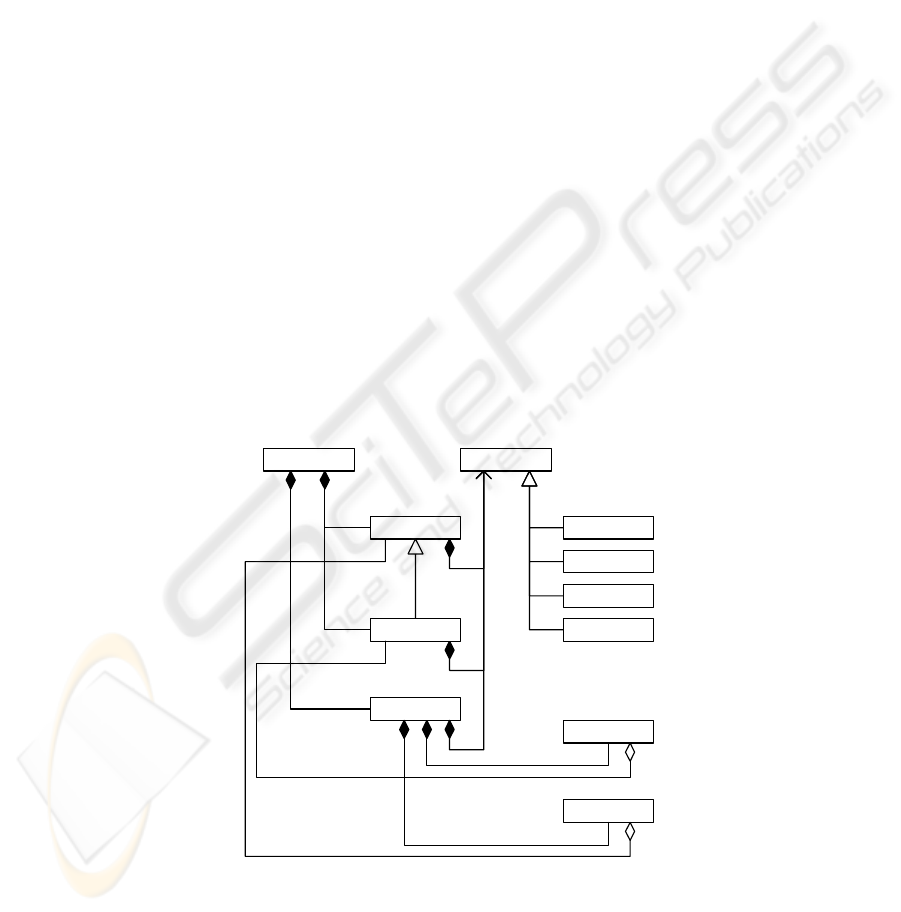
The structure of the system can be described according to the following data
model, Fig. 1. Here, the class
"model" is the root class for the entire model. Classes
"node<level1>" and "node<level2>" represent node elements of different types
or even hierarchical levels, the number of hierarchical levels is not limited.
1..*
1..*
1..*
1..*
1..*
attribute
attributeSingle
attributeVector
attributeMatrix
node <level2>
node <level1>
net
pin
model
...
rule
1..*
Fig. 1. Generic class model of a network structure
45

We emphasise that the set of node elements may be used for definition of different
kinds of interrelations. One kind of interrelations in the system will be modelled by a
corresponding network (e.g. material flow network, control flow network, etc.). Each
network has its own interpretation procedure (at least one). Obviously, the model
must also be able to represent several networks. Thus, network topologies involved in
the modelling are represented by instances of class
"net". The "pin" elements refer
to the nodes which are directly connected by means of the related network. Also
"rule"-elements, which may define legal network patterns for the relevant network,
are also included in the model.
Consequently, model instances are strongly associated with domains they repre-
sent. An application domain does prescribe the model architecture and validation
principles and rules.
2.2 Basic Concept of the XNetMod Language
Using the natural structure of the XML grammar, the model structure as it is shown in
Fig. 1 could easily be transformed into a linguistic object with four main semantic
parts: a) a set of functional elements in a network (
"node"-elements) – nodes in a
graphical representation of the model; b) a set of networks (
"net"-elements) with
their connections (
"pin"-elements) – edges in graphical representation of the model;
c) a set of verification rules (
"rule"-elements) which may define legal and illegal
network patterns for the relevant network; and d) a set of attributes (
"attr"-
elements) related to node elements, network definitions, and connection descriptions.
The network modelling language defines the structure – topology – of the technical
facility or process and provides the highest abstraction level for the description of the
process functional relations.
As mentioned above, an application domain provides an impact on syntactic and
semantic aspects of a modelling language, and, of course, defines substantially func-
tionality of associated interpreting tools. Thus, the specification of the
"node"-
element is given as
abstract and was separately extended for specific application
fields. From this point of view we can speak about a language family. Such semantic
aspects as validity intervals for model attributes can be treated only in connection
with a chosen application domain.
Taking into consideration this dependency of the language on a application do-
main, the decision was taken to concentrate the semantic/syntactic structure of the
language on the representation and validation of network properties in general and
connection features in local.
Consequently, the structure of the XNetMod language was developed in order to
support the development of network interpreters. For this reason, the definition of the
model has three parts – the definition of data model, the definition of relational
model, and the definition of verification model. The data model component provides
the interpreter with context information. The relational model – definition of model
topology – provides the interpreter with information for construction of algebraic
terms. The verification model possesses information for the term interpretation. Con-
sidering the activities related to modelling of ontologies (http://www.w3c.org/), we
would like to emphasise, that the developers of the XML language followed a similar
46

strategy in defining logical relations between the data entities. There, the separation
of data model and logical relations allowed modelling of complex semantics. The
interpretation of the semantic was also done by an interpreter – inference machine.
2.3 Model Verification Approach
Obviously, the system topology correctness is crucial for adequate processing of
simulation-based tasks. Therefore, special efforts were made in order to elaborate
proper methods for the network structure validation. The approach developed in-
cludes two mechanisms: a) the use of an XML specific tool – XML Schema – for the
verification of model elements; and b) the use of rules, which define allowed model
patterns, for verification of model structure.
For the XML-Schema-based mechanism, the definition of sophisticated XML
schemas for model components and relation between them must be provided. The
verification procedure can be implemented by means of available XML parsers, for
example by Xerces of the Apache Software Foundation (http://www.apache.org/).
It is not possible to verify the semantic of XML documents based only on the
XML Schema functionality. The core idea of this technique is the application of alge-
braic and pattern based methods for the model verification. The use of network alge-
bra for mapping of a network topology into a proper algebraic term can be found in
[4]. Two model check tasks were considered: a) model configuration check – check
of an attribute appearance and values, and b) network topology check – identification
of non-valid connections.
The formal description of network configuration check can be provided using the
set algebra. Let us consider a network G defined by sets of nodes N and links L :
G :=
〈N, L 〉, N := {N
1
, …, N
|
N
|
}, L := {L
1
, …, L
|
L
|
}.
(1)
The nodes N
i
, i=1(1)|N|, possess type attribute t
i
and simulation attributes a
ij
:
N
i
:= 〈t
i
, {a
i1
, …, a
i|N|
}〉, t
i
∈T, T := {T
1
, …, T
|
T
|
}, a
ij
:= 〈b
j
, v
j
〉.
(2)
Here b
j
∈B and v
j
∈IR are attribute name and value. Sets T :={T
1
, …, T
|
T
|
} and B :=
{b
1
, …, b
|B|
} collect application field dependent node types and attribute names. To-
pological structure of the network is given by links L ⊂ N×N . Nodes N
i
, N
j
∈N are
connected if ∃ L∈L, L=〈N
i
, N
j
〉. Additionally, a set of verification rules is also given
P ⊂ T × T × O × {0,1}, O :={>
⊗, ⊗<, ⊕}.
(3)
Configuration check: The validator verifies if attributes of nodes (2), which are in
direct connection, mach with patterns defined by rules (3). Here, attribute names,
types, values and other defined characteristics (e.g. physical units) can be addressed.
Topology check: Topology verification was realized using an algebra-based ap-
proach. Abstract operations "apply left" (>⊗), "apply right" (⊗<), "join" (⊕), etc.,
were defined for mapping of a network graph (1) in a proper algebraic term. The
verification is provided by a specialised interpreter which is able to interpret the alge-
braic term symbolically or numerically with respect to rules and operations (3).
47
3. Modelling Process Example
The process of a model building can be divided into two activities: definition of a
model on semantic level and its formalization using an interpretable modelling lan-
guage. The language chosen for the semantic was UML. The process shown is sup-
ported by a real application domain: modelling of forest fire extinguishing tasks.
The importance of forest fire prevention, extinguishing, and management is well
known, especially in the Mediterranean region. In case of forest fire, there are re-
sources that must be supervised: human, land and air resources. Every kind of re-
source has its own properties, and, in case of fire, is implemented in a different way.
A simulation based training system for forest fire officers was developed in frame-
work of
XnetMod research project (see the Acknowledgements).
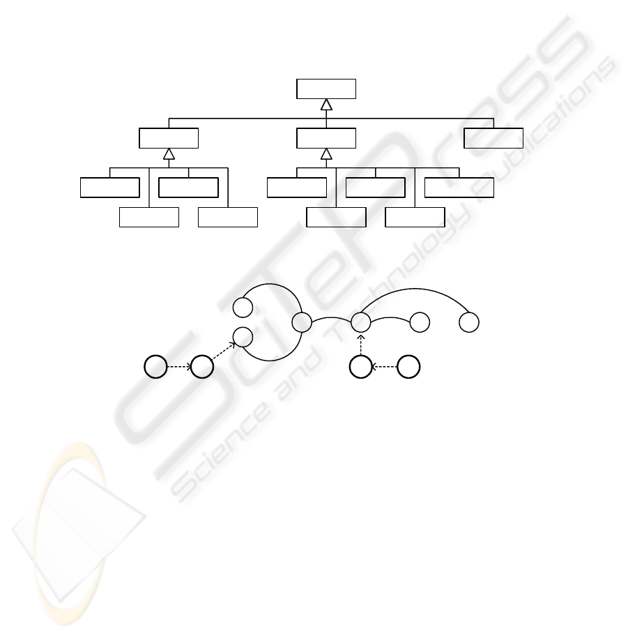
node
resources
human equipment
vehicle aircraft
location
observer
office airbase
water population
crossroad
Fig. 2. Resource and location node hierarchy diagram
Cr1
Cr3 Cr4
Cr2
Ab1P1
Cr5
A1V1
Cr6
Fig. 3. Road and resources network example
The modelling of the system requires three main types of nodes – resources, loca-
tions, and crossroads. Fig. 2 models the relationship among the classes. Crossroads
connected by roads and provides the main system network. Resources and location
nodes related to the road network. In Fig. 3, a road network example with resources
and location nodes is shown. Here, Cr1 … Cr6 are crossroads, P1 and P2 are popula-
tions, Ab1 is an airbase, A1 is an aircraft, V1 is a vehicle. The figure depicts also
allocation links: P1 to Cr2, Ab1 to Cr4, V1 to P1, and A1 to Ab1. The following veri-
fication rules for this system can be formulated: a) a population must be linked to a
crossroad, b) vehicle must be linked to a road or crossroad, and c) aircraft must be
linked to an airbase.
Once the application domain model was defined in terms of UML, it was specified
using XnetMod language. Some code fragment of an XnetMod document is given:
48

<Model xmlns:xsi="http://www.w3.org/2001/XMLSchemainstance">
<Node Id="P1" Name="Cuenca" xsi:type="Node:Population">
<Inhabitants>50000</Inhabitants>
</Node>
<Node Id="CR1" rem="Calle" xsi:type="Node:Crossroad">
<Risk>100</Risk></Node>
<Net Id="map1" Name="roads">
<Pin Id="P1" rem="Autopista1" xsi:type="Pin:Highway">
<From>P1</From><To>CR1</To></Pin>
<Rule Id="R1" rem="Rule1" xsi:type="Rule:Instance">
<From>Node:Population</From><To>Node:Crossroad</To>
</Rule></Net></Model>
Conclusion
A language and process for producing verified model schemas was presented for
systems that can be described as networks structures, that is, systems made of interre-
lated components. The developed language could serve as the simulation basis for
such application related issues as supervision, control, and decision-making. XML
Schema technique was used to specify the language. One of the reasons for this was
the number of available facilities to deal with XML structures. The language defined
on an abstract level with adaptation possibility with respect to a relevant application
domain. The approach has been tested with such various domains as forest fire extin-
guishing tasks (as described within this paper) and gas/water distribution automation.
Acknowledgements
This work is part of the XnetMod (XML Based Modelling Language for Simulation of Techni-
cal Networks ) project (CRAFT IST-2001-52057) partially funded by the European Commis-
sion. Contractors of the project are: ELPRO Prozessindustrie und Energieanlagen GmbH (co-
ordinator) (Germany), SIMPOWER Simulator Systeme GmbH (Germany), Investigacion y
Programas S.A. (Spain), ACEBO, C.B. (Spain), and RTD performers: Fraunhofer Institute for
Production Systems and Design Technology (Germany) and Universidad Politécnica de Ma-
drid (Spain).
References
1. Broy, M.: Object-oriented programming and software development – critical assessment. In
Programming Methodology. Springer-Verlag. Berlin Heidelberg New York (2003) 211-222
2. Fritzson P. Principles of Object-Oriented Modelling and Simulation with Modelica 2.1
Wiley-IEEE Press (2004)
3. Abdullah M.S, Benest I., Evans A., And Kimble C.: Knowledge Modelling Techniques for
Developing Knowledge Management Systems. In Proceedings of the 3rd European Confer-
ence on Knowledge Management. Dublin, Ireland, September 2002 (2002) 15-25
4. Stefanescu G.: Network Algebra. Springer-Verlag. Berlin Heidelberg New York (2000)
49
