
Analysis of Software Measures Using Metrology
Concepts – ISO 19761 Case Study
Alain Abran and Asma Sellami
École de technologie supérieure – ETS
Université du Québec, Montréal, Québec, Canada
Abstract. To help identify the strengths of proposed software measurement
methods, this paper proposes an analytical approach based on metrology con-
cepts documented in the ISO International Vocabulary of Basic and General
Terms in Metrology. This approach is illustrated with a case study using one
specific functional size measurement method recognized as an ISO standard:
COSMIC-FFP (ISO 19761). The case study documents the metrology concepts
addressed in this ISO standard, either in the design of this measurement method
or in some of its practical uses. It illustrates, for instance, that the design of
COSMIC-FFP encompasses a large number of related metrology concepts. It is
suggested that such a review using metrology criteria be used to analyze other
software functional size measurement methods, as well as other software meas-
ures suggested to industry.
1 Introduction
Hundreds of software measures have been defined in the software engineering
domain and proposed to industry. However, only the following have successfully
undergone the rigor of international standardization: the quality measures in the ISO
9126 series [8], and three functional size measurement methods, among them ISO
19761 – COSMIC-FFP [10]. Software functional size measures are used in particular
to compare the productivity of software projects (internally or across organizations),
for project effort estimation and for the control of functional changes over a project
life cycle. The use of such standardized measures is important to ensure comparabil-
ity of measurement results between projects and between organizations; indeed, it
would not be relevant to compare numbers based on distinct (and not standardized)
measurement methods. Without the use of standards, ideally those officially recog-
nized internationally, software agreements between customers and suppliers are prone
to a variety of interpretations and, often, to conflicts.
A large number of software measures are defined based on the intuition of their au-
thors. W
hen subjected to the scrutiny of researchers, they are often investigated only
from the perspective referred to as “measurement theory” (i.e. their mathematical
properties) [5, 6, 11]. However, in other science and engineering disciplines, it is the
domain of knowledge referred to as “metrology” that is the foundation for the devel-
Abran A. and Sellami A. (2004).
Analysis of Software Measures Using Metrology Concepts – ISO 19761 Case Study.
In Proceedings of the 1st International Workshop on Software Audits and Metrics, pages 69-84
DOI: 10.5220/0002685500690084
Copyright
c
SciTePress

opment and use of measurement standards, measurement instruments, and measure-
ment processes [3].
In this paper, we propose to use our initial modeling [2] of the sets of measurement
concepts documented in the ISO International Vocabulary of Basic and General
Terms in Metrology – VIM [7] to investigate whether or not the full set of metrology-
related concepts has been taken into account in the design and application of software
measures. To illustrate this approach, one specific type of software measure, that is,
COSMIC-FFP (ISO 19761), a functional size measurement (FSM) method, has been
selected as a case study. This choice was based on the following criteria: 1) when
compared to other types of software measures, FSM methods are supported by much
more detailed operational descriptions than those for most other software measures;
2) only software measures of this type have undergone the rigor and scrutiny of inter-
national standardization and have reached the status of official ISO standard (it
should be noted that the ISO 9126 series, with its set of definitions of quality meas-
ures, is an ISO technical report rather than an international standard per se).
This paper will therefore use ISO 19761 [10] for illustrative purposes to explore
whether or not such a software measure encompasses most – if not all – of the classic
metrology concepts.
The paper is organized as follows: Section 2 presents an overview of the metrol-
ogy concepts documented in the VIM and of a specific FSM method, ISO 19761
standard (COSMIC-FFP). In section 3, metrology-related concepts are identified in
the design of COSMIC-FFP; in section 4, measurement process-related concepts are
described; and in section 5, measurement instrument-related and measurement re-
sults-related concepts using an RUP/COSMIC-FFP-related software prototype tool
are presented. Section 6 contains a summary of this analysis of COSMIC-FFP with
respect to metrology, along with some concluding observations.
2 Overview of VIM and COSMIC-FFP
2.1 Metrology - VIM
Metrology is the science of measurement [7] and includes the set of methods de-
signed to perform the measurements and to provide a sufficient level of confidence in
the measurement results. To carry out a measurement, it is necessary to compare an
unknown quantity with a quantity of the same kind which has become a reference
through quantification by a measuring instrument. Metrology encompasses all aspects
of measurement (theoretical and practical) according to a measurement method de-
sign and in all domains of science and technology.
Six categories of metrology concepts are described in ISO VIM [7]:
1. Quantities and units
2. Measurements
3. Measurement results
4. Measuring instruments
70

5. Characteristics of the measuring instruments
6. Measurement standards – Etalon
Our initial modeling of the interrelated terms of this vocabulary, organized by cate-
gory as above, is presented in Appendix A, either in the form of process models
where appropriate, or in structured tables when the interrelated terms are, for in-
stance, enumerative. In particular, the expression “topology of concepts” has been
used to highlight the existence of links between related concepts. In this paper, we
use the models and tables in Appendix A extensively to analyze not only the design
of the COSMIC-FFP measurement method, but also the application of this FSM
method.
Two of the six metrology categories of concepts are related to some aspects of the
design of measurement methods, that is: “quantities and units” and “measurement
standards - etalon”. The other four categories are related not to the design of a meas-
urement method itself, but rather to the application of a measurement design with a
measuring instrument and to the quality characteristics of the measurement results
provided by this measuring instrument (including the inherent related degree of un-
certainty of the measurement results).
2.2 Overview of COSMIC-FFP
Software size can be assessed either by measures of length (for example, lines of
source code in a module, pages in a requirements specification document) or func-
tionality (for example, function points). Functional size measures can be derived
directly from the specifications and can be obtained fairly early in the development
life cycle, which makes them useful both for planning purposes and during the whole
project life cycle.
The first generation of FSMs was developed in the late 1970s, followed by a large
number of variants. It is only in the early 2000s that a second generation of such
measures has emerged and been rapidly adopted as an international standard [10]:
ISO/IEC 19761: 2003 COSMIC-FFP: A functional size measurement method. This
FSM method is based on the application of a set of models, rules, and procedures to a
given piece of software, as it is defined from the perspective of its Functional User
Requirements – FURs. By design, the measurement results provided by this method
are independent of the technology. This ISO FSM standard is suitable for measuring
various types of software (business application software, real-time software or Web-
based and Internet applications, and so on), independent of technologies, develop-
ment, and implementation decision approaches. By design, and in conformity with
ISO 14143-1 [9], the standard is independent of the implementation decisions em-
bedded in the operational artifacts of the software to be measured and excludes both
the software quality and technical characteristics.
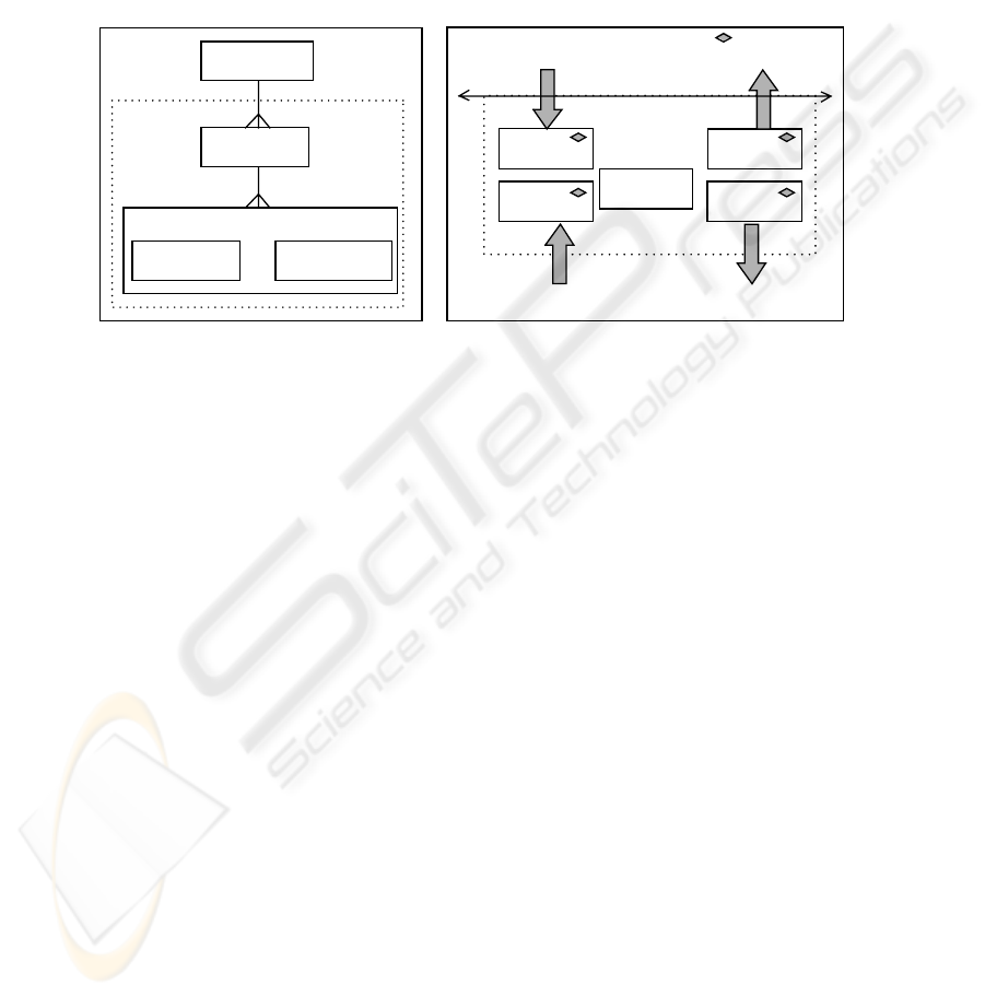
COSMIC-FFP takes into account that software FURs can be decomposed into a set
of functional processes, and that each of these functional processes constitutes a
unique set of data movements and/or data manipulations (Fig. 1). The COSMIC-FFP
software model distinguishes four types of data movement: entry, exit, read, and
write, as identified in the context model (Fig. 2). By convention, all data movements
move data contained in exactly one data group. Entries move data from the user
71
across the boundary to the inside of the functional process; exits move data from
inside the functional process across the boundary to the user; reads and writes move
data from and to persistent storage.
In COSMIC-FFP, each data movement is assigned a single unit of measure of 1,
which is, by convention, equal to 1 Cfsu (Cosmic functional size unit). The total size
of the software being measured corresponds, therefore, to the addition of all data
movements recognized by the COSMIC-FFP FSM method. See [1, 10] for the de-
tailed measurement rules.
Fig. 1.
A generic software model for
measuring functional size [1]
Manipulation
Boundary
Entry
Exit
Write
Read
Functional
process
Users
Storage
Fig. 2. COSMIC-FFP Movement types [1]
: Data movement type
sub-processes
Functional User
Requirements
Data Movement
type
Data Manipulation
type
Sub-process types
Softwa re
Functional
Process type
3 Analysis of COSMIC-FFP design
3.1 Quantities and units
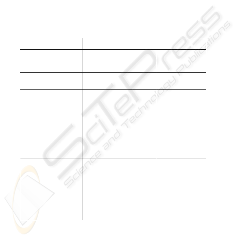
The first analysis focuses on the design of COSMIC-FFP using the set of metrol-
ogy concepts on “quantities and units”, as described in Table A.1 of Appendix A. The
results of this analysis are presented in Table 1. As can be observed from Table 1, the
design of COSMIC-FFP allows quantification of a (measurable) quantity (that is, a
movement of a single data group in a functional process) in well-defined units (that
is, Cfsu). However, the COSMIC-FFP standard does not yet include any derived
measure, and its system of quantities comprises a single base quantity, that is, the
Cfsu itself.
The symbol for the base COSMIC-FFP quantity is the visual representation of
"Cfsu", and this symbol is used to represent the unit of measurement, or 1 Cfsu. In the
current state of the art for FSM, there is again only one unit of measurement, that is,
there are no derived or off-system units.
It should be noted next from Table 1 that there are not yet either multiples or sub-
multiples of a unit of measurement (like kilograms or centigrams). This lack of multi-
72
ples and submultiples applies to the other ISO-recognized FSMs as well. Similarly, in
COSMIC-FFP, there is only one level of granularity and formally recognized conven-
tional reference scale, which is the level of a single data group movement, no matter
how many attributes there are within this data group. The COSMIC Guide [1] recog-
nizes, however, that some measurers might want to define their own – nonstandard-
ized – finer levels of granularity (for example, at the level of data group attributes);
however, there is not yet a consensus on this topic, and therefore there is not yet a
basis on which to develop an international consensus for such a measurement conven-
tion.
In the last section of Table 1, the analysis of the set of concepts related to “value”
(of a quantity) is more complex because, in our opinion, it includes concepts related
both to the measurement method design and to its application in specific instances.
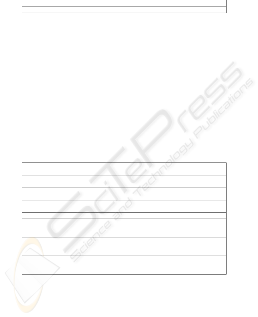
Table 1. Quantities and Units metrology concepts in COSMIC-FFP
Metrology [7] ISO 19761 [10] and COSMIC
Implementation Guide [1]
Clause in ISO 19761
[10]
System of quantities
(Currently, only one base quantity
is included)
Base quantity Cfsu
Derived quantity (none yet defined)
2.5 COSMIC-FFP
measurement phase
Dimension of a quantity
(not explicit)
Quantity of dimension one /
Dimensionless quantity
(undetermined)
2.7 Functional size
measurement context
Unit (of measurement)
= 1 Cfsu
Symbol of a unit = Cfsu
System of units Not applicable
Coherent (derived) unit Not applicable
Coherent system of units Not applicable
International system of units,
SI
Not applicable
Base unit = 1 Cfsu
Derived unit None
Off-system unit None
Multiple of a unit None yet defined
Submultiple of a unit None yet defined
2.5 COSMIC-FFP
measurement phase
Value (of a quantity)
Value of functional size
True value Not yet explored
Conventional true value = In practice, obtained by expert
judgment
Numerical value = Result of a measurement: func-
tional size
Conventional reference scale/
Reference-value scale
= Scale = a data group movement
(independently of data movement
type, and number of data attributes
moved). Each data group movement
is assigned a value of 1 Cfsu
2.2 COSMIC-FFP
measurement process
model
73

Finally, a “conventional reference scale/reference-value scale” represents particu-
lar quantities of a given kind, an ordered set of values, continuous or discrete, and is
defined by convention as a reference for arranging quantities of that kind in order of
magnitude. In COSMIC-FFP, this concept corresponds to the scale of a movement of
a data group (entry, exit, read, and write, abbreviated by convention as “E” for entry,
“X” for exit, “R” for read, and “W” for write). Each movement of a data group has a
size of 1 Cfsu in COSMIC-FFP. There is, of course, a standard definition of what is
recognized as a “data group” by COSMIC-FFP. In addition, it represents a discrete
set of values composed of E = X = R = W = 1.
In COSMIC-FFP, the “numerical value” of the software to be measured corre-
sponds to the addition (in the same software layer) of the individual values assigned
to each identified movement of a data group. This addition provides the “numerical
value” of the software to be measured. In short, “numerical value” and “conventional
reference scale” are explicitly defined in the COSMIC-FFP standard [10].
3.2 Measurement standards – Etalon
In measurement for the sciences and for engineering, it is taken for granted that
there should exist “measurement standards - etalons” for calibrating and verifying the
measuring instruments and to ensure the consistency of measurement results across
individuals, organizations, and nations. However, this metrology concept has not yet
been discussed in the software measurement literature, nor has it been the focus of
attention of practitioners. In software measurement, what could be close to this con-
cept, and its related sub-concepts in Table A.4, are the case studies documented for a
few of these software FSM methods.
4. Analysis of Measurement with COSMIC-FFP
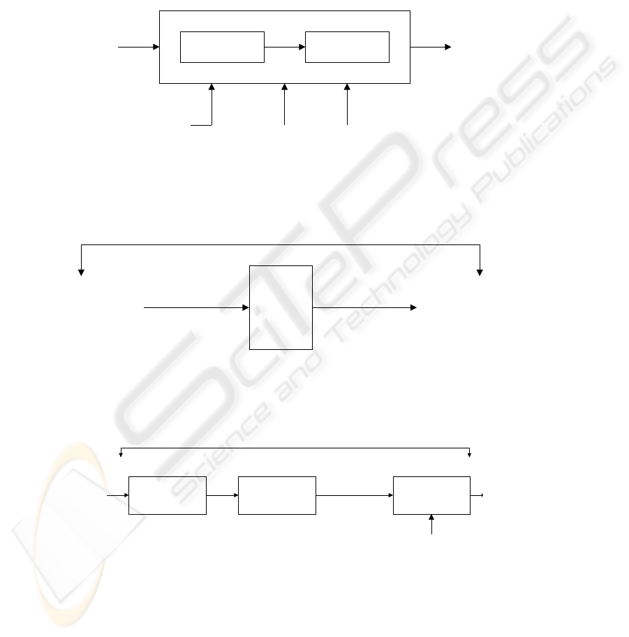
In the VIM, the term “measurement” refers to the category of terms for the “set of
operations” required to obtain a measurement result (see also Fig. A.1), and this is
instantiated through the generic measurement process described in Fig. A.2.
This figure illustrates, with the use of a graphical representation of a process, dif-
ferent concepts related to the concept of “measurement”. It should be noted that, in
metrology, the “quantity to be measured” by means of a set of operations (and a
measuring instrument) is also called a “measurand”, that is, the input quantity that is
applied to a measuring instrument (Fig. A.2).
As described in Fig. A.2, a measurement procedure requires, as input, a meas-
urand, which corresponds in COSMIC-FFP to the FURs, and produces a measure-
ment result which represents a numerical value of functional size. An instantiation of
a measurement procedure for a specific measurement includes an operator to carry
out the measurement process (here, the measurer), the measurement method itself
(here, the standard method), and the influence quantities (here, conditions that could
influence/ bias measurement results). The operator corresponds to the user of the
method (the measurer). The COSMIC-FFP measurement method is explicit, and the
74
influence quantities include, for example, user skills, capability of the given docu-
mentation to perform measurement, allocated time, etc.
In COSMIC-FFP, the quantity to be measured (the “measurand”), as determined
by the software users through the functional requirements (FURs), will be trans-
formed through the prescribed set of logical operations to provide a numerical value
(a number representing software functional size). This number is associated with a
size unit (Cfsu) to represent the measurement result (numeric value).
In the ISO standard for COSMIC-FFP [10], the standardized definitions of the
concepts relevant to this method are specified in Clause 3, while the logical sequence
of operations described as “measurement activities” are specified in Clause 6. In our
opinion, these definitions and measurement activities should meet the metrology
concepts for “principle of measurement” and “method of measurement” defined in
the VIM [7]. However, these two VIM concepts, which correspond to the foundations
of a measurement from a metrology perspective (Fig. A.1), are not described in finer
levels of detail in the VIM with a view to verifying whether or not there is a full cor-
respondence, in the COSMIC-FFP standard, of their underlying subconcepts.
It should also be noted that, in the software measurement literature, the concepts of
“measurement signal” and “transformed value” are not discussed explicitly. Even
though these two sets of terms are not discussed in the ISO standard [10], they are
explicitly presented and discussed in the COSMIC guide for the implementation of
the ISO 19761 standard [1]: they correspond to the set of concepts included in what is
categorized as the “mapping phase” between the documentation of the FURs and
their mapping to COSMIC-FFP. In an explicit way, this COSMIC guide [1] pre-
scribes that the transformed value be obtained by the following sequence of opera-
tions:
"The measurer should identify the boundaries of the software to be measured,
identify all functional processes, triggering events and data groups, map them in the
software context model using the COSMIC rules, identify the layers, identify the data
movements in each function process and sub-process, and determine the COSMIC
size measurement by adding the results." [1].
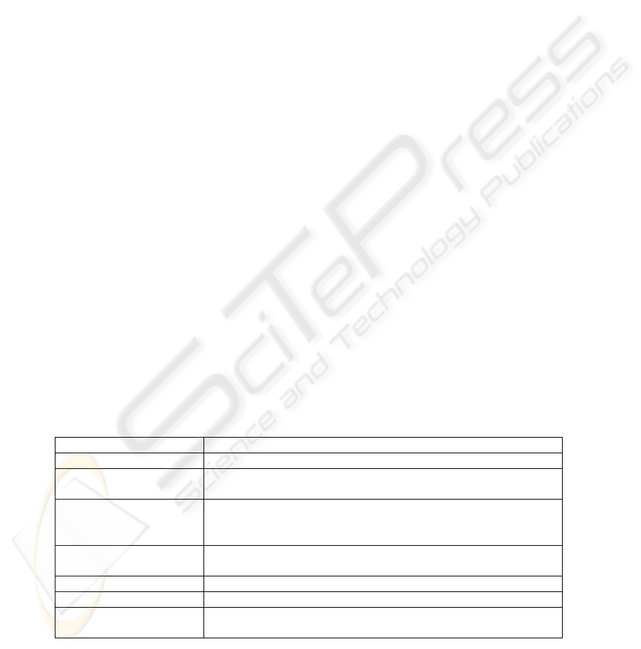
A summary of these correspondences of measurement metrology concepts in
COSMIC-FFP is presented in Table 2.
Table 2. Measurement metrology concepts in COSMIC-FFP
Metrology [7] COSMIC Implementation Guide of ISO 19761 [1]
Measurand An FUR in an artifact of the software to be measured
Measurement signal Mapping phase: measurement context and COSMIC-FFP software
models
Measurement procedure Measurement phase: rules and methods to be applied to the output
of the Mapping phase as represented in the COSMIC-FFP generic
software model
Measurement result Functional size of the generic software model of the FUR: nu-
merical value
Operator The measurer
Method of measurement See ISO 19761: COSMIC-FFP [10]
Influence quantity For example: measurer expertise, quality of FUR documentation,
time allocated for measuring, etc.
75
5 Analysis of COSMIC-FFP Measuring Instruments and
Measurement Results
To explore the metrology concepts relevant to the measuring instruments and
measurement results, we use as a case study the prototype of COSMIC-FFP devel-
oped in the RUP-Rational Rose environment, as described in [4].
5.1 Measurement standards – Etalon
In scientific and engineering (and also commercial) environments, measurement is
normally carried out using measuring instruments which are calibrated from reference
standards/etalons. As illustrated in Fig. A.3, for example, the “measuring chain”
represents the series of elements of a measuring instrument or system. In [4], the
equivalent of a measuring chain is described as including the path of the measurement
signal from the input as an FUR description of the Use Cases, the measurement proto-
type itself, and the output as the measurement results. More details of the mapping of
this case study are presented in Table 3.
The notion of the measurement scale is also within the set of concepts related to
the measuring instruments, and includes a dozen subconcepts, as illustrated in Fig.
A.7. However, the application of these metrology concepts essentially depends on the
presence of multiples and submultiples of a unit of measurement. Again, in the cur-
rent state of the art of software FSM, these subconcepts are not present and therefore
cannot be discussed here.
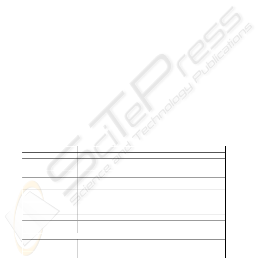
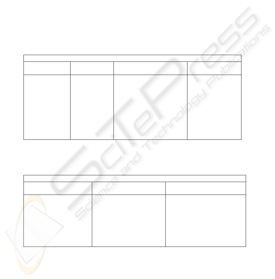
Table 3. Measuring Instrument metrology concepts and COSMIC-RUP prototype [4]
Metrology [7] COSMIC – RUP Prototype [4]
Measuring chain FUR + COSMIC-RUP prototype + functional size results in [4]
Measuring system: Complete set of elements of the software prototype + manual proce-
dures
Detector Prototype function which extracts the elements to be measured
Measuring transducer The mapping solution between COSMIC and UML-RUP concepts
in [4]
Measuring instrument In the COSMIC-RUP prototype, the set of functionalities to imple-
ment the COSMIC-FFP measurement rules
Material measure Measurement results, displayed on output screens and saved in
memory
Integrating instrument Not in the prototype (since it does not handle any 'other quantity')
Measurand Set of FURs
Another quantity Not in the prototype
Details of a measuring instrument:
Displaying/ Indicating
device (+index)
Display screens of measurement results
Recordin
g
inst
r
ument/ Prototype function, which allows recording in the database
76
Recording device
Note: not all details appear in this table
5.2 Measurement results
In all measurement instantiations, a measurement result is usually associated with a
measurement uncertainty, because, in practice, no perfect measurement process ex-
ists. Measurement uncertainty is defined in metrology as a parameter characterizing
the dispersion of the values that could reasonably be attributed to the measurand, that
is, the interval centered on the measured value and in which it is very probable that
the true value and the conventional true value will be found. In the current state of
software FSM knowledge, the true value is generally obtained by consensus among
measurement experts. The difference between the results obtained by a measurer (or
by a measuring instrument) and by an expert represents the error.
In [4], the measurement results of a case study are presented; however, it is a
small-scale case study only for the purpose of demonstrating the technical feasibility
of the automation concept of the COSMIC-FFP standard in the RUP/Rational Rose
environment. To obtain statistically significant results with information about the
concepts included in the detailed topology of measurement results, much larger case
studies will be required. Details of the mapping of this case study are presented in
Table 4.
Table 4. “Measurement Results” metrology concepts and COSMIC-RUP prototype [4]
Metrology [7] COSMIC – RUP Prototype [4]
Measurement result types
Indication Detailed results, summarized, according to the proposed
templates in [1]
Uncorrected result Measurement results, prior to human intervention to add
missing information
Corrected result Revised measurement results, after addition of missing in-
formation
Mode of verification of results
Accuracy of measurement In [4], this characteristic is only tested with a small-scale
case study. There are not enough cases to obtain significant
statistically quantitative knowledge of this characteristic
Repeatability A software tool normally provides the same results in repeat-
able conditions (needs to be verified by further experimenta-
tion)
Reproducibility Same as above
Uncertainty of measurement
and 8 other related concepts
Characteristic not yet explored
5.3 Characteristics of measuring instruments
We have modeled the “characteristics of measuring instruments” from both the
quantitative and qualitative viewpoints described in Table A.3.
77

5.3.1 Quantitative viewpoint
In the COSMIC-RUP prototype [4], several quantitative metrology concepts can be
observed: for example, in the description of its operational conditions (that is, the
FUR must be modeled according to an RUP process based on UML formalisms) and
of its boundary conditions (that is, the prototype currently deals with only one soft-
ware layer at a time). Further mappings are presented in Table 5.
Table 5. Quantitative viewpoint of “Characteristics of Measuring Instruments”
Metrology [7] COSMIC –RUP Prototype [4]
Rated operating conditions It is necessary to model FURs according to an RUP process
based on UML formalisms
Limiting conditions The prototype deals currently with only one software layer at a
time
Reference conditions
Example: a functional process must have more than 2 data
movements
Instrument constant The tool should preserve its metrological characteristics over
time (even, for example, when there is a change of version in
each of its software components)
Response characteristic
New levels of units of measurement have been defined in the
tool (Ufsu and Sfsu), but the response characteristics have not
yet been analyzed
Sensitivity A particular case has been identified; for example, to indicate
whether or not it is possible to categorize correctly the read or
write movements. It is recognized that this categorization prob-
lem does not have any impact on the final size itself since the
numerical value for each data group movement = 1 independ-
ently of its category (for example, sensitivity = none)
Discrimination (threshold) 1 Cfsu, the minimum size of a change to an FUR
Resolution (of display
device)
Not yet investigated
Dead band Not yet investigated
5.3.2 Qualitative viewpoint
In the COSMIC-RUP prototype [4], the results of the analysis between the qualita-
tive viewpoint of “characteristics of measuring instruments” from Table A.3 are pre-
sented in Table 6. It must be noted here that the mappings with the concepts of the
functionality test (use errors and control errors), and even the measuring range or
working range concepts (nominal range, span, and nominal value) have not been
explored, since the appropriate experimental conditions were not available. (See Ta-
ble A.3 for the list of related metrology concepts).
78
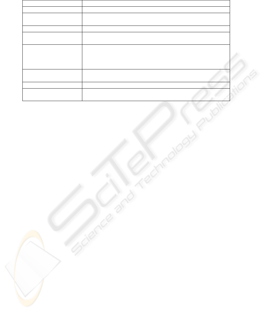
Table 6. Qualitative viewpoint of Characteristics of Measuring Instruments
Metrology [7] COSMIC-FFP: automated tool with RUP [4]
Stability Not yet investigated
Transparency COSMIC-FFP/ RUP prototype is a transparent instrument for the
measurement of a functional process
Drift Not yet investigated
Response time There is a time interval between the instant of the stimulus and the
instant of the response
Accuracy of a measuring
instrument
This was analyzed with only one case study, which was a small-
scale one. More case studies should be constructed and the results
analyzed to determine the accuracy of the results measured by the
prototype, and under which set of conditions
Accuracy class (class of
measuring instruments)
Not yet investigated
Freedom from bias Not yet investigated
Repeatability The prototype provides the same value for the same conditions of
measurement
6 Summary and conclusions
In software engineering, the analysis of software measures is usually discussed
from the perspective of measurement theory. We have proposed an approach here for
the analysis of some aspects of the strengths of software measures based on our mod-
eling of the set of metrology concepts documented in the ISO International vocabu-
lary of basic and general metrology terms (VIM). This was illustrated using one spe-
cific FSM method recognized as an ISO standard: COSMIC-FFP (ISO 19761).
The paper has documented the metrology concepts addressed in this ISO standard,
either in the design of this measurement method or in some of its practical uses. In
summary, it was observed that:
• On the one hand, the design of the COSMIC-FFP method covers a major-
ity of the metrology concepts described in the VIM dealing with the de-
sign of measurement methods;
• On the other hand, much larger-scale case studies will be required for the
study of the characteristics of measurement instruments as identified in
the VIM.
Measurement is recognized as a fundamental concept in engineering and provides
the information required to make key project decisions and take appropriate action. A
very large number of software measures has been proposed to industry to describe the
various characteristics of software in a quantitative manner, and much work remains
to be done in the study of both the design of software measurement methods and the
characteristics of measuring instruments for software measurement instrumentation in
industry.
Indeed, most of the metrology concepts related to measuring instruments still have
to be adequately explored by software engineers. It is suggested that the full set of
metrology concepts documented in the VIM be used as criteria to analyze the
79

strengths of other software FSM methods, as well as of other software measures sug-
gested to industry.
References
1. A. Abran, J. M. Desharnais, S. Oligny, D. St-Pierre, and C. Symons, "COSMIC
FFP Measurement Manual - Version 2.2, The COSMIC Implementation Guide for
ISO/IEC 19761: 2003," École de technologie supérieure – ETS, Montreal (Can-
ada) 2003. Available free at: www.lrgl.uqam.ca/cosmic-ffp
2. A. Abran and A. Sellami, "Initial Modeling of the Measurement Concepts in the
ISO Vocabulary of Terms in Metrology", 12th International Workshop on Soft-
ware Measurement – IWSM, Magdeburg (Germany) Oct. 7-9 2002, in Software
Measurement and Estimation, Shaker-Verlag, Aachen, 2002.
3. A. Abran, A. Sellami, and W. Suryn, "Metrology, measurement and metrics in
software engineering," Ninth International Software Metrics Symposium –
METRICS 2003, Sept. 3-5 2003, Sydney, Australia, IEEE Computer Society
Press, Los Alamitos, 2003.
4. S. Azzouz and A. Abran, "A proposed measurement role in the Rational Unified
Process (RUP) and its implementation with ISO 19761: COSMIC FFP," Software
Measurement European Forum SMEF 2004, Rome, Italy, Jan. 28-30, 2004.
5. N. E. Fenton and S. L. Pfleeger, Software Metrics: A Rigorous and Practical Ap-
proach: 2nd ed., PWS Publishing Co., 1997.
6. M. Hitz and B. Montazeri, "Chidamber and Kemerer's Metrics Suite: A Measure-
ment Theory Perspective," IEEE Transactions on Software Engineering, vol. 22,
pp. 267 -271, 1996.
7. ISO, International Vocabulary of Basic and General Terms in Metrology. Interna-
tional Organization for Standardization – ISO, Geneva, 1993.
8. ISO, ISO/IEC 9126-1 to 3: 2001, Information Technology – Software Quality
Characteristics and Metrics; Part 1: Quality model; Part 2: External metrics; Part
3: Internal metrics, International Organization for Standardization – ISO, Geneva
2001 to 2003.
9. ISO ISO/IEC 14143-1: 1998, Information technology -- Software measurement --
Functional size measurement -- Part 1: Definition of concepts, International Or-
ganization for Standardization – ISO, Geneva, 1998.
10. ISO ISO/IEC 19761: 2003, Software Engineering – COSMIC-FFP – A Functional
Size Measurement Method, International Organization for Standardization – ISO,
Geneva, 2003.
11. Zuse H., A Framework for Software Measurement, Walter de Gruyter, Germany,
Berlin, 1997.
80
Appendix A
The 6 categories of metrology concepts described in the ISO vocabulary of me-
trology [5] are:
1. Quantities and units: Table A.1
2. Measurements: Fig. A.1 and Fig. A.2
3. Measurement results: Table A.2
4. Measuring instruments: Fig. A.3, A.4, A.5, A.6 and A.7
5. Characteristics of the measuring instruments: Table A.3
6. Measurement standards – Etalon: Table A.4
A subset of the Tables and Figures from [8] are presented next.
Table A.1. Detailed topology of the Quantities and Units set of concepts
(Measurable) Quantity
Systems of
quantities
Dimension of a
quantity
Unit (of measurement) Value (of a quan-
tity)
Base quantity
Derived quantity
Quantity of
dimension one/
Dimensionless
quantity
Symbol of a unit
System of units
Coherent (derived) unit
Coherent system of units
International system of units
Base unit
Derived unit
Off-system unit
Multiple of a unit
Submultiple of a unit
True value
Conventional true
value
Numerical value
Conventional refer-
ence scale/Refer-
ence-value scale
Table A.2. Detailed topology of Measurement Results vocabulary
Result of a Measurement
Types of measurement
results
Modes of verification of
measurement results
Uncertainty of measurement
Indication Uncorrected
result
Corrected result
Accuracy of measurement
Repeatability
Reproducibility
Experimental standard deviation
Error (of measurement)
Deviation
Relative error
Random error
Systematic error
Correction
Correction factor
81
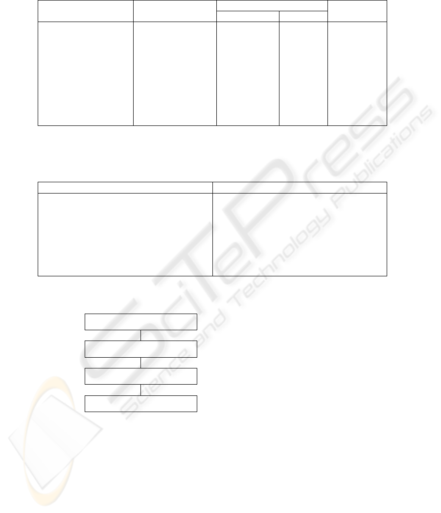
Table A.3. Detailed topology of the Characteristics of Measuring Instruments
Functionality test Quantitative Qualitative
Use Control
Measuring
Range
Rated operating condi-
tions
Limiting conditions
Reference conditions
Instrument constant
Response characteristic
Sensitivity
Discrimination
Resolution
Dead band
Stability
Transparency
Drift
Response time
Accuracy of a
measuring instru-
ment
Accuracy class
Freedom from bias
Repeatability
Error (of
indication)
Maximum
permissible
errors/ Limits
of permissible
error
Bias
Fiducial error
Datum
error
Zero error
Intrinsic
error
Nominal
Range
Span
Nominal
Value
Table A.4. Detailed topology of Measurement Standards / Etalons
(Measurement) Standard Etalon Conservation of a (Measurement) Standard
International (Measurement) Standard
National (Measurement) Standard
Primary Standard
Secondary Standard
Reference Standard
Working Standard
Transfer Standard
Traveling Standard
Traceability
Calibration
Reference Material (RM)
Certified Reference Material (CRM)
Metrology
Principle of Measurement
Method of Measurement
Measurement
Science of Measurement
Scientific Basis of a Measurement
Logical Sequence of Operations
Set of Operations
Fig. A.1. Measurement Foundations – High-level topology
82
Measurement Procedure
Measurand
Result of a
Measurement
Measurement
Signal
Transformed
Value
Operator
Measurement
Method
Influence
Quantity
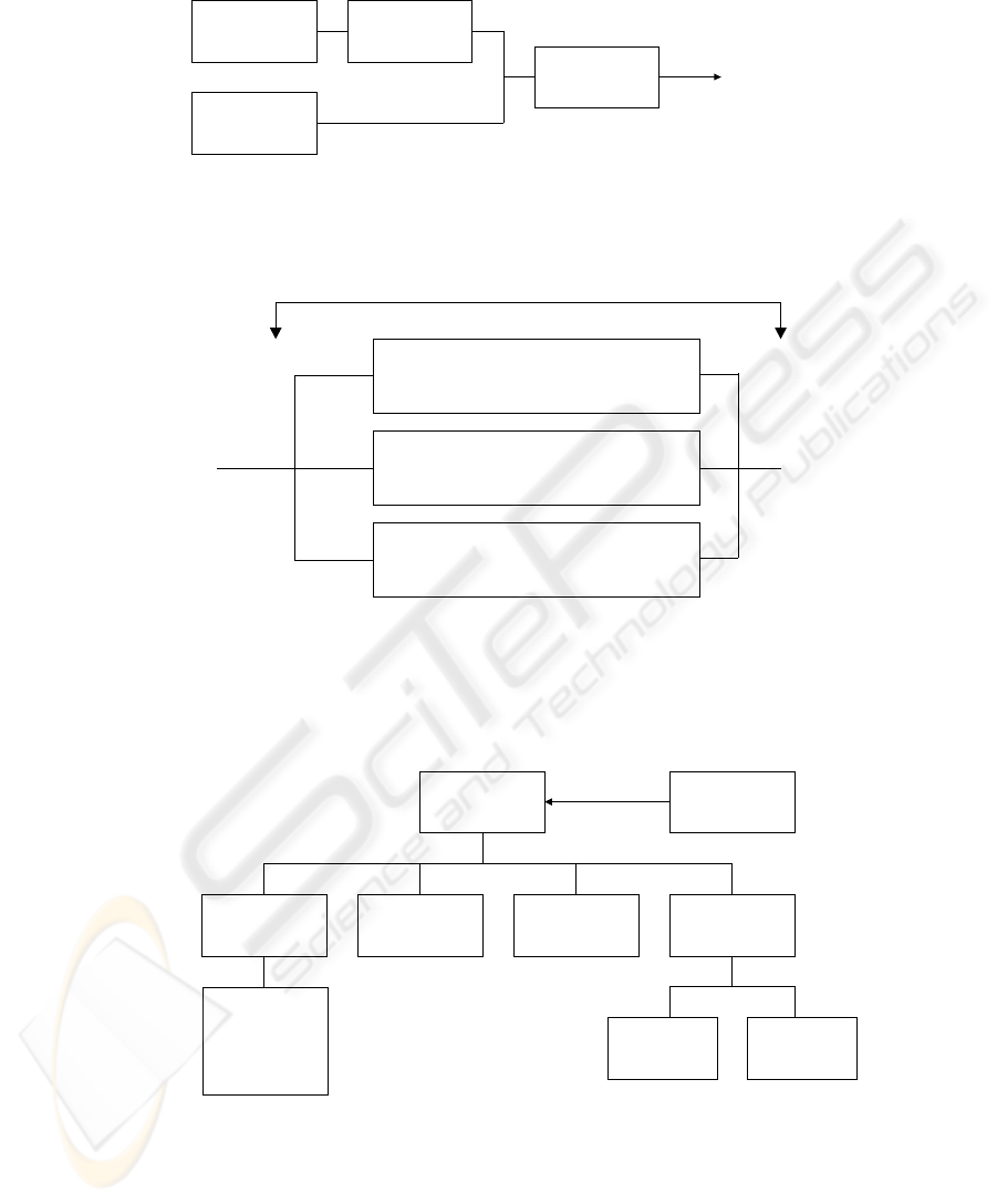
Fig. A.2. Measurement Process – Detailed topology of sub-concepts
Measuring
System
Stimulus
(Input Signal)
Response
(Output Signal)
Measuring Chain
Fig. A.3. High-level topology of Measuring Instruments
Measuring
Transducer
Measuring
Instrument
Correspondance
Read
Response
Measuring System
Material
Measure
Detector /
Sensor
Stimulus
Fig. A.4. Detailed topology of a Measuring System
83
Measurand
Another Quantity
Measuring
Instrument
Integrating
Instrument
Response
Fig. A.5. Integrating Instrument
and/or
and/or
and/or
Displaying (A/D) / Indicating (A/D)
Displaying Device / Indicating Device
Index
Recording (measuring) instrument
Rcording Device
Integrating
Measuring Instrument
Fig. A.6. Details of a Measuring Instrument
Scale
(set of marks)
Scale type Scale Division
Range of
indication
Scale spacing Scale Interval
Scale Numbering
Scale length
- Linear scale
- Nonlinear scale
- Suppressed-zero
scale
- Expanded scale
- Dial
Fig. A.7. Set of concepts related to scale
84
