
MODELING SYSTEM VARIATION
Ken Krechmer
International Center for Standards Research, 757 Greer Road, Palo Alto, CA 94303 USA
Keywords: System of constraints, order, Shannon entropy, communications systems, standards.
Abstract: This paper proposes that the mathematical relationship between
an entropy distribution and its limit offers
some new insight into system performance. This relationship can be used to quantify variation among the
entities of a system, caused by tolerance, options, specification or implementation errors, independent of
noise, impact communications system performance. Means to address these variations are offered.
1 INTRODUCTION
C. Shannon in his seminal work, The Mathematical
Theory of Communications (1963), describes a
communications system as a "...system of con-
straints...". This paper proposes that Shannon's
concept of a system of constraints describes a
specific form of order that may be quantified. Order
is defined as a fixed relationship; a special case in
probability theory, where p(a|b) = p(b|a) = 1. The
ordered nature of the system of constraints used for
communications is clear when the relationship
between the transmitter, transmission link and
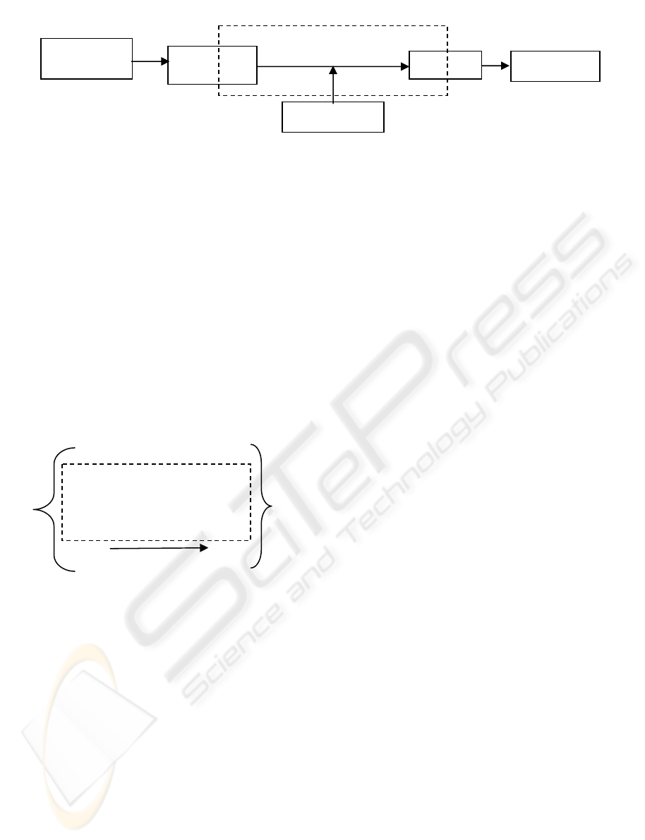
receiver is considered (see Figure 1). A properly
designed communications system in the absence of
noise, receives what is transmitted with a probability
of one. Understanding the mathematical form of the
system of constraints allows the quantification of
what is a properly designed communications system.
2 A MODEL OF A COMMUNI-
CATIONS SYSTEM
For communications to occur, any transmitter and
receiver must be related by a specific order, whether
it be human language (dictionaries and formal
syntax maintain the order), ASCII characters,
specific frequencies, voltages, or common protocols
between a transmitter and receiver. In the last four
examples order is maintained by reference to
published documents which may be termed
standards.
The philosopher I. Kant (1800) first elucidated
the idea
that a comparison is necessary for any form
of understanding. As example, in the course of
reading, a word appears of unknown meaning. The
reader refers to a dictionary which defines the
relationship between words and their meanings.
Assuming that the author also uses a similar
dictionary, the reader looks up the unknown word
Upon finding the same word (a comparison), the
reader now understands the meaning of the word.
This three phase process, apply common reference,
compare received signal to reference and identify
signal, occurs in any communications process. In
any communications system, order (in the form of a
common reference) must exist between the
transmitter and receiver to create the basis of
comparison necessary before communications can
occur.
Figure 1 diagrammatically shows the relationship
bet
ween a system of constraints and a com-
munications system. Each parameter of the
transmitter and receiver that directly relates to each
other and/or to the transmission link is a single set of
constraints. The multiple parameters of the
transmitter and receiver that directly relate to the
transmission link and/or each other are the system of
constraints (shown within the dotted line). Note that
the system of constraints is not congruent with the
Transmitter, Receiver or Transmission link in this
communications system model.
184
Krechmer K. (2005).
MODELING SYSTEM VARIATION.
In Proceedings of the Second International Conference on Informatics in Control, Automation and Robotics - Signal Processing, Systems Modeling and
Control, pages 184-190
DOI: 10.5220/0001162401840190
Copyright
c
SciTePress
System of constraints
Figure 1: Communications system
3 A MODEL OF A SIMPLE
INFORMATION CHANNEL
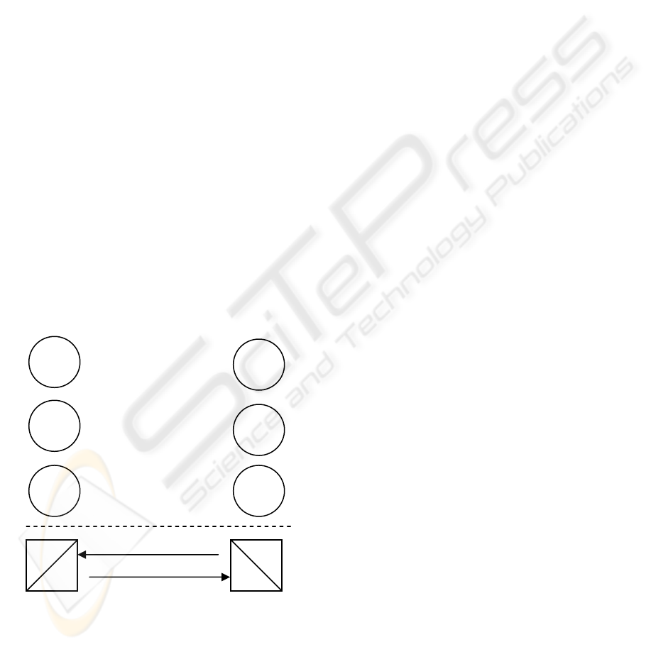
Figure 2 (from Abramson [1963] plus the dashed
rectangle S) presents a logical model of a simple
information channel consisting of a transmitter of
alphabet A with individual elements a
i
and total
elements t and a receiver of alphabet B with
individual elements b
i
and total elements r.
Alphabet A and alphabet B are related by the
existence of a common set of elements S, where S =
A ∩ B. Without noise, when S = A ∩ B and both r
and t ≥ n > 0 then S > 0. S = A ∩ B > 0 are the set
theoretic constraints that define the preexisting order
in Figure 2.
Figure 2: An information channel
This model represents the transmission link as
the probabilistic relationship between ordered pairs
of elements. The transmission link's constraints only
exist in the choice of the alphabets A and B. The
element pairs a
1
and b
1,
a
2
and b
2
, .... a
n
and b
n
are
each defined as a preexisting ordered pair. B.
Russell (no date) refers to this as a one-one
relationship. When a transmission link connects one
or more ordered pairs communications is possible.
Without noise, the sets A and B are related by the
ordered relationship of their elements where p(b
i
|a
i
)
equals one, for ordered pairs 1 through n. The set of
constraints termed S is formed by the order between
the elements of sets A and B and the common
alphabet size n. In Figure 2, the elements a
n+1
through a
t
and b
n+1
through b
r
are not ordered and
therefore not included in the set of constraints.
An example of such an information channel is a
human transmitter using the 26 letter English
alphabet a
t
through z
t
and a human receiver using the
same alphabet a
r
through z
r
. One condition for error
free communications is that the humans use a
common alphabet. This condition is a set of
constraints consisting of the 26 ordered pairs a
t
and
a
r
, b
t
and b
r
, .... z
t
and z
r
. Using this set of
constraints the humans are better able to
communicate. Without one or more preexisting
(before communications) ordered pairs, no reference
exists and no comparisons are possible. When the
same 26 letter alphabets are used by each person,
communications based on the alphabet can occur.
The ordered pairs of a communications system
may be created by chemical bonds (A-C, G-T in
DNA), preexisting written or spoken alphabets,
preexisting word dictionaries or the specifications of
the transmitter and receiver (electronic
communications) that constrain the implementation
of the transmitter, transmission link, and receiver
(entities). The definition of an entity here is
arbitrary, and indicates some independence from
other entities. The simplest entity is a single set
(e.g., set A or set B); a complex entity may consist
of multiple sets. The preexisting sets of constraints
are the system of constraints defining the rela-
tionship between two or more entities. In a
functioning communications system the
implementations of the transmitter, transmission link
and receiver are each bound by this system of
constraints.
Note that the set of constraints shown in Figure 2
is geometrically congruent with the system of
constraints shown in Figure 1. This suggests that
Figure 2 offers the basis for a more rigorous
description of the system of constraints.
4 A MODEL OF THE BOUNDS
ON A SET
Describing the relationship between the transmitter
and the receiver that enables communications first
requires a description of each of these entities. In
Information
source
Transmitter
Noise source
Receiver
Transmission link
Destination
a
1
a
2
.
a
n
.
a
t
b
1
b
2
.
b
n
.
b
r
Set of constraints, S
B
A
p(b
i
|a
i
)
MODELING SYSTEM VARIATION
185

information theoretic terms the system of constraints
defines the bounds of the information channel which
includes the transmitter and receiver. Figure 2
models the simplest possible information channel
between two entities as a single set of constraints, S.
Considering each entity as a single set, the in-
formation theoretic description of a single set (A) is:
his equation describes the entropy distribution
(H
bution and its
he relationship of an entropy distribution (e.g.,
fro
I = I(A;B) = H(B) – H(B|A)
bution [H(A)] in
Fig
(B|A) = log a
t
- (H(A)
I = log a
t
- (log a
t
- H(A))
herefore the mutual information, I (A; log a
t
) =
H (
g the term
sim
5 A MODEL OF AN INFOR-
Figure 1 defines a communications system.
s the case where the transmitter (t)
and
T
) of set A with n discrete random variables a
i
. The
limit of H(A) = log n which is the bound of the
entropy of set A and H(A) approaches this bound as
a limit. The logarithm of the number of elements of
the set along with the description of the set (in this
case, set A), describes the set bounds in information
theoretic terms.
Figure 3: Venn diagram of an entropy distri
bound
T
m a transmitter or to a receiver) to its bound is
shown in Figure 3. This relationship can be
explored using the concept of mutual information.
From Thomas and Cover (page 20) mutual infor-
mation (MI) is defined as:
M
onsidering the entropy distriC
ure 3 and its bound (log a
t
):
H
M
T
A). This explains that an entropy distribution
when considered in its own context is the mutual
information. A similar result is noted in Thomas
and Cover (page 20) as self-information. However
"its own context" may be either the bound of
H(A),which must equal the maximum entropy
distribution of H(A) or H(A) itself. If the context is
not the bound of H(A) or H(A) itself, then there are
two or more sets. The author proposes that a single
entropy distribution must be considered in the
context of its bound (e.g., log a
t
), as using the
context H(A) is self-referential. This form of self-
information is termed relative-information. This is
an important point, the relative-information in a set
only exists in context and the only logically
consistent context is the limit of the entropy
distribution. While this change in the context used
to define relative-information does not change the
value of mutual information, it has other
ramifications that are developed below.
Figure 3 is also useful in definin
)(log)()(
1
i
ni
i
i
apapAH
∑
=
=
−=
ilarity. By definition all sets that are similar to
H(A) fall within the limit of H(A). For the purpose
of creating a preexisting order (i.e., similarity), a
specific description of a single entity (which may
consist of multiple sets) may be made. This paper
terms such a description a similarity description as
the purpose of making such a description of an entity
is almost always to create or maintain similar
entities.
MATION CHANNEL WITH
BOUNDS
Focusing in, Figure 2 describes how an information
channel exists within a communications system
when the elements of two sets exist as ordered pairs
across a transmission link. Figure 3 develops the
relationship of a single entropy distribution to its
bound. Figure 4 combines the concepts shown in
Figure 2 with the relationships shown in Figure 3 to
model an information channel and its bounds using
Venn diagrams.
Figure 4 show
receiver (r) sets each have n ordered pairs. Log
a
t
is the bound of the transmitted entropy [H(A)] and
log b
r
is the bound of the received entropy [H(B)].
These bounds are shown as dotted concentric circles
around the related entropy H(A)
and
H(B)
.
Figure 4
is provided for visualization, not calculation, as the
shapes are idealized. The entropy [H(A) and H(B)]
always remains within its respective bound (log a
t
and
log b
r
).
log a
t
H(A)
log a
t
- H(A)
ICINCO 2005 - SIGNAL PROCESSING, SYSTEMS MODELING AND CONTROL
186

Figure 4 models how the relationship between,
and bounds on, H(A) and H(B) limit the maximum
mutual information. MI (the area within the solid
line lens in Figure 4) is the mutual information
transferred across the information channel between
the transmitter and the receiver.
Figure 4: Venn diagram of an information channel and its
bounds
The mutual information (MI) transmission equa-
tion for the information channel shown in Figure 4
is:
The mutual information (MI) is the Kullback
Leiber distance (Cover, 1991) between the joint
distribution [p(a
i
,b
i
)] and the product distribution
[p(a
i
)p(b
i
)]. Then log n, the upper limit of I(A; B), is
the maximum bound of the information channel.
I(A; B) = log n can occur only when the bound of set
A for the receiver = log n, and the bound of set B for
the transmitter = log n, are overlapping and
congruent. I(A; B) = log n only occurs when there is
no noise in the communications system.
MB (log a
n
; log b
n
), the mutual bound (the lens
shape enclosed in dotted lines in Figure 4), is
defined as the bound of an information channel.
Expanding the equation for MI above into separate
joint and product entropy terms:
When p(a
i
) = p(b
i
) = 1/n, the bound of set A for the
receiver = log n and the bound of set B for the
transmitter = log n. This is the mutual bound (MB)
of the information channel. The limit of MI, which is
MB, may be found by inserting 1/n for p(a
i
) and
p(b
i
). Then the equation for MB is:
MB = - (log n to 2 log n) + 2 log n
The product entropy term is 2 log n. The joint
entropy term ranges from -(log n to 2 log n)
depending upon the Kullback Leiber distance (Cover
and Thomas, 1991) which is determined by the noise
in a communications system (Figure 1) when a
t
= b
r
= n.
log a
t
MB
H(A)
That MB and MI both can be derived from the
Kullback Leiber distance is an indication that Figure
4 presents a realistic view of the relationship of the
mutual bounds to the mutual information. Using the
concept of mutual bounds it is possible to examine
the impact of variation of these bounds on the
performance of a communications system.
6 MODELING CONSTRAINTS
Consider two sets that have a high probability
relationship (p(b
i
|a
i
) near to 1) with each other but
where the number of elements in each set is different
(a
t
≠ b
r
) such as Figure 2. In the case where there is
no noise in an information channel and the
difference between the bounds of the two sets is the
variation caused by unordered elements in sets A
and B. Variation is defined as the existence of
elements of set A or B that are not ordered pairs.
Without variation between set A and set B, S = A ∩
B = log n. Attempting to hold a
t
= b
r
= n, thereby
eliminating variation, is the practice in electronic or
optical communications system design.
In an operating communications system the
relationship of a
t
to b
r
to n, for each set of constraints
is determined by the actual implementation of each
set pair A and B (Figure 2). Notice when a
t
or b
r
> n
the information channel is less efficient and this
effect is independent of noise. As the
communications system implementation approaches
optimum, a
t
= b
r
= n and p(b
i
|a
i
) = 1(no noise), then
MB approaches log n as a bound.
The term S (set of constraints), developed above,
is the bound of MB. MB describes the bounds of the
information channel in the presence of noise while S
describes the bounds of an idealized information
channel where noise is zero. When the noise is zero,
the effect of differences in the bounds of sets A and
B on communications system performance may be
examined.
Figure 4 is also useful to describe what is meant
by compatibility. All sets that have any degree of
∑
=
=
==
ni
i
ii
ii
ii
bpap
bap
bapBAIMI
1
,
)()(
),(
log)();(
H
(
B
)
MI
log b
r
∑∑
=
=
=
=
−=
ni
i
iiiiii
ni
i
ii
bpapbapbapbapMI
11
,
)()(log),(),(log)(
MODELING SYSTEM VARIATION
187

compatibility with each other have an MB that falls
within a bound S. MB = S = log n is the description
of the bound on the compatibility of the two sets
shown in Figure 2. A description of a
communications system is often made using
multiple related sets which creates a specific
preexisting order (i.e., compatibility). This paper
terms such a description a compatibility description
as the purpose of making such a description is
almost always to create or maintain compatible
entities.
7 QUANTIFYING VARIATION IN
A COMMUNICATIONS
SYSTEM
In specific designs or implementations of the
transmitter and receiver (when the link
characteristics are accounted for by the choice of
sets A and B), a
t
= b
r
= n may not be true for each set
of constraints in the system of constraints that bound
a communications system. When a
t
≠b
r
≠ n the
design/implementation of the system is less than
optimum. A reduction from the optimum is not
necessary undesirable but it should be defined to
prevent design or implementation errors. The
models developed above assist in evaluating any
variation from an optimum communications system
design.
Multiple implementations of an actual
transmitter or receiver are rarely identical. Figure 4
shows that differences in similarity directly impact
compatibility. Differences in the implementations
are caused by differences in the number of elements
of a transmitter set (a
t
), or receiver set (b
r
) caused by
some variation. Such variation (V), which is
independent of noise, is caused by errors or
misunderstandings in the definitions of order used
(e.g., similarity or compatibility descriptions), errors
in the implementations, or the implementation of
different options.
The relationship between a
t
and b
r
may be used
to quantify the total variation in incremental
parameters. Analog parameters (non-incremental)
are usually described using the concept of tolerance
which defines a bi-directional variation range. In
analog parameters, information variation within the
specified tolerance range is ignored; cases where the
information variation is beyond the specified
tolerance range are considered faults in common
engineering practice. For this reason this paper
focuses on incremental (non-analog) parameter
variation.
In the most efficient communications system
design the receiver will accept all the transmitter
sends and no more. This is shown as: log b
r
= log a
t
.
The information variation is (V) = |log b
r
– log a
t
| for
each set of constraints. The sum of the information
variation of all the non-ignored non-fault sets of
constraints (numbering x) in a communications
system is Σ V
i
for i = 1 to x. As p(b
i
|a
i
) goes to 1,
MI and MB increase. In the simplest
communications system, without noise, as V goes to
zero, MB goes to log n as a limit, the maximum
performance of the simplest communications
system.
The information channel shown in Figure 2
identifies two sets (alphabets) forming the simplest
communications channel. Assuming that these
alphabets define only one aspect of the coding, other
necessary parameters of the transmitter and receiver
may include bandwidth, initialization,
synchronization, training, framing, error control,
compression, session layer protocol, etc. The
description of these additional communications
parameters entails additional sets of constraints
which are each supported across an information
channel such as described in Figure 2.
The difference between MB and log n, not due to
noise, is caused by the effects of differing
implementations, defined by Σ V
x
. V terms could
also include the impact of variation related to the
design documentation as well as the
implementations. Variation may be caused by
differences in the similarity of: timer specifications,
buffer sizes or revision levels (when the revisions
modify the number of elements in any set in the
system of constraints); and also by different options,
or protocol layers, or revisions that modify the
number of elements in any of these at a single end of
the communications system.
When multi-protocol layer transmitters and
receivers have a variation somewhere in the system
of constraints, Σ V
x
will exist as a reduction in the
maximum possible MB. Given the current state of
design documentation (where each set of constraints
is not defined separately) the ability to compare sets
of constraints in each protocol layer of a complex
communications system to identify possible
variation is nearly impossible. And because of the
large number of combinations possible, the ability to
test all possible combinations of sets of constraints is
often close to impossible. Therefore, as
communications systems continue to become more
changeable and complex, the value of Σ V
x
is
ICINCO 2005 - SIGNAL PROCESSING, SYSTEMS MODELING AND CONTROL
188
increasing. A new mechanism, which is termed
adaptability, has emerged to address this problem
and decrease the effective value of Σ V
x
.
8 MODEL OF AN ADAPTABLE
SYSTEM
Order in a communications system includes
maintaining similarity of entities and maintaining
compatibility between entities. Order may also be
use to support adaptability between entities.
Adaptability, as used here, is a means to negotiate
the relationship between different, potentially
compatible entities for the purpose of selecting the
“best” pair of compatible entities required for the
communications system's application.
Figure 5 shows a multi-mode communications
system consisting of three independent transmitter
and receiver sets and one independent etiquette.
Communications is possible using any one set of the
compatible transmitters and receivers. The etiquette
shown in Figure 5 is used to negotiate the "best"
transmitter and receiver set for a specific
communications application. In this simple example
higher S, which offers more possible
communications states, is considered better.
Figure 5: A multi-mode system with one etiquette
Consider Figure 5. Transmitter set A and
receiver set B are compatible. Transmitter set C and
receiver set D are compatible and equal (in number
of states) to transmitter set E and receiver set F .
Transmitter set E and receiver set F have more states
than A and B
.
In this example none of the other
possible sets are compatible. In this case it is most
desirable for the transmitter and receiver selected for
operation to be E and F or C and D. Figure 5,
without the etiquette, could also be viewed as a
model of a 2G or 3G tri-band cellular mobile and
cellular base station. Figure 5 might also be viewed
as a model of a multi-mode software defined radio
(SDR).
For the purpose of creating a preexisting order, a
specific description of the negotiation procedures
among multiple possible information channels may
be used. Such a description is an adaptability
description which includes a mechanism to negotiate
among multiple possible information channels to
create or maintain adaptability. Such a mechanism
is termed an etiquette.
9 MINIMIZING VARIATION IN
COMMUNICATIONS SYSTEMS
Complex communications systems utilize multiple
layers of compatibility standards (e.g., protocols),
each of which may exhibit variation. For application
to application communications to be efficient, the
sum of the total communications system variation (Σ
V
x
) must be controlled, otherwise MB may be
significantly reduced. The ΣV
x
is very difficult to
calculate in multi-protocol layer systems with time-
independent processes, and testing all possible
variations is usually not practical.
Transmitters Receivers
A
B
A ∩ B = S
1
> 0
Etiquettes can ensure that complex
communications systems function properly at the
applications layer. Etiquettes define a fully-testable
independent protocol (from the data and control
layer protocols) whose purpose is to negotiate
among the parameters (most or all of the sets of
constraints) at the transmitter and receiver to select
the common sets known to fulfill the requirements
necessary for a specific communications application.
The purpose of an etiquette is to support
adaptability.
C
D
C ∩ D = S
2
= S
3
E F
In a communications system, multiple sets (used
in multiple OSI layers) exist to define a multi-
layered communications interface. Changes to the
sets describing the transmitter or receiver or their
implementations may create elements that are not
contained in the MB of a specific layer or reduce the
MB of a different layer (e.g., by changing a buffer
size which might reduce maximum packet length).
Such changes are a cause of compatibility problems.
When the changes to any compatible sets are a
Etiquette
E ∩ F = S
3
> S
1
MODELING SYSTEM VARIATION
189

superset of the previous compatibility sets, then Σ
MB remains constant or increases. However,
maintaining a superset in multiple layers of
communications protocols is problematic. The
ability to create a superset is made practical by
requiring that an etiquette is a single tree structured
protocol (which may be expanded and will always
remain a superset of prior instantiations). An
etiquette discovers and then negotiates between
multiple transmitter and receiver implementations
and their parameters at all required layers of the OSI
model (X.200) to identify and select
implementations that are most desirable for a re-
quired communications application. The etiquette
can perform such a negotiation based on knowledge
of the desired application, existing compatibility sets
or even known “bugs” by using specific revisions of
the sets of constraints in a desired application.
Etiquettes are already used in many
communications systems e.g., ITU G3 fax T.30,
telephone modems, ITU V.8, ITU digital subscriber
line transceivers G.994.1, IETF Session Initiation
Protocol, W3C XML; their properties have been
explored in Krechmer (2000). But the value of
etiquettes is not widely understood or employed. As
example, the 3G cellular standard, IMT-2000,
defines five different communications protocols.
Currently the means of selecting a specific protocol
stack is left to the designer. Existing multimode
cellular handsets and base stations sense the
strongest signal and give priority to higher
generation protocols over lower (a selection
mechanism). Such handsets and base stations can
support protocol selection, but cannot support
protocol negotiation. For a span of time, different
protocol stacks will be used in different geographic
areas and the negotiation that an etiquette enables is
of less value. Eventually however, multi-mode
cellular handsets and base stations will appear; then
an etiquette becomes more important, not only to
negotiate around incompatibilities that emerge as
more independent implementations and revisions of
the communications standards exist, but also to
allow the service provider to select the protocol that
optimizes system loading or optimizes geographic
coverage, or to allow a user to select the protocol
that offers the best economic performance. The use
of adaptability mechanisms is a system architecture
choice that significantly enhances the long term
performance of complex communications systems.
10 CONCLUSION
Shannon's theory has pointed the way toward more
efficient use of transmission links for over 50 years
by identifying the maximum possible data rate for a
given level of noise. The basic idea offered in this
paper is that Shannon's theory can also point the way
toward more efficient communications
specifications and equipment by quantifying the
effect of variation on communications systems.
Utilizing mechanisms to support adaptability then
offers the means to control variation in communica-
tions systems. Now that some communications
designs are closing in on the maximum possible
transmission link performance, it is time to address
the performance gains and system improvements
that can be achieved by controlling variation with
etiquettes.
REFERENCES
Abramson, N. (1963). Information Theory and Coding,
McGraw-Hill.
Cover, T. & Thomas, J. (1991). Elements of Information
Theory, John Wiley & Sons, Inc.
Kant, I. (1800). Logic, first published 1800 (General
Doctrine of Elements, para. 6, Logical Acts of
Comparison, Reflection and Abstraction).
Krechmer, K. (2000). Fundamental Nature of Standards:
Technical Perspective, IEEE Communications
Magazine, Vol. 38 No. 6, p. 70, June. Retreived from
http://www.csrstds.com.
Russell, B. (no date). Introduction to Mathematical
Philosophy, page 14, Simon and Schuster.
Shannon, C. E. & Weaver, W. (1963). The Mathematical
Theory of Communications, page 58, Theorem 8,
University of Illinois Press, Urbana and Chicago IL,
USA.
ICINCO 2005 - SIGNAL PROCESSING, SYSTEMS MODELING AND CONTROL
190
