
3D AUTOMATIC LOCATION DETECTION BASED ON SOUND
LOCALIZATION
Darun Kesrarat and Paitoon Porntrakoon
Autonomous System Research Laboratory, Faculty of Science and Technology
Assumption University Ramkamhaeng 24 Huamark, Thailand
Keywords: TDOA, moving-microphone array, angle direction, distance determination.
Abstract: Video conference systems have been widely used. A fix video camera shoots a scene is lacking in changes.
There is a method that the computer-controlled camera shoots and finds the sound source. Microphone
arrays and distributed microphone arrays are used to localize the sound source based on time delay of arrival
(TDOA). In order to minimize the error rate of TDOA, a set of 4 microphone arrays can be used to
determine the location of sound in 3D space. TDOA cannot determine the distance of the sound source if the
start time of the sound is unknown. A method to determine the distance of the sound source is using a
distributed moving-microphone array. In this paper, we propose a model of a set of 4 moving-micorphone
array based on TDOA that can determine the angle direction and distance of the sound source toward the
video camera at the center of the model in 3D space.
1 INTRODUCTION
Video conference system uses some methods that
automatic capture an object scene by a computer-
controlled video camera. Video conference system
can use a single microphone array to detect the
interested sound source and focus the camera on the
interested speaker (Onishi et al., 2001). Since a fix
microphone array may not accurately determine the
position of the speaker in XYZ coordinate (3D
space), the camera may not correctly focus on the
interested object. Hence, the error rate of camera
focusing on incorrect object may be high.
Most of all techniques used to localize the sound
sources are based on time delay of arrival (TDOA).
In any two-element microphone array, signal receive
times from different microphones in the array are
slightly different from one another regarding the
distance of microphone toward the sound source
(Pirinen et al., 2003)(Rabenstein et al., 1999). For
instance, sound that arrives the closer microphone
will take shorter time than the further microphone.
The angle of the sound source toward the
microphone array can be determined but the distance
determination is nearly impossible. Another factor
that affects the correctness of sound localization is
signal-to-noise ratio (SNR). The error rate of sound
localization can be minimized if SNR is high
(Jahromi et al., 2003)(Aarabi et al., 1996). Another
technique that can minimize the error rate is to use
the distributed microphone arrays that cover the area
of interested sound source (Aarabi, 2003). Most of
the techniques do not support location detection in
XYZ coordinate (Porntrakoon et al., 2004).
In this research, we propose a model to
determine the location of the sound source in 3D
space in terms of degrees of the sound source toward
the model. This model comprises a set of
microphone arrays in which each array consists of
four microphones – one at the center while another 3
equally lie on the X, Y, and Z axes. Microphones in
the arrays will learn the signal from the sound source
based on TDOA estimation and rotate themselves to
the correct position of the sound source. The angle
parameters received from this rotation will be used
to calculate the XYZ coordinate of sound source.
These angle parameters can be used to correctly
determine the location of the sound source in 3D
space.
2 LITERATURE REVIEW
TDOA estimation arises in a variety of fields,
including speech localization and processing using
microphone arrays (Aarabi et al., 1996)(Brandstein
et al., 1997)(Knapp et al., 1976). Simple small
microphone
239
Kesrarat D. and Porntrakoon P. (2005).
3D AUTOMATIC LOCATION DETECTION BASED ON SOUND LOCALIZATION.
In Proceedings of the Second International Conference on Informatics in Control, Automation and Robotics - Signal Processing, Systems Modeling and
Control, pages 239-244
DOI: 10.5220/0001163402390244
Copyright
c
SciTePress
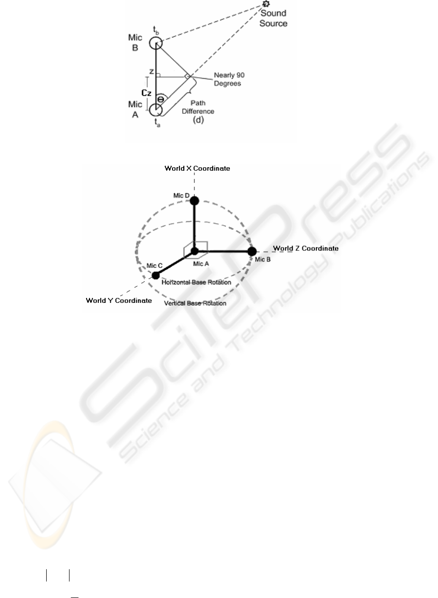
Figure 1: TDOA Estimation
Figure 2: Moving Microphone Array
arrays consist of two microphones kept in close
proximity. The sound sources are kept outside the
array. A microphone in the array has time delay
relationship with one another, dependent on the
location of sound source (Pirinen et al.,
2003)(Jahromi et al., 2003), as shown in Figure 1.
The distance from the sound source to the
microphones represent the time delays of the two
microphones in the model and path difference can be
determined by the time delay between microphones
in the array. Where
a
t and
b
t are the times received
at the observation points (Mic A and Mic B
repectively), d is the path difference between
a
t and
b
t , and
z
is the distance between two microphones
in the array.
In most cases, the angle opposite to both
microphones in the array is nearly 90º. Then, the
direction angle from the sound source and distance
to the furthest microphone can be determined as
follows:
ba ttd −= (1)
)(cos
1
z
d
−
=
θ
(2)
Because of the opposite angle to both
microphones in the array is not exactly 90°,
therefore, the direction of arrival may not be
accurately determined by Eq. (2). The remaining
problem of the TODA is that it could not accurately
determine the angle of sound source. This problem
also leads to the inaccuracy in distance
determination. We would like to propose A Model
for 3D Automatic Location Detection Based on
Sound Localization that can reduce the error in angle
detection on 3D space
.
3 PROPOSED MODEL
Auto Focus using Location Detection based on
Sound Localization comprises of a set of 4
microphones, as shown in Figure 2, in which one of
the microphones (Mic A) is at the center of the
model while the remaining microphones (Mic B,
Mic C , and Mic D) are located according to X, Y,
and Z axes and can horizontally and vertically
circulate around the center (Mic A). This circulation
ICINCO 2005 - SIGNAL PROCESSING, SYSTEMS MODELING AND CONTROL
240
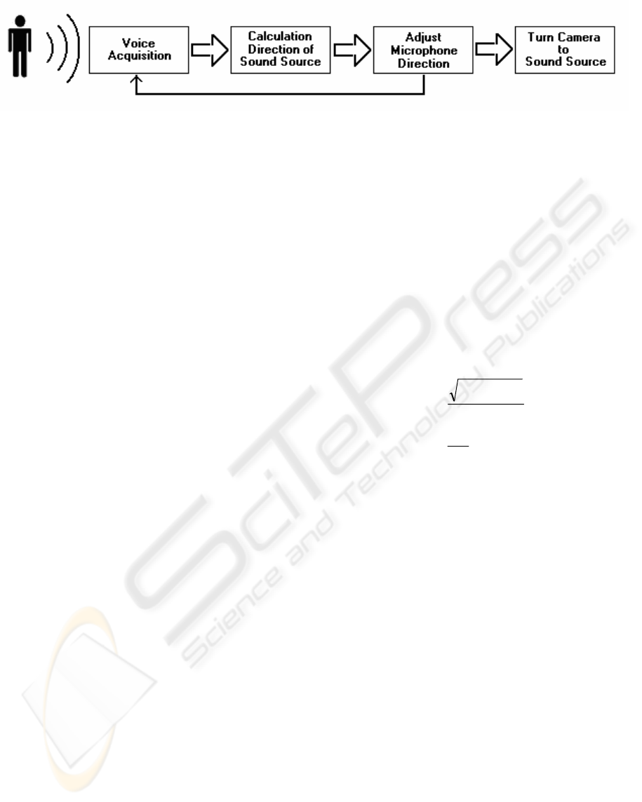
Figure 3: Algorithm of 3D Automatic Location Detection Based on Sound Localization
is to locate the sound source and read the angle of
sound source in horizontal and vertical directions on
ground based world coordinate. The algorithm for
detecting the sound source and rotating the video
camera is shown in Figure 3.
In our proposed model, we do not consider the
noise and reverberation of the sound. Therefore, we
assume that the sound travels in the air at constant
speed, 331.4 m/s. When the speaker generates the
sound, first of all, each microphone in the system
will detect the direction of that sound source. Then,
Mic B will be rotated according to
the position of
sound source in previous step, until the path
difference between Mic A and Mic B is equal to the
distance between two microphones in the array, i.e.
TDOA =
4.331/r where
r
is radius. The distance
from sound source towards the center of the model
can be calculated by the cross correlation among
these two microphone arrays. Finally, the video
camera is rotated regarding the direction angle and
focus on the speaker regarding the distance
parameter.
4 DIRECTION DETECTION
When the microphones detect the sound, time delay
of arrival (TDOA) is used to specify the rotation
direction of microphones in the model. Mic A is
fixed at the center of the array and Mic B points to
the 0º in the horizontal and vertical planes as shown
in Fig. 2. This model seperates a set of microphones
into 3 sections of microphone pair as follows: 1) Mic
A and Mic B: used to detect the sound source in Z
axis 2) Mic A and Mic C: used to detect the sound
source in X axis and 3) Mic A and Mic D: used to
detect the sound source in Y axis.
For each pair of microphones, Mic A is fixed at
the center of the array. According to Figure 1, time
delay between two microphones in each pair (d) can
be used to identify the distance from the center to
other microphones in the model by the following
formulas:
)()(
*
ABABZ
dCosC
θ
= (3)
)()(
*
ADADX
dCosC
θ
= (4)
)()(
*
ACACY
dCosC
θ
= (5)
where
C
Z
, C
X
, and C
Y
are the distance coordinates
of the simulated sound source from the Mic A at the
center to Mic B, Mic D, and Mic C respectively.
Then we will calculate the angle direction of the
sound source based on the model coordinates in
vertical (Mic A, B, D) and horizontal (Mic A, B, C)
directions as shown in Figure 4.
)(
22
1
)(
X
ZY
ABD
C
CC
TanOrg
+
=
−
ο
(6)
)(
1
)(
Z
Y
ABC
C
C
TanOrg
−
=
ο
(7)
where
Org°
(ABD)
is the vertical degrees of the model
and
Org°
(ABC)
is the horizontal degrees of the model.
Then we treat the values from the first
calculations
C
Z
, C
Y
, and C
X
to be the original
coordinates on World Coordinate –
Org
Z
, Org
Y
, and
Org
X
where Org
Z
, Org
Y,
and Org
X
are the
coordinate positons of the sound source in Z, Y, and
X axes respectively.
After we identify the angle of the sound source
in horizontal and vertical planes of the microphone
array, we start moving the microphone array by
pointing Mic B to the sound source according to the
angle values calculated by Eq. (6)-(7). Then restart
detecting the signal from sound source again by
recalculating the values of
C
Z
, C
Y
, and C
X
based on
the current positions of microphones. Then compare
the coordinates of the current positions of
microphones to the World Coordinate by referring to
the rules of 3-D rotation on X and Y axes as follows:
)(*
)(ABC
OrgCos
Z
C
Z
TempC °=
)(*)(
)(ABC
OrgSin
Y
C °−+
(8)
3D AUTOMATIC LOCATION DETECTION BASED ON SOUND LOCALIZATION
241
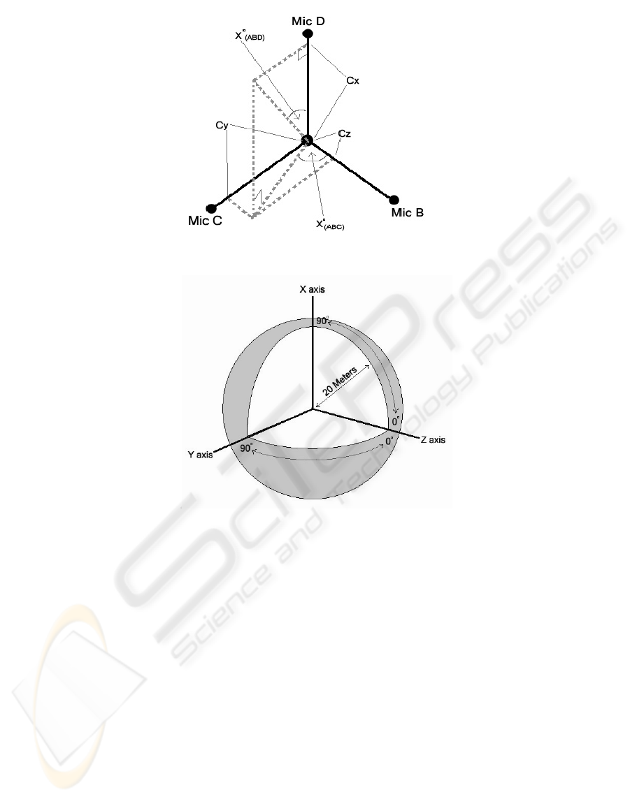
Figure 4: Microphone Coordinate Base
Figure 5: Experimentation on Angle Determination
)(*)(
)(ABCZY
OrgSinCNewC °−=
)(*)(
)( ABCY
OrgCosC °−+
(9)
))(*)(
)( ABDXX
OrgCosCNewC °−−=
)(*
)( ABDZ
OrgSinTempC °−+
(10)
)(*
)( ABDXZ
OrgSinCNewC °−=
)(*
)( ABDZ
OrgCosTempC °−+
(11)
where
NewC
X
, NewC
Y
, and NewC
Z
are the values of
the new coordinates XYZ based on the World
Coordinate.
Then we calculate the Original Degrees of
Microphone Array Rotation by changing the values
of
C
Z
, C
Y
, and C
X
to NewC
Z
, NewC
Y
, and NewC
X
.
Then we detect the signal from sound source
repeatedly until the path different between Mic A
and Mic B is equal to the physical distance value
between Mic A and Mic B. The final value of
Org°
(ABC)
and Org°
(ABD)
is the direction of the
detected sound source.
5 EXPERIMENT AND RESULTS
In our experiment, we wrote a C program to
simulate the experiment on Pentium IV 1.4 GHz
with 256 MB of RAM. This simulation program
receives the distance and angle values from static
sound source towards the center of the model (Mic
A). Based on that reference point, the simulation
program will evaluate the correctness of angle
determination in various distances of the static sound
source from 5 to 20 meters correlated with various
diretions on vertical and horizontal planes.
We randomly located the static sound source in
various positions and calculated the error in terms of
difference in degrees. The average error values are
shown in Table 1.
ICINCO 2005 - SIGNAL PROCESSING, SYSTEMS MODELING AND CONTROL
242
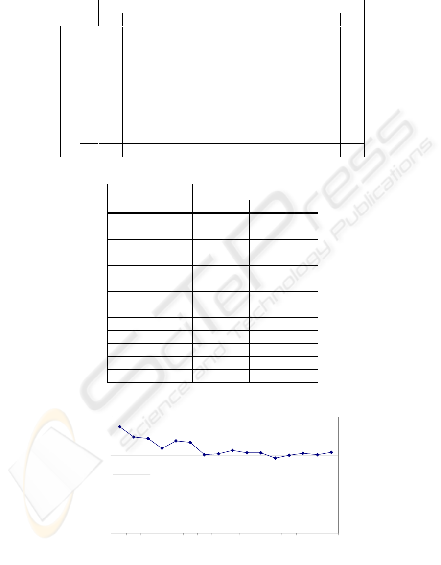
Table 1: Average Error of Angle Detection in Various Direction of Sound Sources
Horizontal Distance of Sound Source (from 0 - 90 degrees)
0 10 20 30 40 50 60 70 80 90
0
0.00 7.69 8.33 9.66 6.84 7.36 3.75 4.79 4.17 0.22
10
7.00 7.59 7.59 8.35 7.49 18.42 14.21 5.56 3.71 0.22
20
6.68 7.84 14.38 7.78 6.61 6.79 6.49 4.93 4.56 0.22
30
6.90 8.26 12.19 8.87 5.12 5.87 4.86 6.25 6.51 0.22
40
5.54 8.43 18.13 7.87 6.18 5.01 5.67 5.11 9.28 0.22
50
5.71 9.54 7.67 6.31 6.42 5.15 5.95 11.13 10.13 0.22
60
6.63 11.08 5.68 6.15 5.71 14.87 3.69 14.07 8.60 0.22
70
5.45 9.71 4.75 6.03 2.66 4.15 4.50 24.63 24.55 0.22
80
7.16 18.71 6.22 5.56 10.25 6.79 5.17 29.20 31.05 0.22
Vertical Direction of Sound Source
(from 0 – 90 degrees)
90
0.22 16.41 10.59 5.90 5.62 5.59 8.40 32.72 31.92 0.22
Table 2: Some of the Original X,Y,Z Coordinates, Determined X,Y,Z Coordinates, and Error in Degrees
Original Sound Source
(Meters)
Determined Sound
Source (Meters)
X Y Z X Y Z
Error
Degree
0.00 0.00 17.00 0.00 0.00 17.00 0.00
2.59 0.00 9.66 1.35 0.26 9.90 7.38
10.61 0.00 10.61 10.61 0.02 10.61 0.09
12.00 0.00 0.00 12.00 0.02 0.02 0.14
0.00 4.10 11.28 0.16 2.58 11.72 7.61
0.00 16.00 0.00 0.02 16.00 0.02 0.08
11.26 3.25 5.63 11.28 4.20 4.90 5.29
2.07 5.92 4.97 0.49 5.87 5.41 11.75
11.57 10.56 8.86 12.73 10.49 7.20 6.46
7.71 8.88 2.38 6.99 9.44 2.47 4.39
9.85 1.68 0.45 8.71 -3.63 3.31 35.76
14.77 2.59 0.23 10.00 10.91 2.47 38.32
14.77 2.60 0.00 13.78 0.63 5.88 24.19
Figure 6: Average Error in Various Source Distances (5-20 m.)
0
2
4
6
8
10
12
56
789
10 11 12
13 14
15 16
17 18
19 20
Meters
Degree
s
3D AUTOMATIC LOCATION DETECTION BASED ON SOUND LOCALIZATION
243

Table 1 shows that when the sound source is in
range of 70-90 degrees in vertical direction and in
range of 70-80 degrees in horizontal direction the
error rate will be high dued to the closeness of the
sound source to the top of the model in vertical
direction introduces the error in angle determination
in horizontal direction.
Table 2 shows that when the sound source lies
only on the X, Y, or Z coordinate the error in angle
determination is very low. This table also shows that
if the sound source is close to the model in Z
coordinate and is further away from the model on X
coordinate the error in angle determination is high.
Figure 6 shows that the average error in angle
determination is approximately to 10 degress from
the sound source. When the sound source is in the
range of 5-10 meters away from the model the
average error rate will be higher. If the sound source
is further than 10 meters from the model the error
rate will decrease.
6 DICUSSION AND FUTURE
RESEARCH
TDOA estimation assumes that the path difference
between two microphones will produce the
perpendicular angle to either microphone in the
model. The distributed microphone arrays can be
used to accurately estimate the angle direction from
sound source toward the model (Aarabi, 2003). The
higher the number of microphones in the model or
the number microphone arrays, the longer
processing time will be. These distributed
microphone arrays are most effective when used in
2D environment.
In our proposed model, all microphones except
one at the center can be rotated to the direction of
the sound source in 3D environment. The model will
be moved in either vertical or horizontal direction at
the first time. Then, the model will be moved again
in other direction to identify the source source. This
model is less effective when the sound source is
located more than 70 degress in both vertical and
horizontal directions. According to the methodology
that the model will move toward to the sound source
then the limitation is that if the sound source keeps
moving, the model may not stop the processing to
detect the exact location of the sound source. Our
future research will perform the experiment on
moving sound source, reduce the error rate and take
the distance determination into consideration.
ACKNOWLEDGEMENT
We would like to thank Assumption University for
this research funding.
REFERENCES
Onishi M., Kagebayashi T., and Fukunaga K., 2001.
Production of video images by computer controlled
cameras and its application to TV conference system.
In Proc. IEEE International Conference on Computer
Vision and Pattern recognition.
Pirinen T., Pertila P., and Visa A., 2003. Toward
intelligent sensors – reliability for time delay based
direction of arrival estimates. In Proc. IEEE
International Conference on Acoustics, Speech, and
Signal Processing.
Rabenstein R. and Strobe N.K., 1999. Classification of
time delay estimates for robust speaker localization. In
Proc. IEEE International Conference on Acoustics,
Speech, and Signal Processing.
Jahromi O. and Aarabi P., 2003. Time delay estimation
and signal reconstruction using multi-rate
measurement. In Proc. IEEE International Conference
on Acoustics, Speech, and Signal Processing.
Aarabi P., 2003. The fusion of distributed Microphone
arrays for sound localization. In International Journal
on Applied Signal Processing.
Aarabi P. and Mahdavi M., 1996. The relation between
speech segment selectivity and time-delay estimation
accuracy. In Proc. IEEE International Conference on
Acoustics, Speech and Signal Processing.
Brandstein M.S. and Silverman H.F., 1996. A robust
method for speech signal time-delay estimation in
reverberant rooms. In Proc. IEEE International
Cpnference on Acoustics, Speech, and Signal
Processing.
Knapp C.H. and Carter C.G., 1976. The generalized
correlation method for estimation of time delay. In
IEEE Transaction on Acoustics, Speech and Signal
Processing.
Porntrakoon P., Kesarat D., Daengdej J., 2004. Auto
Focus using Location Detection based on Sound
Localization. In Proc. ASM-2004, International
Conference on Applied Simulation and Modelling.
ACTA Press.
ICINCO 2005 - SIGNAL PROCESSING, SYSTEMS MODELING AND CONTROL
244
