
A GRAPHICAL INTERFACE BASED ON GRAFCET FOR
PROGRAMMING INDUSTRIAL ROBOTS OFF-LINE
Gustavo V. Arnold
∗
, Pedro R. Henriques
Department of Informatics, University of Minho
Braga, Portugal
Jaime C. Fonseca
Department of Industrial Electronic, University of Minho
Braga, Portugal
Keywords:
Compilers, Graphical Interface, Industrial Robots Programming Language, Code Generator.
Abstract:
This paper presents the current development stage of our approach to industrial robot programming, that is
the graphical interface for our environment, that is based on the well-known Grafcet. Our approach focus on
the modelling of the system, rather than on the robot. So, it will improve the programming and maintenance
tasks, allowing the reuse of source code.
1 INTRODUCTION
Today, there are basically two ways for programming
industrial robots: (1) by the use of the industrial ro-
bot programming language (IRPL); (2) or by the use
of off-line programming environments (OLPE). How-
ever, both of them have their own drawbacks:
1. although the forerunner languages, such as AML
(Taylor et al., 1982) or AL (Mujtaba et al., 1982),
have now been superseded by elaborated robot lan-
guages, like ABB Rapid (Automation, 1994), they
require detailed description of the motion of every
joint in the mechanism in order to execute a de-
sired movement; they require specialized knowl-
edge of the language; the robot programs have lim-
ited portability, and significant investment must be
made when changing or acquiring a new robot type
or simply when upgrading a new controller from
the same vendor.
2. the most recent off-line programming environ-
ments (for instance, Workspace) do not address the
issue of sensor-guided robot actions; and they are
limited to a robot motion simulator, which provides
no advanced reasoning functionality, nor flexibility
in the tasks.
According to some principles of software engineer-
ing and programming languages evaluating criteria
∗
Gustavo Arnold is a professor at Universidade Cat
´
olica
do Salvador - Brasil, and is temporarily at Universidade do
Minho to get his PhD degree, supported by a FCT scholar-
ship.
(Sebesta, 1999), it is possible to see that these devel-
opment environments do not attend the user needs, as
can be seen on figure 1.
Principles OLPE IRPL
User-friendly YES NO
Source Code
Portability YES NO
Expressiveness NO YES
Environment
interaction NO YES
Specification
close to the NO NO
problem
Reusability NO NO
Figure 1: Principles of software engineering and program-
ming languages that must be supported by the programming
environments
So, we proposed an integrated, formal and high-
level approach to industrial robot programming
(Arnold et al., 2003), that will attend these users de-
sires. One component of this approach is a friendly
graphical interface, based on the Grafcet specification
diagram. This interface is responsible not only for fa-
cilitating the programming task, but also to translate
this diagrammatic specification into languages that
belong to different levels of our approach. This in-
terface is user-friendly, the program specification is
close to the problem (instead of close to the robot),
and allows environment interaction (which means that
113
V. Arnold G., R. Henriques P. and C. Fonseca J. (2005).
A GRAPHICAL INTERFACE BASED ON GRAFCET FOR PROGRAMMING INDUSTRIAL ROBOTS OFF-LINE.
In Proceedings of the Second International Conference on Informatics in Control, Automation and Robotics - Robotics and Automation, pages 113-118
DOI: 10.5220/0001168501130118
Copyright
c
SciTePress
our implementation will allows the development of
closed-loop systems). It is also expressive, but it still
can be more, depending on the other components that
are under construction. The source code portability
will also be achieved at the end of this implementa-
tion. And the reusability will also be achieved when
extend the graphical interface.
The aim of this paper is to discuss that graphical in-
terface based on the Grafcet, and the associated trans-
lator to RS language (Toscani, 1993) (a reactive sys-
tems programming language).
In the following sections, the most relevant theoret-
ical aspects (like our approach to industrial robot pro-
gramming, in section 2, and the Grafcet in section 3),
and the components already implemented (the graph-
ical interface in section 4, and the translator in section
5) are presented. At the end (section 6), appear the
conclusions and future works.
2 OUR APPROACH TO
INDUSTRIAL ROBOT
PROGRAMMING
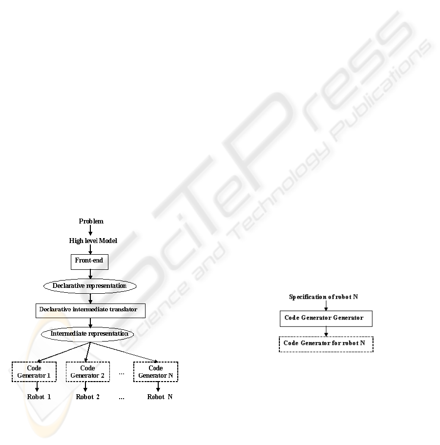
Our approach is described diagrammatically in figure
2. It should be supported by the following languages
and tools that compose the architecture we want to
defend:
Figure 2: Proposed approach to industrial robots program-
ming.
• a truly high level and declarative language (Grafcet,
RS)
• an easy-to-use front-end
• an intermediate representation (DIR)
• the translators to RS and to DIR
• the code generator
• an automatic generator of the robot code generators
• a robot specification language
At the top, there is the problem to be solved. It will
be used an adequate modelling technique, responsible
for decompose the problem into simple problems, that
would be easily programmed; formal models are em-
ployed to describe data structures and operations nec-
essary to solve the subproblems. To describe formally
the overall problem and the subproblems, a truly high
level language, close to the specification instead of the
robot, should be used. Then we advocate the use of
an easy-to-use compiler front-end, like Grafcet, that
can interpret the specification language and generate
a declarative description, that can be translated into
an intermediate description for the program specified.
An intermediate representation is used because the
front-end must be focused on the specification of the
problem, and not on the robot. So, there will be an-
other component responsible for translating this in-
termediate code into the code of a robot. Because this
compiler back-end is specific for a single robot, it is
necessary to have a lot of back-ends, each of them
adapted to a specific target (robot’s architecture and
machine code). To create these code generators, an
automatic generator will be used, as can be seen in
figure 3. This tool, based on the known intermedi-
ate representation, and on the robot specification, that
must be included someway, will produce an optimal
code generator for the specified robot.
The main objective of this approach is to make the
programming task easy, with the possibility of reusing
the source code to program different industrial robots,
allowing to explore their potentialities.
Figure 3: Automatic generator of code generators.
3 GRAFCET
Because Grafcet (Telemec, 1982) is a well known
specification diagram for industrial automation appli-
cations, it was decided to use a graphical interface that
should looks like the Grafcet, as told above.
So before describing the FE interface built, we dis-
cuss the basic concepts that Grafcet uses to represent
automatisms, that are (Grafcet, 2000):
ICINCO 2005 - ROBOTICS AND AUTOMATION
114
• Step, represents a partial state of system, in which
an action was performed. The step can be active or
idle. The associated action is performed when the
step is active, and remains asleep when the step is
idle;
• Transition, links a precedent step (one or several)
to a consequence step (one or several), and repre-
sents the actions flow. It describes a state change.
Changing is under the control of two conditions:
1. every step previous to the transition must be ac-
tive (and the actions executed),
2. a boolean condition associated with the transi-
tion, must be true.
4 GRAPHICAL INTERFACE
The interface that was implemented represents all the
concepts and features present on a Grafcet diagram,
and have a similar appearance. An example of this
interface can be seen on figure 4
On this example, a robot can move throw three
points, P1, P2 and P3 (P2 at the center, P1 to the left,
and P3 to the right), and at each moment can only be
in one of these positions. There are three buttons, re-
sponsible for indicating the point to where the robot
must make a transfer. When one button is pressed, the
robot must do the following steps:
• Close the gripper;
• Make a transfer to the a left or to the right, depend-
ing on the pressed button and the current position;
• Open the gripper when arriving at the desired posi-
tion.
Based on Grafcet, this example is implemented in
the following way: The step E1, that is the initial one,
represents the rest state for the robot. At this moment,
the robot can be in any of the P1, P2 or P3 positions.
When a button (D1, D2 or D3) is pressed, a position is
selected; then the robot must make a transfer from its
current position to the desired one. The three possibil-
ities (D1 pressed when the robot is on P2 or P3, etc)
are described by the three transitions below E1. The
occurrence of one of these possibilities implies a step
changing to E2, E3 or E4. At any of these steps, the
robot must close the gripper (Close G). After receiv-
ing the information that the gripper is closed (GC),
there is another step changing, to E5, E6, E7, or E8.
At any of these steps, the transfer is done and the ro-
bot moves to the left (TL) or to the right (TR). Steps
E6 and E7 will be chosen depending also on the ini-
tial position of the robot (P3 or P1), because P2 is the
central position. So if the robot is at P1, it must move
to the right, and if it is at P3 it must move to the left.
When the robot arrives at the desired position (AP1,
AP2 or AP3), another step changing is done, and the
robot must open de gripper (Open G). When the grip-
per is opened (GO), the robot returns to its rest state,
the step E1 (although, the robot stays at this current
position).
In the rest of this section, we explain how the
Grafcet constructors were implemented in our editor.
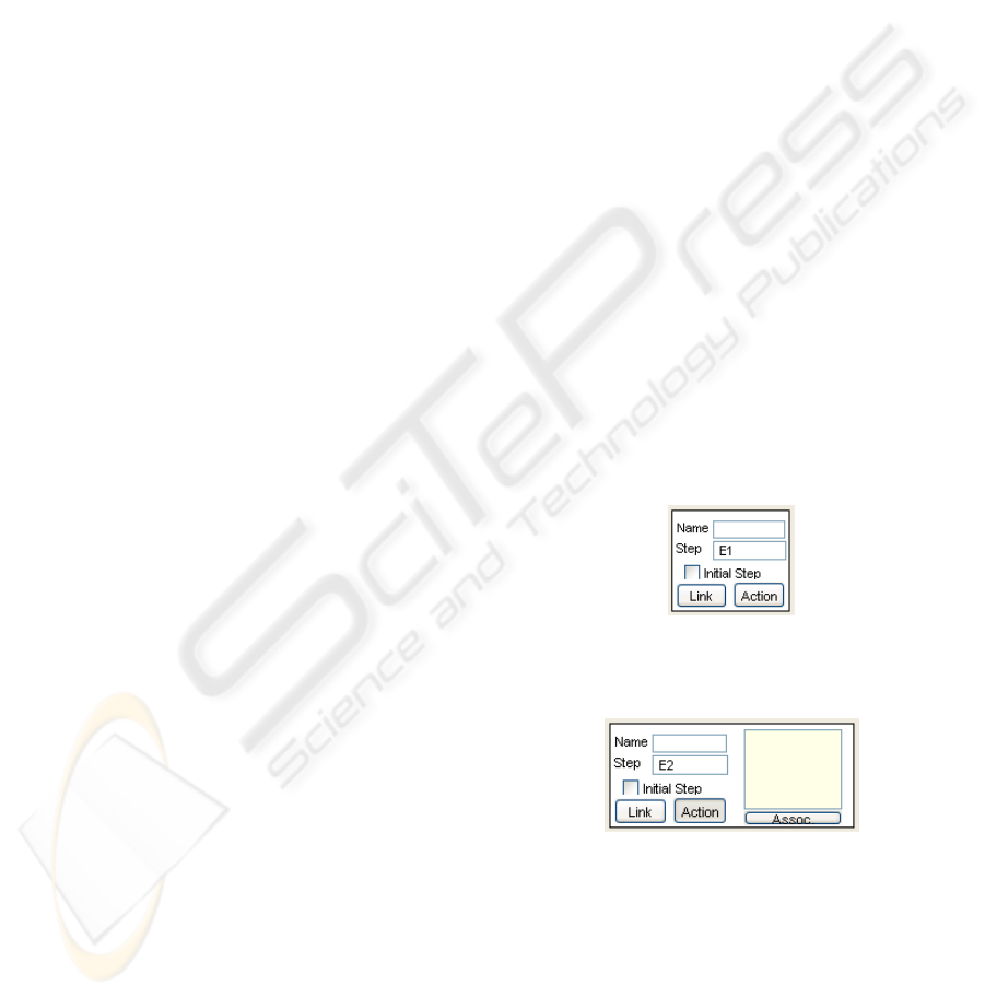
4.1 Steps
The steps are represented as squares. Inside there are
two fields: the number of this step, that is a manda-
tory field (a step number is generated automatically,
but the user can modify it); and the name of the step,
that is an optional field (the user can name the step to
make it easy to understand its main goal). There is
a checkbox, called initial, that indicates if this is an
initial step. If it is, the square border becomes thicker.
After inserting a new step (square) into the diagram,
the editor offers two more options, that are the two
buttons inside the square: the first one is the link but-
ton, responsible for linking this step to the next tran-
sition(s); the last one is the action button, responsible
for associating actions to this step (figure 5). When
this action button is pressed, the square is augmented,
at the right side, and a text box appears, where the
user can enter the actions code. The associate button
inside this new right box allows to store these actions
(when they are written) associated to the current step
(figure 6).
Figure 5: Step graphic representation.
Figure 6: Step and actions graphic representation.
Each action should be written considering the fol-
lowing grammar, which makes possible to represent
all the conditions and actions proposed by Grafcet:
actions -> ( "(" condition ")"
"{" (action ";")+ "}" )+
condition -> cond | condition op cond
cond -> iv | ˜iv | n_step
op -> "," | "|"
action -> command
A GRAPHICAL INTERFACE BASED ON GRAFCET FOR PROGRAMMING INDUSTRIAL ROBOTS OFF-LINE
115
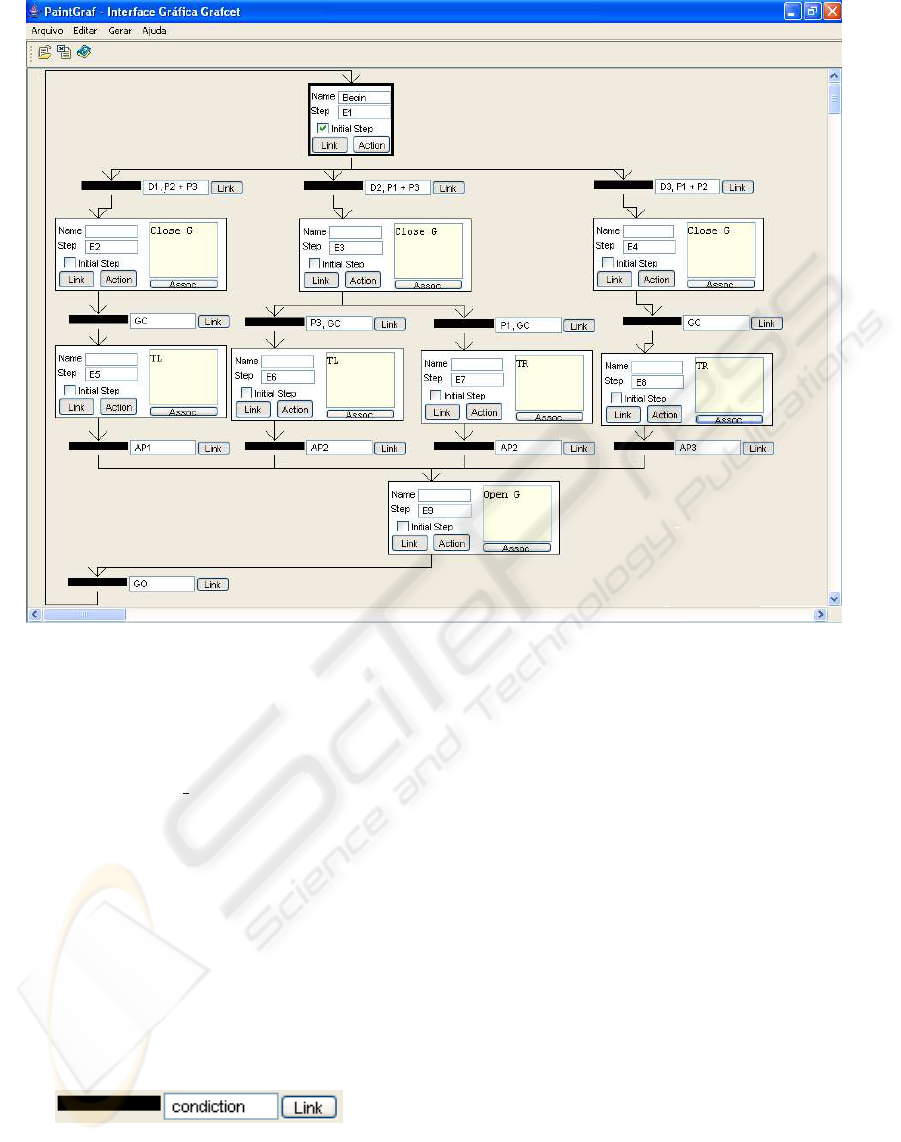
Figure 4: Graphical interface based on Grafcet.
Conditions are written inside ”()” and they are op-
tional; iv corresponds to an input variable that must
be on, while the ∼iv corresponds to an input variable
that must be off, and n
step corresponds to steps
that must be active. If a condition is satisfied, the ac-
tion(s) can be executed. If there are more then one
action to be executed for one condition, these actions
must be written inside ”{}”. It is necessary to use a
”;” at the end of each action.
4.2 Transitions
Each transition is represented by a thick horizontal
line, followed by the condition field, that must be
written by the user, and by a link button, responsible
for linking this transition to the next step(s) (figure 7).
Figure 7: Transition graphic representation.
Each condition should be written considering the
following grammar, which makes possible to repre-
sent all the functions proposed by Grafcet:
condition -> expr | condition op expr
expr -> v "+" | v "-" | time |
"(" conditon ")"
time -> t "/" n_step "/" seconds
op -> "," | "|"
where v+ corresponds to set the variable v to 1,
while the v- corresponds to reset the variable v to 0.
4.3 Alternatives and Simultaneous
Sequences
The sequences are generated automatically by the sys-
tem. The user must only link the steps to the transi-
tions and vice-versa. If the user wants to link one
transition to more than one step, a double line is pre-
sented, to show that this is the beginning of a simul-
taneous sequence. Also, if the user links more than
one step to only one transition, a double line is also
presented, but to indicate that this is the end of a si-
multaneous sequence. The other links are treated as
alternative sequences. Each object can be moved to
any position in the window, without loosing the links.
ICINCO 2005 - ROBOTICS AND AUTOMATION
116

5 TRANSLATOR
At this moment, there is only one translator ready,
that is the one that translates the Grafcet graphical
representation into an RS program. The Grafcet el-
ements implemented on the graphical interface were
discussed on previous sections, while the RS lan-
guage and automaton can be seen on(Toscani, 1993)
The variables are defined previously by the user,
but the input, output and internal signals are detected
automatically. The RS internal signals correspond to
the steps, the RS input signals are detected during the
parsing of the conditions (from actions and from tran-
sitions), and the RS output signals are detected during
the parsing of the actions that must be executed.
Some auxiliary RS internal signals are also gener-
ated, if there are more then one action associated to
one condition or step. They are generate to grant the
sequential execution of each of these actions.
All the conditions are written using the infix nota-
tion. So, a boolean expressions analyzer was created.
It is also possible to call the RS compiler, to trans-
late this RS program into an automaton.
To illustrate the idea, figure 8 shows the generated
RS program for the sample Grafcet specification pre-
sented in figure 4. The up(signal) is responsible for
activating an internal signal, and the emit(command)
is responsible for sending an specific command to the
environment.
5.1 Steps
Each step of Grafcet is treated as an internal signal of
the RS language. So, for each step an internal signal
is created, if it still does not exist, and included at the
module header of the RS program. If the step is a ini-
tial one, it is added a command up(this step)
at the initially sentence of the module header.
This means that the respective internal signal will be
activated at the beginning, starting the automaton ex-
ecution at this step. The rules are executed if the sig-
nals (internal or input) on the left side of the rule are
on. The internal signals can be signalized internally,
while the input ones are set by the external environ-
ment.
If the step contains some action, it will be parsed
to detect the actions and their respective conditions,
if they exist. For each action, an output signal is cre-
ated and inserted at the module and program headers,
and an emit(this action) command is added
at the point where this action should be executed. The
output signals are responsible for sending commands
to the external environment (as a consequence of the
emit command).
rs_prog testando_programaRS:
input : D1,P2,P3,GC,AP1,GO,D2,P1,
AP2,D3,AP3;
output: Close G, TL, Open G, TR;
module testando_modulo:
input : D1,P2,P3,GC,AP1,GO,D2,
P1,AP2,D3,AP3;
output : Close G, TL, Open G, TR;
t_signal:E1,E2,E5,E9,E3,E6,E7,E4,E8;
initially: up(E1);
D1,P2,E1 ==> emit(Close G), up(E2);
D1,P3,E1 ==> emit(Close G), up(E2);
GC, E2 ==> emit(TL), up(E5);
AP1, E5 ==> emit(Open G), up(E9);
GO, E9 ==> up(E1);
D2,P1,E1 ==> emit(Close G), up(E3);
D2,P3,E1 ==> emit(Close G), up(E3);
P3, GC, E3 ==> emit(TL), up(E6);
AP2, E6 ==> emit(Open G), up(E9);
P1, GC, E3 ==> emit(TR), up(E7);
AP2, E7 ==> emit(Open G), up(E9);
D3,P1,E1 ==> emit(Close G), up(E4);
D3,P2,E1 ==> emit(Close G), up(E4);
GC, E4 ==> emit(TR), up(E8);
AP3, E8 ==> emit(Open G), up(E9);
end module;
end rs_prog.
Figure 8: Example of a generated RS program.
5.2 Transitions
Each Grafcet transition is parsed to detect the condi-
tions, the kind of each element (input variables, auxil-
iary variables, steps), and to analyze the boolean con-
ditions that may exist. Each input variable is added as
an input signal (if it does not exist) at module and pro-
gram headers; each step is added as an internal signal
at module heading (if it does not exist). The auxil-
iary variables were added directly by the user, when
using the graphical interface, but they are included on
the respective rule, to perform the correct behavior.
All of these elements will be included on the left side
of the respective rule, with the internal signals corre-
sponding to the steps that precede this transition.
5.3 Alternatives and Simultaneous
Sequences
The alternative sequences are detected and included
at the end of each rule, by the use of the up(next
step) command. This command is responsible for
activating the internal signal associated to the next
step that must be evaluated. There is no problem in
closing this kind of sequence, because there is no syn-
chronization between the steps of this sequence.
The simultaneous sequences are treated at the same
way, but because one transition will trigger more than
A GRAPHICAL INTERFACE BASED ON GRAFCET FOR PROGRAMMING INDUSTRIAL ROBOTS OFF-LINE
117

one step, it will be included more than one up(next
step), to activate all the internal signals that are as-
sociated to the next steps. Because it is necessary to
synchronize the last steps at the end of this sequence,
each of these last steps will create an internal signal
and activate it. The following step will only be ex-
ecuted if all the internal signals from the precedent
steps are active.
5.4 Basic Algorithm
This section presents the basic algorithm of the trans-
lator described. We think that the algorithm is self-
explanatory and do not deserve more comments.
for each initial step {
add this step as an internal signal;
add up(this step) at initially
sentence;
for each following transition
{
execute the
Transition_evaluating_function;
}
}
Transition_evaluating_function:
if this transition was not evaluated {
add its elements as variables, input
and internals signals;
evaluate its boolean expression;
create the rules:
{
each element will be on the left
side;
the actions of each next step are
evaluated:
{
their conditions are also
included on the left side;
the actions are included at the
right side by the
emit(action) commands;
}
add this next step as an internal
signal;
add the up(next step) command on
the right side;
go to the following transitions for
this next step and execute the
Transition_evaluating_function;
}
}
6 CONCLUSIONS
This paper presented a graphical interface for high-
level industrial robot programming, based on the
Grafcet; it was also introduced the respective trans-
lator from Grafcet to RS language. This work is part
of an approach to industrial robot programming, that
will cover all the stages of the programming task,
from the modelling of the system until the robot code
generation.
Both the translator and the Graphical interface were
developed using Java language. Java was chosen be-
cause the goal of this project is to grant portability for
the source code. So, it is important to use a language
that is also platform independent.
As Grafcet is completely implemented, the pro-
gramming task becomes easier. And as the RS trans-
lator generates an efficient and simple automaton, the
generated code must also be efficient and simple, like
the one presented at (Piola, 1998).
The next step is the development of a translator
from the automaton RS to DIR, or from the automa-
ton RS to an industrial robot language. Then we will
address the development of the code generator gener-
ator.
By now, our approach satisfies the following cri-
teria of figure 1: user-friendly, expressiveness, en-
vironment interaction, and specification close to the
problem. When the implementation finishes, all of
the principles in figure 1 will be granted.
REFERENCES
Arnold, G. V., Henriques, P. R., and Fonseca, J. C. (2003).
A development approach to industrial robots program-
ming. In Proceedings of the 11th International Con-
ference on Advanced Robotics, volume 1, pages 167–
172, Coimbra, Portugal. Institute for Systems and Ro-
botics, University of Coimbra.
Automation, A. F. (1994). Rapid Reference Manual 3.0.
Grafcet (2000). Grafcet homepage.
http://www.lurpa.ens-cachan.fr/grafcet.html.
Mujtaba, M. S., Goldman, R., and Binford, T. (1982). Stan-
ford’s al robot programming language. Computers in
Mechanical Engineering.
Piola, S. J. (1998). Uso da linguagem rs no controle do
rob
ˆ
o nachi sc15f. Trabalho de Conclus
˜
ao de Curso de
Graduac¸
˜
ao, Departamento de Inform
´
atica, UCS, Ca-
xias do Sul, Brasil.
Sebesta, R. W. (1999). Concepts of programming lan-
guages. Addison Wesley Longman, Inc., 4nd edition.
Taylor, R. H., Summers, P. D., and Meyer, J. M. (1982).
Aml: a manufacturing language. The International
Journal of Robotics Research, 1(3).
Telemec (1982). O Grafcet – Diagrama Funcional para
Automatismos Sequenciais. Portugal.
Toscani, S. S. (1993). RS: Uma Linguagem para
Programac¸
˜
ao de N
´
ucleos Reactivos. Tese de doutora-
mento, Depto de Inform
´
atica, UNL, Lisboa, Portugal.
ICINCO 2005 - ROBOTICS AND AUTOMATION
118
