MODELLING AND LQ-BACKSTEPPING CONTROL FOR A
QUADROTOR
Sébastien Belin, Mathieu Carton, Fabien Macaire
SUPAERO, 10 avenue Edouard Belin, 31055 Toulouse, France
Keywords: UAV, VTOL, quadrotor, LQ, Backstepping.
Abstract: Thanks to significant advances during the last decades in the miniaturized robotic area, many Unmanned
Aerial Vehicle (UAV) projects were launched. Among them, the QuadriXflyer is an UAV quadrotor
designed to evolve autonomously between waypoints given by an operator before flight. In this paper, we
propose a modelling and a new hybrid control approach for the QuadriXflyer; a controller integrating the
advantages of a Linear Quadratic (LQ) and those of a backstepping approach allowing to compensate the
nonlinearities of the system. With this new approach, the gravity will be compensated directly without time
delay. Robustness of the controller is then studied to ensure the stability of the quadrotor to exogenous
(wind for example) and internal (noise on measurements, uncertainties on the inertia for example)
perturbations.
1 INTRODUCTION
With reduction in cost and progress in miniature
technology, many studies have been launched in
order to build autonomous miniaturized flying
robots (Bouabdallah, Murrieri, Siegwart, 2004,
Altuğ, Ostrowki, Mahony, 2002, Hamel, Mahony,
Lozano, Ostrowski, 2002, Pounds, Mahony,
Gresham, 2004, Bouabdallah, Siegwart, 2005,
Fantoni, Antoni, Lozano, Nazenc, 2001, Praly,
Ortega, Kaliora, 2000). The purpose of this study is
to present a modelling and a new hybrid control
method based on LQ for the linear part and
backstepping for the non linear part of the control,
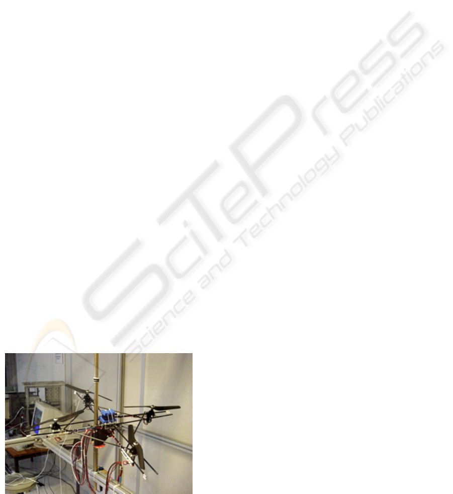
for an autonomous four-rotor helicopter. The
application has been realized on a quadrotor named
QuadriXflyer (figure 1) and composed by a frame
with four carbon rods setting up a straight cross. An
actuator is fasten at the end of each rob and is
constituted by a propeller, a reducer and a direct
current electric motor. Each propeller is driven in
rotation by its motor via a reducer. The
QuadriXflyer has two propellers with a right thread
and two propellers with a left thread. This is useful
for the yaw stabilization. The aim of this quadrotor
is to evolve autonomously between waypoints given
by an operator before flight.
2 MODELLING
To validate the control laws, a non-linear dynamic
simulation model was created using Simulink. This
model takes into account the QuadriXflyer as a rigid
frame mechanical system, actuators (propellers +
motors + reducers), gyroscopic and thrusts efforts.
The other assumptions are that the only
aerodynamics effects are propellers thrusts and drag
torques. Previous publications (Bouabdallah,
Murrieri, Siegwart, 2004, Hamel, Mahony, Lozano,
Ostrowski, 2002, Pounds, Mahony, Gresham, 2004)
have presented models where propellers axes and z
QuadriXflyer axe were parallel.
Figure 1: The QuadriXflye
r
134
Belin S., Carton M. and Macaire F. (2005).
MODELLING AND LQ-BACKSTEPPING CONTROL FOR A QUADROTOR.
In Proceedings of the Second International Conference on Informatics in Control, Automation and Robotics - Robotics and Automation, pages 134-139
DOI: 10.5220/0001177501340139
Copyright
c
SciTePress
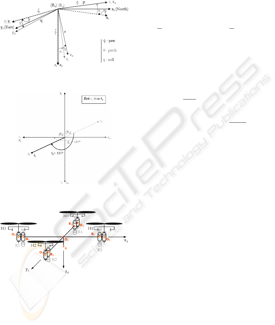
Euler angles ψ, θ, φ, define the rotations between
Earth frame (Ro) and QuadriXflyer frame (Rd):
Two angles define the rotations between each
actuator own frame (Ri) and frame (Rd).
The figure below shows the general QuadriXflyer
cinematic diagram:
Our generic model accepts propellers tilt to simulate
lacks of precision or to develop news control
methods using four tilted propellers running in the
same direction. This new control method (not
developed in this paper) will allow to control the
yaw with tangential forces created by propellers tilt
instead of use the propellers drag torques
differences.
The simulator consists in two main Simulink blocks:
one calculates the efforts provided by the actuators
to the main body and the other integrates these
efforts to calculate linear positions of the center of
gravity X, Y, Z and Euler angles ψ, θ, φ.
For a propeller with angular velocity w
i
, thrust and
drag torque are modeled by:
F
i
=
2
1
.ρ. P
z
.(w
i
)
2
C
i
=
2
1
.ρ. M
z
.(w
i
)
2
,
Where P
z
and M
z
are non-sized thrust and drag
torque coefficients.
The first Simulink block contains a direct current
electrical motor model based on the equations
below:
()
() () ()
m
dI t
Ut RIt L E t
dt
=+ +
() ()
mi
m
Et Kwt=
() () () ()
memi
EtIt C twt=
()
() ()
ri
em
dw t
J
tCt
dt
=
The torque applied to the main body, depends on
motor, reducer, and propeller inertias. Therefore,
this torque value is calculated for each actuator
using rotor and propeller dynamic moments and C
i
propeller’s drag torque:
The second Simulink block calculates the whole
torques applied to the main body at QuadriXflyer
center of gravity. Using the results above, and
applying the dynamic fundamental principle. Linear
accelerations, p, q, r angular velocities and ψ, θ, φ
are calculable:
where
T
od
1
oddo
M M M ==
−
and :
(
)
(
)
(
)
.,/0,/0
iiiiiii
Oi
Ma dCz BR OH
δδ
→= − −
G
G
G
G
4
1
4
1
4
1
0
=.,
0
.
ix
i
iy
do
i
i
iz
X
F
mMF
Y
F
mg
Z
=
=
=
⎡⎤
⎡⎤
⎢⎥
⎢⎥
⎡⎤
∑
⎢⎥
⎢⎥
⎢⎥
⎢⎥
⎢⎥
⎢⎥
⎢⎥
⎢⎥
⎢⎥
+
∑
⎢⎥
⎢⎥
⎢⎥
⎢⎥
⎢⎥
⎢⎥
⎢⎥
⎢⎥
⎢⎥
∑
⎢⎥
⎢⎥
⎢⎥
⎣⎦
⎢⎥
⎢⎥
⎢⎥
⎢⎥
⎣⎦
⎣⎦
cc cs -s
ssc cs sss cc sc
csc s css sc cc
od
M
s
θψ θψ θ
φ
θψ φψ φθψ φψ φθ
φ
θψ φψ φθψ φψ φθ
⎡
⎤
⎢
⎥
=− +
⎢
⎥
⎢
⎥
+−
⎣
⎦
MODELLING AND LQ-BACKSTEPPING CONTROL FOR A QUADROTOR
135

With
sin( ) cos( )
0
cos( ) cos( )
0 cos( ) sin( ) .
1 tan( ).sin( ) tan( ).cos( )
()
p
q
r
Rd
ϕϕ
ψ
θθ
θϕϕ
ϕθϕθϕ
⎡⎤
⎢⎥
⎡⎤ ⎡⎤
⎢⎥
⎢⎥ ⎢⎥
=−
⎢⎥
⎢⎥ ⎢⎥
⎢⎥
⎢⎥ ⎢⎥
⎣⎦ ⎣⎦
⎢⎥
⎢⎥
⎣⎦
3 CONTROL DESIGN
Previous publications (Bouabdallah, Murrieri,
Siegwart, 2004, Altuğ, Ostrowki, Mahony, 2002,
Hamel, Mahony, Lozano, Ostrowski, 2002, Pounds,
Mahony, Gresham, 2004) have presented
backstepping methods that take into account
nonlinear dynamics of the quadrotor (as gyroscopic
effects and gravity).
Firstly, a nonlinear controller is designed with a
backstepping method to control the 3-degree of
freedom in rotation and 1-degree of freedom in
translation (height).
The synthesis model is the following:
with d the distance between a rotor and the center of
gravity.
Gyroscopic moments from rotors are not considered
due to the missing on the quadrotor actuators of
rotation speed sensor. However we have identified
their dynamics and we consider their static gain in
synthesis with the formula:
where u
i
are the control inputs, a
i
and b
i
the static
gains. It is possible to consider different static gain
for each actuator.
To simplify the problem, we use a one to one
transformation on the inputs (Bouabdallah, Murrieri,
Siegwart, 2004):
Backstepping control is based on the research of a
Lyapunov function. The following function is used
in order to stabilize height and attitude and to
regulate vertical and rotational speeds:
The objective is to find a formulation of the inputs
W
i
that leads to
()
0UX
<
and stabilize the system
(3.1).
Following inputs are suitable:
where k
i
are tuning parameters.
We notice that these inputs have a specific structure.
They are compound with linear parts similar to the
equation (3.2) and nonlinear ones that compensate
gravity, tilt and gyroscopic effects.
4
1
4
1
4
1
()
=
()
()
xzy
Gix
i
Giy
yxz
i
Giz
i
zyx
Ip qrI I
M
M
Iq prI I
M
Ir pqI I
=
=
=
⎡⎤
+−
⎡⎤
∑
⎢⎥
⎢⎥
⎢⎥
⎢⎥
⎢⎥
⎢⎥
+−
∑
⎢⎥
⎢⎥
⎢⎥
⎢⎥
⎢⎥
⎢⎥
∑
⎢⎥
⎢⎥
+−
⎣⎦
⎢⎥
⎣⎦
()
()
()
()
()
()
1234
24
31
1234
cos .cos
.
3.1
.
1
.
YZ
XX
ZX
YY
XY
ZZ
zg FF F F
m
II
d
pFFqr
II
II
d
qFFpr
II
II
rCCCCpq
II
θϕ
⎧
=− + + +
⎪
⎪
⎪
⎛⎞
−
=−+
⎪
⎜⎟
⎪
⎝⎠
⎪
⎨
⎛⎞
−
⎪
=−+
⎜⎟
⎪
⎝⎠
⎪
⎪
⎛⎞
−
=−+−+
⎪
⎜⎟
⎪
⎝⎠
⎩
()
()
2
2
22
22
22
2
2
0
d
d
dd
UX z z z p p p
qq q rr r
⎛⎞
⎛⎞
⎜⎟
=−++−+
⎜⎟
⎜⎟
⎝⎠
⎝⎠
⎛⎞
⎛⎞⎛⎞
⎜⎟
+− ++− +
⎜⎟⎜⎟
⎜⎟
⎝⎠⎝⎠
⎝⎠
∫∫
>
∫∫ ∫∫
1123
4
224
331
41234
WFFFF
WFF
WFF
WCCCC
=+++
⎧
⎪
=−
⎪
⎨
=−
⎪
⎪
=+++
⎩
.
.
iii
iii
F
au
Cbu
=
⎧
⎨
=
⎩
(
)
(
)
3.2
pdd
ukxx kx=−+
()
()
()
()
11
22
33
44
.
cos .
.
.
.
d
XYZ
d
X
YZX
d
Y
ZXY
d
Z
m
Wzzkzg
cos
III
Wppkpqr
dI
III
Wqqkqpr
dI
III
Wrrkrpq
dI
θϕ
⎧
⎡⎤
=−++
⎪
⎣⎦
⎪
⎪
⎡
⎤
⎛⎞
−
⎪
=−− −−
⎢
⎥
⎜⎟
⎪
⎢
⎥
⎝⎠
⎣
⎦
⎪
⎨
⎡
⎤
⎛⎞
−
⎪
=−− −−
⎢
⎥
⎜⎟
⎪
⎢
⎥
⎝⎠
⎣
⎦
⎪
⎪
⎡
⎤
⎛⎞
−
⎪
=−− −−
⎢
⎥
⎜⎟
⎪
⎢
⎥
⎝⎠
⎣
⎦
⎩
∫∫
∫∫
∫∫
ICINCO 2005 - ROBOTICS AND AUTOMATION
136
Simulations have been made with this controller.
Two essential improvements have emerged:
When we command Euler angles (not the
integrals of p, q, r), it appears steady-state
errors due to the non linear transformation
between the VTOL (Vertical Take Off and
Landing) and the earth frames (cf. §2).
Tuning parameters k introduced in the
Lyapunov function are not optimized.
These remarks have led to the following
considerations:
There must be an integral action to cancel
the steady-state error.
An LQ synthesis could be used to optimize
k parameters.
We should keep terms from backstepping
that compensate the nonlinear effects.
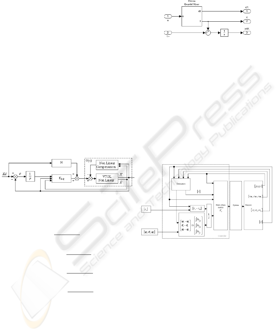
Thus we choose the architecture presented in Figure
2. As the nonlinearity of the VTOL is compensated
by the nonlinear feedback, G(s) appears to be linear
(theoretically). It justifies the use of a linear
quadratic command applied on G(s).
Figure 2: Final control design
The terms coming from backstepping synthesis and
used for nonlinear compensation are as follows:
This nonlinear feedback compensates the projection
of gravity and the gyroscopic effects. For example,
when the quadrotor is tilting, the effect on weight is
directly compensated.
In order to stabilize and to obtain good time-domain
performances, we have chosen to apply an
augmented Linear Quadratic control method as
presented in Figure 3 on the linearized model from
the nonlinear one (3.1).
Figure 3: Synthesis LQ model
Four control inputs u
i
for each electric motor and
twelve states are used.
The eight initial states (3.3) of the quadrotor has
been augmented by four integrators states (3.4)
corresponding to the integrator of the height, yaw
angle, pitch angle and roll angle errors in order to
obtain null steady-state errors in response to step
inputs.
Figure 4: LQ control design
Gyrometers and ultrasonic sound sensor giving
respectively the states
(
)
,,,pqrz and
()
,,pqr
∫∫∫
by
integration, the states
(
)
z
and (3.4) are estimated
need to Kalman filters, with accelerometers and
heading measurements. The Euler angles have been
chosen to control the QuadriXflyer attitude; the last
four states are obtained by integration of the
formulas (3.5) results.
This architecture is displayed in Figure 4. Moreover,
to avoid oscillations on the control inputs coming
from measurement perturbations, a low-pass
frequency filter with a cut-off pulsation of 20 Hz has
been added.
()
()
()
1
cos .
.
2
.
3
.
4
mg
W
cos
II
YZ
Wqr
d
II
Z
X
Wpr
d
I
I
X
Y
Wpq
d
θϕ
⎧
=
⎪
⎪
⎪
−
⎪
=−
⎪
⎨
−
⎪
=−
⎪
⎪
−
⎪
=−
⎪
⎩
(
)
()
()
,,,,, , , 3.3
,,, 3.4
pqr
z pqrz p q r
z
⎧
⎪
⎪
⎨
⎛⎞
⎪
∆∆ ∆ ∆
⎜⎟
⎪
⎝⎠
⎩
∫∫∫
∫∫∫
∫∫ ∫ ∫
MODELLING AND LQ-BACKSTEPPING CONTROL FOR A QUADROTOR
137
The LQ controller tuning was carried out in order to
trade-off performance against consumption via
Q
x
and
R
matrix of a quadratic criterion (3.6).
The
R
matrix is chosen as the identity matrix and the
four diagonal terms of
Q
x
are tuned to master
independently the four dynamics (height, yaw, pitch
and roll) of the quadrotor, we have regulated these
dynamics independently. Due to slow dynamics in
height and law compared to the pitch and roll
dynamics, these weightings have been augmented
and chose to respect the QuadriXflyer requirements
(stability, temporal performances like overshoot,
time delay, oscillations).
Finally, we observe that the synthesized controller
(Table 1) will act in a natural way on the system.
Table 1: Synthesized controller
We add a static matrix of feedforward controller H
that allows pre-compensating slow poles of actuators
by introducing zeros in the closed loop.
Physical considerations suggest the following
structure for H:
Each column corresponds to a dynamic (height,
roll…) and each row corresponds to an actuator. If
the actuators were perfect, each column would have
parameters with same absolute values. However it is
possible to consider differences between rotors
dynamics by tuning these parameters.
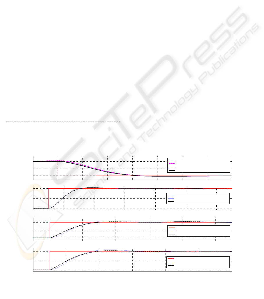
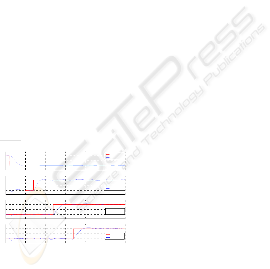
The simulation 1 allows the effect of the
feedforward controller and the terms coming from
backstepping to be comparing.
The nonlinear compensation effect appears at the
simulation beginning to maintain the quadrotor
height. The feedforward controller accelerates the
quadrotor response after a roll or pitch demand.
0
0
0
0
hhh
z
hh h
z
H
hhh
z
hh h
z
ψ
θ
ϕ
ψ
ψ
θ
ϕ
ψ
−
⎡
⎤
⎢
⎥
−− −
⎢
⎥
=
⎢
⎥
−−
⎢
⎥
⎢
⎥
−−
⎢
⎥
⎣
⎦
1
2
3
4
6.1 0 1.1 21.8 4.5 0 0.7 10.2 4.2 0 0.9 23.4
6.1 1.1 0 21.8 4.5 0.7 0 10.2 4.2 0.9 0 23.4
6.1 0 1.1 21.8 4.5 0 0.7 10.2 4.2 0 0.9 23.4
6.1 1.1 0 21.8 4.5 0.7 0 10.2 4.2 0.9 0 23.
z
p
qr
zpqrzpqr
u
u
u
u
∆∆ ∆ ∆
⎛⎞
−− −−
⎜⎟
⎜⎟
−− − −− −
⎜⎟
−− − − −
⎜⎟
⎜⎟
⎝⎠
−−− −−
∫∫∫
∫∫∫ ∫∫ ∫ ∫
4
⎛ ⎞
⎜ ⎟
⎜ ⎟
⎜ ⎟
⎜ ⎟
⎜ ⎟
⎜ ⎟
⎜ ⎟
⎜ ⎟
⎝ ⎠
()
()
.. ... 3.6
TT
x
JxQxuRudt=+
∫
()
()
()
()
()
() ()
()
()
()
() ()
()
()
sin .
3.5
cos . sin .cos .
sin . cos .cos .
d
dd
dd
dd
zz z
p
q
r
ϕϕ θψψ
ϕθ θ ϕ θψ ψ
ϕθ θ ϕ θψ ψ
∆= −
⎧
⎪
∆= −− −
⎪
⎪
⎨
∆= −+ −
⎪
⎪
⎪
∆=− −+ −
⎩
∫
∫
∫
0 1 2 3 4 5 6 7 8
-10
-5
0
Hei ght (m)
6 8 10 12 14 16 18
0
5
10
Psi (deg)
12 14 16 18 20 22
0
5
10
Theta (deg)
16 18 20 22 24 26 28
0
5
10
Time (sec )
Phi (deg)
Consign
Measurement without NL compens
Measurement without pre controller
Measurement with pre controller
Consign
Measurement without pre controller
Measurement with pre controller
Consign
Measurement without pre controller
Measurement with pre controller
Consign
Measurement without pre controller
Measurement with pre controller
Simulation 1: Comparison between the effect of the precontroller and the terms coming from backstepping
ICINCO 2005 - ROBOTICS AND AUTOMATION
138
4 ROBUSTNESS STUDIES
Since the QuadriXflyer model is nonlinear, gain,
phase and delay margins are not representative. To
ensure stability and the respect the time-domain
performances when the quadrotor is subjected to
exogenous disturbances (wind), internal disturbances
(noises on measurements) or uncertainties (inertia)
on the synthesis model, some robustness studies
have been performed.
These studies take into account:
Bias and variance on the gyrometric
measurements.
Variance on the accelerometer
measurements.
Cap measurement perturbations to simulate
a disturbing element like a magnetic
material near the sensor.
Command perturbations to simulate a wind
gust, an air pocket.
Height measurement perturbations to
simulate the fast passage of a disturbing
element like a tree between the quadrotor
and the ground.
Inertia errors in the model synthesis due to
a false approximation in his theoretical
calculation.
Lack of precision on the parallelism of the
propellers.
Example
: Robustness study with variance on the
accelerometer and gyrometric measurements:
Simulation 2: Robustness study
The QuadriXflyer is stable even if we can observe
(Simulation 2) low oscillations on the pitch, roll and
yaw dynamics.
5 CONCLUSION
In this paper we have proposed a modelling and a
new hybrid LQ-backstepping control method for a
quadrotor. This method combines nonlinear and
linear controls and makes it possible to compensate
in particular the nonlinear effect of gravity while
preserving the performances of an LQ controller.
The introduction of a feedforward controller allows
the compensation of slow poles of the system, in
particular those of the actuators without system
stability deterioration.
ACKNOWLEGMENTS
We would like to thank Arnaud Mainsant and
Rachid El Mafkouk for their participation to this
work. We also thank Roland Bouttes, Daniel
Alazard, Pierre Apkarian and Philippe Mouyon for
their encouragements.
REFERENCES
Bouabdallah, Murrieri, Siegwart, 2004. In Design and
Control of an Indoor Micro Quadrotor. Proc. IEEE,
ICRA. New Orleans, USA.
Altuğ, Ostrowki, Mahony, 2002. In Control of a
Quadrotor Helicopter Using Visual Feedback, Proc.
IEEE, ICRA. Washinton, USA.
Hamel, Mahony, Lozano, Ostrowski, 2002. In Dynamic
modelling and configuration stabilization for an X4-
flyer, IFAC. 15
th
Triennal World Congress, Barcelona,
Spain.
Pounds, Mahony, Gresham, 2004. In Towards
Dynamically-Favourable Quad-Rotor Aerial Robots,
ACRA, Australia.
Bouabdallah, Siegwart, 2005. In Backstepping and sliding
mode techniques applied to an Indoor Micro
Quadrotor. Proc. IEEE, ICRA. Barcelona, Spain.
Fantoni, Antoni, Lozano, Nazenc, 2001. In Control of the
PVTOL aircraft using the forwarding technique and a
Lyapunov approach, European Control Conference,
ECC2001, Porto, Portugal.
Praly, Ortega, Kaliora, 2000. In Stabilization of Nonlinear
Systems via Forwarding mod, Control in the year
2000, LNCIS Vol. 246, eds. A. Isidori, F. Lamnabhi--
Lagarrigue and W. Respondek, Springer--Verlag,
London, England.
0 5 10 15 20 25 30
-10
-5
0
Height
Consign
Measurement
0 5 10 15 20 25 30
0
5
10
Psi (deg)
Consign
Measurement
0 5 10 15 20 25 30
0
5
10
Theta (deg)
Consign
Measurement
0 5 10 15 20 25 30
0
5
10
Time (s ec )
Phi (deg)
Consign
Measurement
MODELLING AND LQ-BACKSTEPPING CONTROL FOR A QUADROTOR
139
