
LOWER LIMB PROSTHESIS: FINAL PROTOTYPE RELEASE
AND CONTROL SETTING METHODOLOGIES
Vicentini Federico, Canina Marita, Rovetta Alberto
Robotics Laboratory, Mechanical Department - Politecnico di Milano – Itlay
Via Bonardi 9, 20133 Milano - Italy
Keywords: Lower limb prosthesis, biorobotics, human-machine interface, control, step analysis.
Abstract: The current research activity on prostheses project at the Robotics Laboratory (Mechanics Department,
Politecnico di Milano) is carried on in cooperation with Centro Protesi INAIL and STMicroelectronics. The
team is both innovative and interesting, owing to the fact that it not only involves a range of specialists but
also gives rise to interdisciplinary aspects. They are absolutely essential in project dealing with such
complex issues. This Mechanic-Leg project, called Hermes, is an original solution in the field of prosthesis.
Main aim of this research is the prototyping of a new kind of mechanical lower limb with an electronic
control. The device, resorting to innovatory mechanical and electronic solutions, allows the controller to
modify the type of step, passing from a slow to a fast walk, in an easy and intuitive way, taking care of
patient’s requirements. The Hermes M-Leg cost is comparable to the actual commercial non electronic
controlled artificial knees. The distinguishing features of Hermes M-Leg project are an higher awareness in
innovative aspects related to medical/biological/engineering research. Then, a pervasive use of cutting-edge
technology (electronics, IT, material-related technologies, etc.). The controller architecture is built upon a
low memory processing features. The hard analysis and test activity help to model the algorithm for step
control. The adaptive behaviour is mostly due to an effective experience in testing and software tuning in
cooperation with patients and clinical staff.
1 INTRODUCTION
A prosthetic system, totally replacing a lost human
body part (thereby ensuring the functionality of a
specific physiological system), acts as a true spare
part which the person is able to interact with. The
prosthesis designer takes into particular account the
man-device interface. This is done to satisfy the
patient driven requirements and to project a suitable
prosthesis. According to this statement, a innovative
design concept emerges in evaluating the prosthesis
system.
The prostheses technological evolution has begun in
sixties. The availability of advanced technologies
coming from the automotive and aerospace industry,
allowed to develop more comfortable, resistant and
light materials. The prosthesis weight limitation is
indispensable to reduce the user tiredness and to
allow a longer use during the day. In the 80s, new
materials were introduced provided of similar
mechanical resistance but lower density compared to
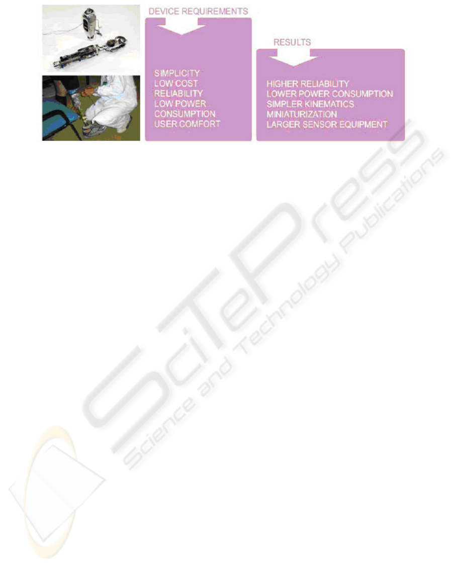
previous ones. The miniaturization of components is
actually fundamental in the design system; it allows
to reduce the prosthesis overall weight. So that many
global requirements have arisen from technology
development to user comfort. First, an electronic
controlled prosthesis must give stability to the
patient, support his weight and make his/her
movements easy. Therefore, it is very important to
minimize energy supplied by the patient and to fit a
natural limb behaviour. Finally, the device should be
adaptive and self learning.
In this paper it will described a methodology in
device optimization from several points of view. The
final release prototype developed mixes up design,
mechanics and software issues due to long
experience in prosthesis field. An accurate analysis
is carried on about all design process, and it will be
presented as well as a short description of produced
device.
232
Federico V., Marita C. and Alberto R. (2005).
LOWER LIMB PROSTHESIS: FINAL PROTOTYPE RELEASE AND CONTROL SETTING METHODOLOGIES.
In Proceedings of the Second International Conference on Informatics in Control, Automation and Robotics - Robotics and Automation, pages 232-241
DOI: 10.5220/0001185502320241
Copyright
c
SciTePress
2 DESIGN METHOD OF THE
M-LEG SYSTEM
Accurate design of a lower limb prostheses requires
analysis aimed at defining shapes, materials and way
of utilization. Analysis issues are related to general
requirements coming from both experience and
commitment outlines. One of the goals of the
research work is to design a prosthesis equipped
with some trick for storing energy. It would also
enable an amputee to perform almost the same type
of (even complex) movements as those performed
with a natural limb. Another objective of this project
is the development of the mechanical structure
strongly oriented to criteria of maximum reliability.
So, through the design process, two criteria were
identified: a functional and a structural criterion.
When the design was in progress, however, a hard
reduction in sizes was crucial. It aimed to reduce
overall prosthesis weight and get the best
compactness compared to requirements and
constraints. The prosthesis must satisfy two different
requirements relative to the de-ambulation. First is
stability. This requiring the assessment of robust
geometries in relation to steady loads. Second
requirement is related to specific leg and foot
trajectory, so it requires a variable geometry.
Naturally in the M-Leg prosthesis both requirements
are satisfied within the same system. A prosthetic
device for a thigh amputee must allow general de-
ambulation conditions. Each movement situation,
i.e. walking, climbing stairs, sitting, running, shows
different kinematical and dynamic characteristics.
The prosthetic mechanism must be designed for
flexible efficiency in all of them. In the prostheses
design over the last few years two phenomena have
come to light:
• The exponential development of electronics
applied to prostheses;
• The increase of models differing widely from those
currently available - from those equipped with only
a spring to those with hydraulic circuits-.
These two elements are closely connected; in fact,
both are linked to the fast progress in electronics, to
the consequent cost reduction, to increased
processing and storage performance of chips and,
most of all, to the increasing convergence of
mechanics and electronics. Listed requirements are
all related to behavioural or mechatronic issues.
They must be managed in an innovative way,
encoding a methodology starting, for instance, from
the design approach.
The knowledge in creation processes, analysis
methods and design procedures allows a team to use
not only the most suitable technology but also a
methodological approach for complex problems
solving. This process involves different stages each
of which needs subsequently to be validated.
Researchers and designers fundamental task lies in
the ideas “materialization” through effective
methods, pursuing fast and competitive product for
market. Even in research field, effective tool must be
developed in order to gain large yield in innovative
applications. The decision to begin a new system in
the high tech devices sector involves the undertaking
of a process that is generally not only long and
expensive in procedural terms but also in cognitive
terms. The first step is the design phase. It includes
an initial project plan involving:
• analysis of the available technologies as well as
those required;
• selection of technological tools to be used;
• choice of materials and validation protocol;
• realization of prototypes;
• exploration of available clinical data, either inside
the team skills or likely to be found in literature on
similar products;
• assessment and reformulation of specifications;
Figure 1: general design requirements
LOWER LIMB PROSTHESIS: FINAL PROTOTYPE RELEASE AND CONTROL SETTING METHODOLOGIES
233
As a result, a structure of relationships among
overall requirements leads towards project
statements. This procedure may be codified and
shared among the project team. Such procedure has
been applied in last activity and final prototype
production. In the next section it will be described
the analysis methodologies transfer to project details
and components.
3 ACTUAL RELEASE OF
ARTIFICIAL LIMB
PROSTHESIS. FROM DESIGN
METHOD TO COMPONENT
DESIGN
Long trained prototypes and maturity of skills in
limb prosthesis development have drawn into final
release of the artificial knee. This is due to a
complete review of previous releases and to the
fulfilling of special requirements in every detail.
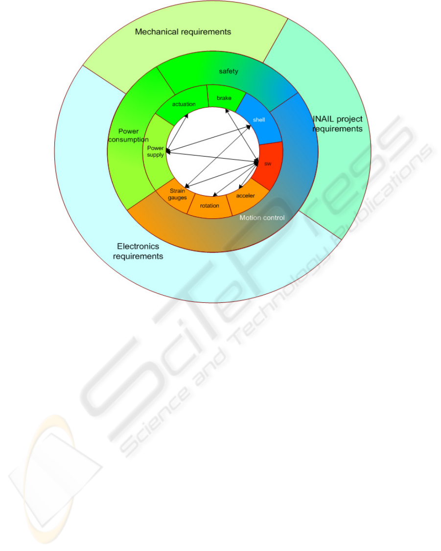
Conceptual scheme in figure 2 depicts the
relationships between project requirements,
functional features of the device and related
hardware components. The scheme helps the team to
manage the design effort. The design action is
particularly devoted to clinical and safety aspects.
Moreover, from a technical point of view, the
motion control involves the largest part of hardware
components. Many efforts are given in
accomplishing an artificial device behaviour as
natural as possible. Both these high level
requirements are interconnected in the software
features for control. For this reason, the control
represents the final largest activity. Many tests and
control concepts are developed on the basis of
measurements and sensors acquisition. In section 4 it
will be described the general architecture and the
tests carried for that. Finally, another large efforts in
developing the final release is due to sensor
equipment. It has been enriched from the last release
and many components have been re-engineered.
Both safety and motion regulation are due to a brake
system. Figure 3 depicts the global requirements,
most of which are related to a robust and reliable
braking system. The requirements analysis in the
Figure 2: requirements and components
ICINCO 2005 - ROBOTICS AND AUTOMATION
234
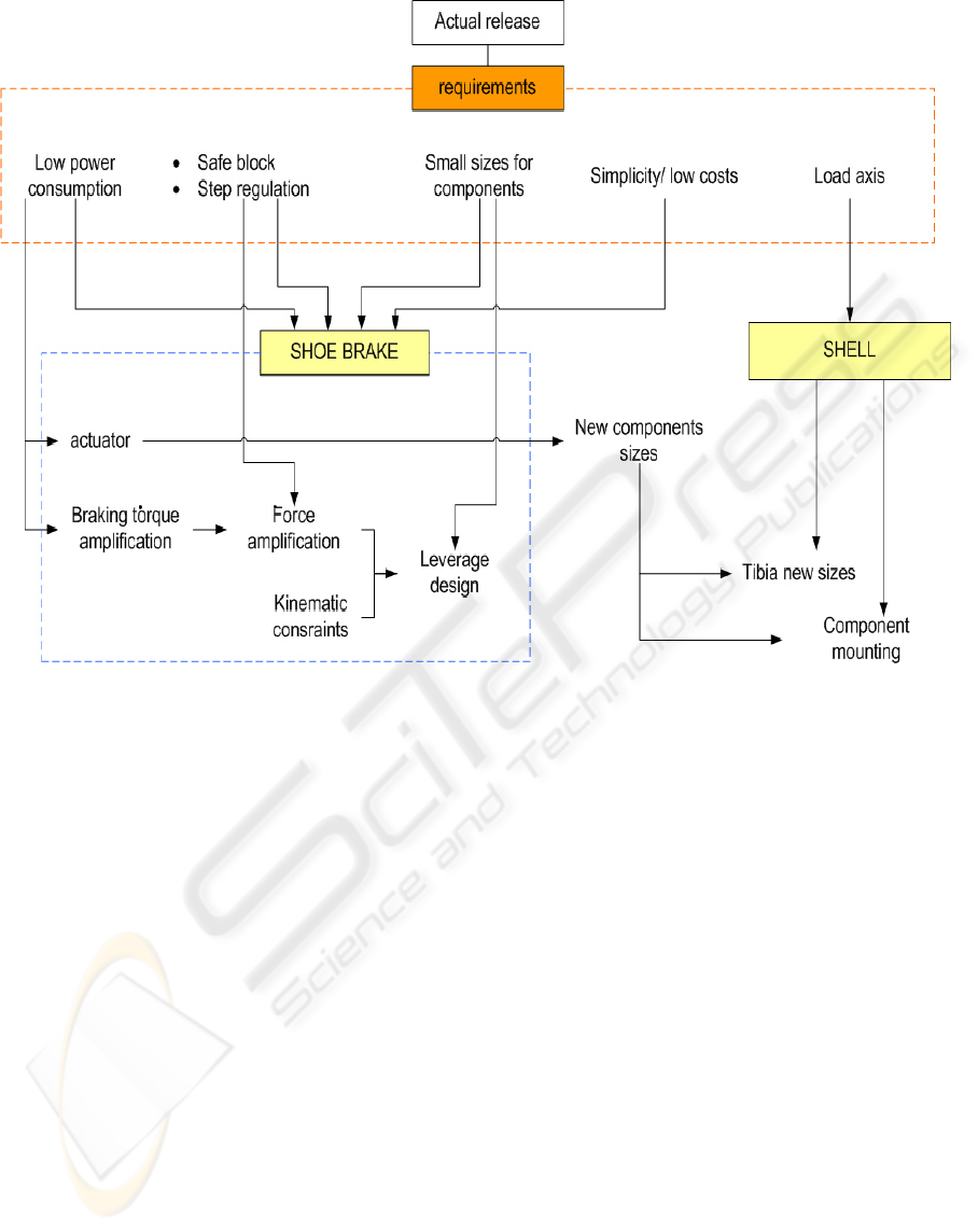
scheme makes the general requirements of figure 2
deeper. It shows the features of core components to
develop or re-design. Design choices in the whole
mechanical equipment are taken upon this analysis.
The produced prototype works on combined active
and resistive principles. The device is not designed
to autonomously provide energy for walking. For
this reason a constant force spring is used to
accumulate energy, during hip backward flexion.
This energy, coming from user stump, is given back
to motion of the artificial limb by the spring itself.
The step regulation, during both the walking and
other conditions, is due to a shoe brake. It is
mounted inside the artificial knee and guarantee
reactive force and safety. It’s clear why the brake
system represents the largest design effort from a
mechanical point of view. In analysis scheme, the
choices about the braking technology, the auxiliary
mechanisms and the mounting structure are taken on
the basis of a well planned design process.
The mechanical system is designed to be functional
to control action. The control itself, however, is
submitted to the same general requirements of figure
1. In particular low power consumption, simplicity
and low costs are the main features to achieve in
software development. The electronic control must
be reliable and effective using a limited amount of
memory and processing performances. The design
challenge is related to optimization of control action
by hardware available. For this reason the device is
equipped with several sensors which supply
information to recognize artificial limb dynamic.
Finally, the design aspects are very important to
compactness of the device. It must be stand alone,
reliable and safe. The design contribution proves
itself in hardware components definition, the
structure and shape of the device in order to let the
user feel comfortable. The user must be supported
and facilitate during all motion situations, allowing
flexibility of movements and stability.
As a result a very compact device is developed and
tested. In order to fulfil many requirements, the
electro-mechanical brake is used as regulation
system. Moreover, it’s mounted in a way that let the
housing of rotating mechanical parts. Functional
kinematical components are all mounted around the
Figure 3: brake system requirements analysis
LOWER LIMB PROSTHESIS: FINAL PROTOTYPE RELEASE AND CONTROL SETTING METHODOLOGIES
235
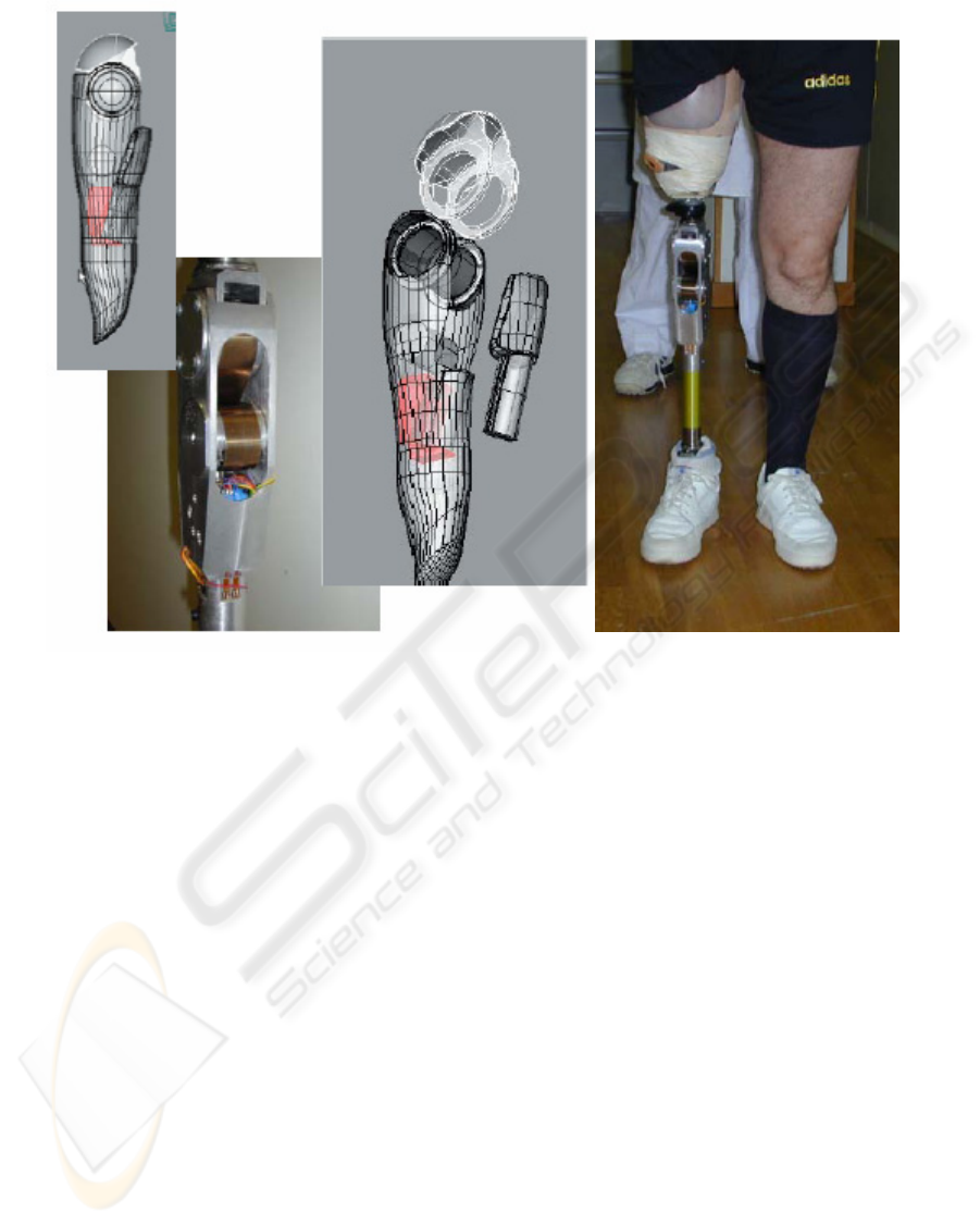
knee knuckle, even the elastic part in knee joint. M-
Leg is a semi-passive prosthesis because of partial
potential energy accumulation. The particular shape
of the spring makes it very easy to control. The
overall compactness is evident from the electronic
equipment above anything else. The micro-
controller by STMicroelectronics allows data
acquisition, signal conditioning and output
generation; it is a very miniaturized equipment and
provides the correct execution control algorithm. It
must be pointed out that, under many aspects, the
innovatory criteria applied along all the phases of
the development are original in solutions, ever used
before in none of the existing prosthesis.
4 CONTROL STATEMENTS
METHODOLOGY
The control target lies in device adaptation to
different dynamic conditions of user motion. The
device must follow the behaviour of a natural leg
and give a good mechanical response to user needs
in equilibrium and mobility. It must do this in real
time mode. Information coming from sensors input
is very important to outline the current situation. The
update of signal reading and output elaboration
allow the artificial knee to supply the right action.
The input channels are knee joint rotation, stress on
lower leg structure and upper segment acceleration.
The signals are provided by common strain gauges
for compression and bending, and micromachined
sensors for inertial parameters. The knee rotational
speed is calculated by the rotation angle derivative.
A calibration session has been done before using
such signal. The kinematics of knee joint is single-
centre, i.e. it has only one centre of rotation, and an
external reference is used to check the linearity of
sensor response. This procedure is required because
the potentiometer is not mounted directly on rotation
axes, but its connected to displaced integral shaft.
The software design comes after the acquisition
session of the whole sensor equipment. This is
necessary to find out the recursive patterns in step
evolution and, in parallel, in signal records. The
pattern recognition phase is especially done for
walking conditions. This is the case of major content
in regulation statements. The walking shows
periodicity of profile during the step cycle. But it’s
marked by a large variability. This is added to noise
and variability of input signals. As a result it
Figure 4: final release. Design, compactness and test.
ICINCO 2005 - ROBOTICS AND AUTOMATION
236

happens to be very useful to have several sensor
available for step condition clustering. It’s only by
all signals comparison that the walking behaviour
can be recognized. The preliminary phase for control
algorithm design is to recognize periodical pattern at
a reference conditions and to use the brake action
without any regulation. (The fundamental feature of
an electronic controlled device is the real time
adaptation to different conditions).
The walking pattern recognition is the result of an
accurate analysis on the acquisition of final release
device. The analysis is based upon the long trained
experience in step recognition during the many years
limb prosthesis development. That experience
proves to be very useful now that the input signals
for control are related to final device and very
reliable.
In this section the preliminary study of control logic
is discussed. First the signal acquisition from sensor
is described. The records are used to define the
signal recurrent patterns. Pattern are the basis on
which a real time recognition and regulation
algorithm is able to work. Then a number of states
are defined in order to cluster the recorded patterns.
This phase is very important because it is the
modelling approach for software architecture. The
states definition allows to set the transitions between
states and the pattern related to transitions. Then the
control unit is turned on, but only for simple
constant impulse. This working mode is used during
explorative tests in order to map the relationship
between step velocity, sensors information and
braking effect.
The motion analysis starts from walking. The
framework for signal interpretation is the natural
walking. the topics is well known and several studies
have been done in Biomechanics in last decades.
Many techniques let experts to measure biometric
parameters, such as rotations, angles, segment
position and so on. Literature data are very
important in finding out related pattern in records
from an artificial device. Such data set the walking
cycle or step as the complete motion of both lower
limbs between two following resting upon ground by
the same foot. The step can be split into two main
phases: the stance phase, when a foot is touching the
ground and the body weight is diversely leaning on
that foot, and the swing phase, when the same foot is
lifted from the ground and flies straightforward. The
stance starts from the heel rest. Then the foot sole
rolls as long as the toe leaves the ground. In that
moment the swing starts till the next heel ground
touch.
The whole cycle is made up of 60% of stance and
40% of swing. The symmetry and periodicity of
walking may induce to give the same duration to
both the phases, but for a small amount of cycle both
the feet are resting on the ground. This is counted in
stance. There are two short interval of simultaneous
foot resting within the cycle, each counting the 10%.
Both stance and swing phases can be divided into
sub-phases. This is due to better understanding the
step dynamic and recognizing it in signals records.
The stance phase is formed by five sequences.
1. initial contact: this is very critical in the
step dynamic. The safety of standing on the
artificial limb depends on this moment for
the largest part. The firmness of the
artificial limb must be comparable to
natural one, both for safety and for self
confidence in motion.
2. first double touch (10% of walking cycle):
the body weight is pushed forward lifting
the rear foot heel and lowering the front
foot toe. In this phase the weight is passing
from a leg to the other and it can be easily
detected by the stress on the device
structure.
3. half touch (20%): from the lifting of the
rear foot toe to the lifting of the front foot
heel. During this phase the rear foot passes
the front one. The weight rests on a single
limb.
4. final touch (20%): starts from the resting
foot heel lifting and goes up to the finish of
the other limb swing phase. This is a very
complex and slight movement to detect.
The touching limb shows a flexion and a
waving pattern affected by large variability.
5. second double touch (10%): inverted
compared to the first.
The swing phase is formed by three sequences:
1. swing start (10%): starts from the lifting of
foot toe. The limb gets a backward
acceleration.
2. half swing (15%): the knee flexion
reaches the maximum extension. The sub-
phase ends at the touching heel lifting. It’s
hard to recognize because of the large
variability of simultaneous values of data
related to maximum extension and heel
lifting.
3. end of swing (15%): starts from the
touching heel lifting till the flying heel
touching. The limb decelerates in order to
prepare the following ground touch.
LOWER LIMB PROSTHESIS: FINAL PROTOTYPE RELEASE AND CONTROL SETTING METHODOLOGIES
237
The sensors signal records are analyzed in
comparison with the natural walking cycle
definition. This is useful for modelling the step
behaviour and building the software architecture. In
real time control is not so important to recognize and
define the whole set of sub-phases.
But there are some critical transitions that must be
detected and complied. In particular, it’s necessary
to react to the swing end before the ground contact,
the flexion extension of flying limb and the whole
weight resting upon only one limb for stability. The
signal used to detect the limb behaviour are the
rotation angle, its derivative, a mixed signal coming
from an arrangement of compression and bending
signals. These signals are given by a double
Wheatstone bridge.
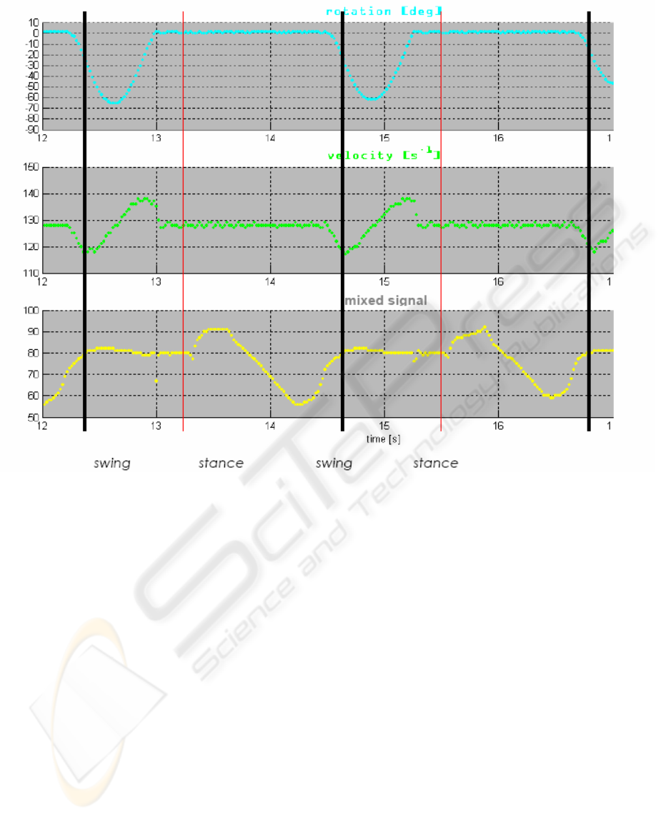
First, such signal are acquired in a test session with
the brake system turned off. The black lines in figure
5 mark the limits of each walking cycle. The red
ones mark the stance and swing phases. The rotation
angle is reported in indirect degrees size. This is due
to the potentiometer return shaft. The relationship
between the knee rotation and the potentiometer
shaft angle has an amplifying factor due to the
different diameters of return mechanism. The
calibration set up guarantee the linear ratio between
knee rotation and potentiometer angle. The mixed
signal size is reported in percentage of weight. The
signal gets the contribution of two types of stress
signal, so the size is not directly related to an
absolute value. The signal used for first analysis are
collected from a standard step succession. The user
is invited to walk as naturally as usual trying to keep
the speed constant. The resulting signals are
averaged among several walking acquisition on the
basis of a predetermined reference point. The output
pattern are very regular and predictable of standard
pattern.
The rotation signal shows the typical pattern, no
hyperextension is supposed to be detected and the
knee flexion happens to be short compared to step
cycle. This is due to the reduction of swing
percentage in prosthesis users. The flying phase of
the artificial limb is faster than the natural one.
One of the objective in device control is to allow the
user walk as much naturally as possible. This means
to arrange the symmetry of walking cycle between
both the limbs. The zero axes crossing in velocity,
Figure 5: acquired signals from sensors equipment
ICINCO 2005 - ROBOTICS AND AUTOMATION
238
related to changing versus of rotation belongs to a
narrow distribution, and the average value of
maximum knee angle recorded is 45°.It’s smaller
than natural value because of the shorter duration of
knee flexion. The lower leg has not enough time to
accelerate and reach larger values. The region of
rotation related to maximum extension is one of the
most interesting in regulation of rotation range. The
reason lies in complete absence of direct control by
the user. The user has non chance to control the
artificial limb backward flexion. This is over the
impulsive energy give to the hip at the start of swing
phase.
The mixed signal is very useful to evaluate the
swing-stance transition and the stance sub-phases.
The mean non-scaled value is related to absence of
weight. It corresponds to swing phase when the
rotation is active and for a while after the complete
knee extension just before touching the ground.
After the heel touches the ground an increase in
signal due to compression stress is gathered. The
peak is short and not marked because of the step
velocity. The body weight, in fact, is thrown
straightforward passing the vertical axis of the
device. In this way the torque due to bending
changes sign and decreasing the value below the
mean. The absolute value is larger the compression
phase one because of the longer leverage for torque
and the duration of rolling on the foot sole. In the
final release the two contribution are separately
evaluated.
From this first analysis two main output are
available: the states definition and the transition
average values. These issues are fundamental in
setting the architecture model for control software
and in software requirements statements. These
features are related to transitions, so the braking
action coming from control regulation must fulfil the
needs of the user shown through the signal record.
From the detected pattern it can be assumed:
1. a brake action is required between swing
and stance in order to guarantee the safety
and stability in touching the ground. The
brake must be on as long as the weight is
passed across the vertical axis.
2. the velocity at the end of swing phase drops
very quickly. This is due to initial
acceleration in forward rotation due to
spring elastic force and the mechanical
block at the complete extension, 0°. This
provokes a stroke to the device transmitted
to the socket and, finally, to the hip and the
backbone of the user. The return rotation
must be decelerated before the end of its
range.
3. other requirements could be revealed by a
finer analysis of device behaviour with the
brake turned on. An important feed back is
given by the user, pointing some features
he may be consider useful or comfortable.
These requirements come from pattern first analysis
and must be added to general ones dealing with
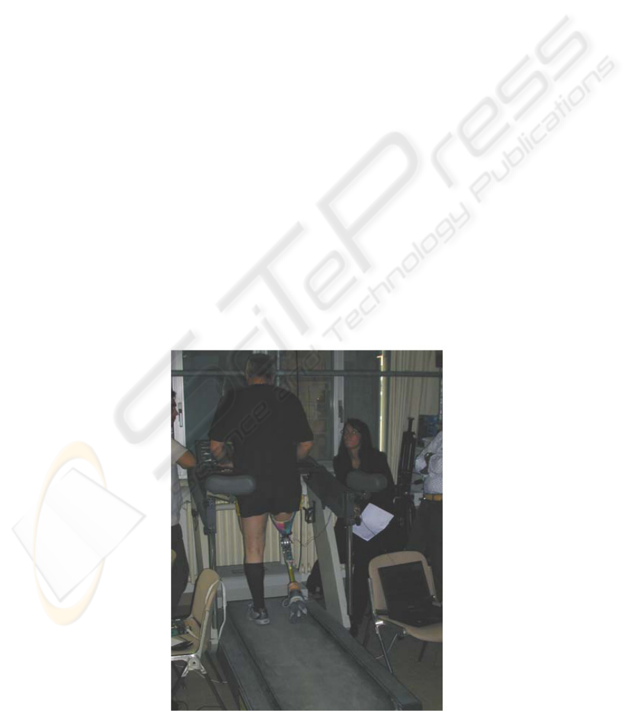
Figure 6: acquisition tests at constant velocity.
LOWER LIMB PROSTHESIS: FINAL PROTOTYPE RELEASE AND CONTROL SETTING METHODOLOGIES
239
emergency management, safe standing upon the
device with the whole or partial body weight,
different motion situations. In particular sitting down
and climbing stairs are test routine run in order to
achieve typical data. The methodology is the same
about different shaped patterns.
The control model is thought to be implemented
through a Finite State Machine (FSM). It’s a
traditional tool to describe formal requirements and
relationships between defined states. It’s not the
control algorithm structure but the ideal framework
of transition management. Such tool is quite
powerful in setting states and transitions, is fit for
limited amount of memory of processor and can be
managed by several people inside the
multidisciplinary team. A first prototype of FSM is
implemented to turn on the brake system in detected
and required points. The initial rules are based only
on pattern analysis. This feature allows the tester to
run some experiments for mapping the dynamic
relationship between braking and step conditions.
Test regulation in control logic is assigned to fixed
velocity/braking position ratio. It’s obviously a
simplification because this ratio changes during the
walking. But for in lab test on leg simulator this is
very useful. It helps to check the right brake
activation due to sensor record and software
regulation. The dynamic step regulation must adapt
the braking action to the velocity and rotation angle.
The dynamics of brake achieve effective resistive
torque as a function of velocity, angle and time
delay in impulse transmission. The larger the
velocity, the larger must be the angle of activation
or, in other words, the advance in getting the speed
reduction. This set of relationships must be fitted
among an empirical data setting and collection. The
experiments take the first step towards the adaptive
control required to electronic controlled prosthesis.
They are carried by a specific tool of calibration and
tuning described below. It’s used to change
regulation parameters both for initial test and for
customization of stand alone final release. For such
reasons a Calibration and customization tool has
been developed.
Initial setting must be run before using the device.
The controller sets internal parameters on the basis
of user features. The main quantity to measure is the
user weight. As usual procedure, the user stands on
the device for a while. The device records a large
amount of values of stress on its structure. The
duration of record may last from six to twenty
seconds. This allows the user to feel free to stand in
natural way. In such way the weight distribution on
both legs, the natural one and the artificial one, has
the chance to vary in a wide range of usual
conditions.
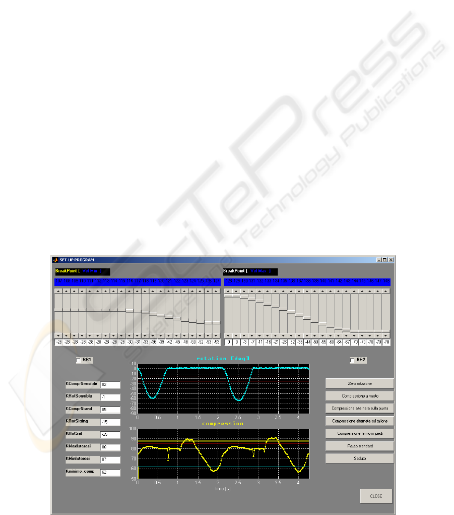
The setting tool has been developed for fine tuning
the recorded parameters. The operator can set
thresholds or constants related to step regulation.
The fine tuning of thresholds is not so usual because
of the initial auto-setting procedure. It’s very useful
to change comparison values inside control software.
This is done to check particular features of device
behaviour. For instance, several tests were run for
Figure 7: tuning, setting and customization tool.
ICINCO 2005 - ROBOTICS AND AUTOMATION
240

understanding the right shape of velocity table curve
during the software development. The user was
forced to experience the same brake activation
response for the whole walk. In that way the step
time and step percentage profile were forced to be
tightly constant. The user was so forced to walk at
fixed velocity. The user was helped in do this by
walking on a tapis roulant so that he could slightly
feel the unnatural step regulation. The amount of
tests was collected varying walking velocity and
brake activation position.
5 CONCLUSIONS
A final prosthesis prototype is the result of a long
design process. Experience and skills are supported
now by coded methodologies and analysis tool. This
process starts from a design approach leading
towards details optimization. It’s important to
underline the methodology contribution to several
re-engineering stages. By means of final release a
large development in direct signal acquisition and
testing became possible. The proposed methodology
for step analysis was done with the constant help and
experience supply of patients and INAIL staff. The
presented methodology is basic for the further FSM
development with self-learning and adaptive
features.
REFERENCES
Dornig A., Le molle, CLUP 1973
Canina M., Vicentini F., Rovetta A., Innovative Design,
Development And Prototyping Of Knee Prosthesis, in
Proceedings of ROBTEP 2004, Automation – Robotics
in theory and practice, 2004
Canina M., Vicentini F., Rovetta A., Innovative Wide
Sensors Integration for Smart Bio-robotic Prosthesis
Control , in Proceedings of RAAD’04, 13th
International Workshop on Robotics , 2004
AAVV, Otto Bock Manuale Protesi, Protesi per arto
inferiore - SCHIELE & SCHON 1988
AAVV, Biomechanics of the musculo-skeletal system (II
edition) – Wiley 1999
Nam P. Suh, The principles of Design – Oxford University
Press 1990
Kapandji, Fisiologia articolare – Soc Editrice DEMI-
Roma 1974
AAVV, Ausili e ortesi in medicina, Vol. 3 – Editrice
Ricerca Medica (Na) 1998
Rovetta A., Canina M., Campa G., Della Santina S.,
Biorobotic design criteria for Innovative Limb
Prosthesis, 9th International Symposium on
Intelligent Robotic Systems, SIRS’2001, Toulouse,
France, 18-20 July 2001
Rovetta A., Canina M., Allara P., Campa G., Della
Santina S., Biorobotic design criteria for Innovative
Limb Prosthesis, Icar 2001, International Conference
on Advanced Robotics, Budapest, 22-26 August 2001
Rovetta, M.Canina, P. Allara, G. Campa, S. Della
Santina, “Biorobotic design criteria for Innovative
Limb Prosthesis”, Mechanika – 2001, Proceedings of
the International Conference, Kaunas, Lituania, April
2001
M. Canina, G. Verni, P. Valentini, Gamba “intelligente”
cambia il passo secondo il terreno, in La Repubblica
Salute anno 7 n. 286, 20 settembre 2001
Hugh Herr, “ Presentation highlights: Prosthetic and
orthotic limbs”, J. Rehabilitation Res.& Dev. Vol. 39
N° 3 (supplement) pp11-12, 2002
D. Zlatnik, “Intelligently controlled above knee
prosthesis,” the 4
th
Int. conf. on motion and vibration
control.
J. H. Kim, J. H. Oh, 2001, “ Development of an above
knee prosthesis using MR damper and leg simulator,”
Proc. Conf. Rob. Aut., Seoul, 1998
J. Slavica, J. Tamara, G. Vladimir, P. Dejan, “Three
machine learning techniques for automatic
determination of rules to control locomotion,” IEEE
Trans. Biomedical Eng., Vol. 46, N°3, pp 300-310,
1999
M. S. Ju, Y. F. Yang and T.C. Hsuch, “Development of
actively controlled electro-hydraulic above-knee
prosthesis,” Proc. Romansy 10/ the 10
th
CISM-
IFToMM symposium, theory and practice of robots
and manipulators, Spring-Verlag Ed., pp 367-372,
1995
M. Canina et all., “Innovative system for the accumulation
of energy of the step in a limb prosthesis,” accepted at
11
th
World Cong. Mech. Mach. Science, August 18-
21, 2003, China.
B. M. Nigg, W. Herzog, 1999, “Biomechanics of the
musculo-skeletal system,” 2
nd
edition, John Wiley and
Sons, England.
D. A. Winter, “ Biomechanics and motor control of
human movement,” Wiley-Interscience Publication,
2
nd
edition, 1990
L. Peeraer et all., “ Development of EMG-based mode and
intent recognition algorithms for a computer-
controlled above-knee prosthesis,” J. Biomed. Eng.
vol. 12, May, pp178-182, 1990
D. Popovic & all., “ Optimal control for the active above
knee prosthesis,” J. biomed. Eng. Vol. 19, pp. 131-
150, 1991
A. Rovetta, X. Wen, “ Biorobotic in a new artificial leg,”
IEEE Int. Symp. on Int. Rob. and Manipulators,
Krakow, 1990
.
LOWER LIMB PROSTHESIS: FINAL PROTOTYPE RELEASE AND CONTROL SETTING METHODOLOGIES
241
