
A META-MODEL FOR THE DIALOG FLOW NOTATION
Matthias Book, Volker Gruhn
Chair of Applied Telematics / e-Business, University of Leipzig
Klostergasse 3, 04109 Leipzig, Germany
Nils Mirbach
adesso AG
Stockholmer Allee 24, 44269 Dortmund, Germany
Keywords:
Web engineering, Dialog Flow Notation, metamodelling.
Abstract:
While the separation of presentation and application logic is widely practiced in web-based applications today,
many do not cleanly separate application and dialog control logic, which leads to inflexible implementations
especially when multiple presentation channels shall be served by the same application logic. We therefore
present a notation for specifying the complete dialog flow of an application separately from the application
logic and show how to construct a formal metamodel for it using the OMG’s Meta-Object Facility (MOF).
This allows the validation of dialog flow models, as well as the generation of machine-readable dialog flow
specifications from graphical models.
1 INTRODUCTION
Complex web-based applications are typically im-
plemented according to the Front Controller pattern
(Singh et al., 2002) today. While it follows the Model-
View-Controller (MVC) paradigm (Krasner, 1988),
many applications do not cleanly separate application,
presentation and control logic when using this ap-
proach. In the popular Struts Web Application Frame-
work (Apache Project, 2005), for example, the con-
troller dispatches incoming requests to actions that
implement or invoke the application logic. After-
wards, they tell the controller which view to display
next, and the controller forwards the request to the
appropriate page. Since the next page to display is
determined by individual actions, the dialog control
logic is distributed over all actions and entwined with
the application logic inside them.
This combination leads to a number of problems:
Firstly, the actions can only make relatively isolated
and local dialog flow decisions, but are unaware of
the “big picture” of the application’s complete dia-
log flow. Secondly, the hard-coded decentralized im-
plementation of the dialog control logic is relatively
inflexible, almost unsuitable for reuse and hard to
maintain or extend. Finally, achieving device inde-
pendence would require additional effort and possi-
bly redundant work: While the dialog flows for vari-
ous client devices may differ depending on their in-
put/output capabilities, the application logic should
be independent of those specifics – however, their
close coupling may prevent the reuse of actions on
multiple presentation channels. Instead, each presen-
tation channel would require its own set of actions to
implement the individual dialog flows for the respec-
tive devices.
To address these challenges, we already presented a
Dialog Control Framework (DCF) (Book and Gruhn,
2003) that decouples not only application and presen-
tation logic, but also dialog control logic and dialog
flow specification from each other. In this approach,
pages (or dialog masks, as we call them) and actions
do not explicitly call other masks and actions, but gen-
erate events that are handled by a central dialog con-
troller. The dialog controller determines the receivers
of events by looking them up in an object-oriented
model of the whole application’s dialog flow, and then
calls the mask or action specified in the model. This
awareness of the “big picture” enables the dialog con-
troller to manage complex dialog structures – in par-
ticular, it allows the nesting of so-called dialog mod-
ules at arbitrary levels. The strict separation of dialog
control logic and application logic also enables conve-
nient reuse of actions in different dialog flows adapted
for various devices.
Having such a framework that can be reused as a
black box to control the dialog flow of any web-based
application, we just need a way of providing it with a
64
Book M., Gruhn V. and Mirbach N. (2005).
A META-MODEL FOR THE DIALOG FLOW NOTATION.
In Proceedings of the First International Conference on Web Information Systems and Technologies, pages 64-71
DOI: 10.5220/0001228000640071
Copyright
c
SciTePress

model of that dialog flow in an efficient manner. For
this purpose, we developed the Dialog Flow Notation
(DFN), a graphical notation that allows the specifi-
cation of complex, modular dialog flows for multiple
presentation channels (Book and Gruhn, 2004). The
DFN was developed with the aim of producing im-
plementable specifications: Its diagrams should not
merely have descriptive, but also constructive power
and be directly translatable into a dialog flow model
that can be used by the framework. This way, we
strive to reduce the development effort and eliminate
the error sources that a manual re-implementation of
the modeled dialog flows would incur.
The Object Modeling Group’s model-driven de-
velopment (MDD) approach seems well-suited to
achieve this goal: Its Meta-Object Facility (MOF)
(Object Management Group, 2002) enables us to cre-
ate a Dialog Flow Metamodel that formally defines
all elements of the DFN and the constraints that need
to be satisfied when building dialog graphs with it.
Using this metamodel, we can equip a graphical mod-
eling tool with semantic awareness about the dialog
flow models that users design, enabling it to check
the models for syntactic and semantic validity and
to generate machine-readable specifications from the
model.
In this paper, after an overview of related work on
the subject of web application modeling (section 2),
we will give a brief introduction into the Dialog Flow
Notation (section 3) and then present its meta model
(section 4) along with a discussion of the issues that
had to be resolved in its design. Using the DFN meta
model, we implemented a plugin for the Eclipse IDE
that allows the graphical modeling of dialog flows.
We conclude with a brief presentation of this tool and
an outlook on further opportunities for using the meta
model in dialog flow specification and dialog control.
2 RELATED WORK
There is a number of ongoing efforts to model web
applications using UML. (Conallen, 1999) defined
a UML profile with stereotypes for components,
classes, methods and association in order to distin-
guish server and client components, server pages etc.
This approach comprises modeling both layout and
implementation aspects, but does not support modu-
larisation except by the use of frames.
Although they extend Conallen’s UML profile,
(Gorshkova and Novikov, 2002) do not add a means
for modularisation. Instead, they focus on modeling
the user interface and separate its functional model
from its presentation characteristics. This way, they
reach a more robust model, which is restricted to
design-time use, however. Both approaches share the
advantage of UML tool support for modeling, but also
the disadvantage of lacking modularisation and con-
structive use of the models in application develop-
ment.
In order to employ the models in the immediate im-
plementation of the application, semantic information
in the form of a meta-model is necessary. (Muller
et al., 2003) examined how the MDA vision can be
applied to web engineering and developed a platform-
independent model for web applications that allows
the generation of whole executable applications. The
complete model of such an application consists of
three parts: the business model, the hypertext model
and the presentation model, which are similar to the
actions, dialog flow and masks of the Dialog Flow
Notation used in our approach.
The approach of Muller et al. goes a step fur-
ther than e.g. (Schattkowsky and Lohmann, 2002),
who developed a UML profile for small and medium-
sized web applications. When developing web appli-
cations with their profile, code fragments for business
logic and presentation logic can be generated from
the model as a starting point for further implemen-
tation by the developers. After this big generation
step, the models are discarded. In contrast, the di-
alog flow model introduced in this paper is updated
together with the application logic and used continu-
ously at run-time.
A big generation step is also characteristic of
the Web Modeling Language (WebML) (Ceri et al.,
2000), which supports the specification of complex
web pages on a conceptual level. WebML distin-
guishes a structural model, a composition model and
the topology of links between pages. In addition, it
allows developers to define layout requirements and
features a personalisation model. However, WebML
is a proprietary language with its own XML represen-
tation and code generation tools, and therefore does
not belong to the MDA standard.
3 DIALOG FLOW NOTATION
The Dialog Flow Notation (DFN) specifies the se-
quence of UI pages and processing steps in an ap-
plication, and the data exchanged between them. It
models the dialog flow as a transition network called a
dialog graph. The notation refers to the transitions as
events and to the states as dialog elements. These el-
ements are further divided into hypertext pages (sym-
bolized by dog-eared sheets and referred to by the
more generic term masks in the DFN) and business
logic operations (symbolized by circles and called ac-
tions here). Every dialog element can generate and
receive multiple events. Which element will receive
an event depends both on the event and the generating
A META-MODEL FOR THE DIALOG FLOW NOTATION
65
Login
check
name,
passwd
submit
incorrect
has
admin
rights?
correct
check
login
status
not yet
logged
in
no
already logged in
mark
user as
logged
in
done
User Authorization
create new
account
register
yes
is admin
is user
cancel
Figure 1: User Authorization dialog module
element (e.g., an event e may be received by action
a
1
if it was generated by mask M
1
, but be received by
action a
2
if generated by mask M
2
). Events can carry
parameters containing form input submitted through a
mask or data produced by the business logic to facil-
itate communication between elements. They are not
bound to HTTP requests or responses, but can also
link two actions or two masks.
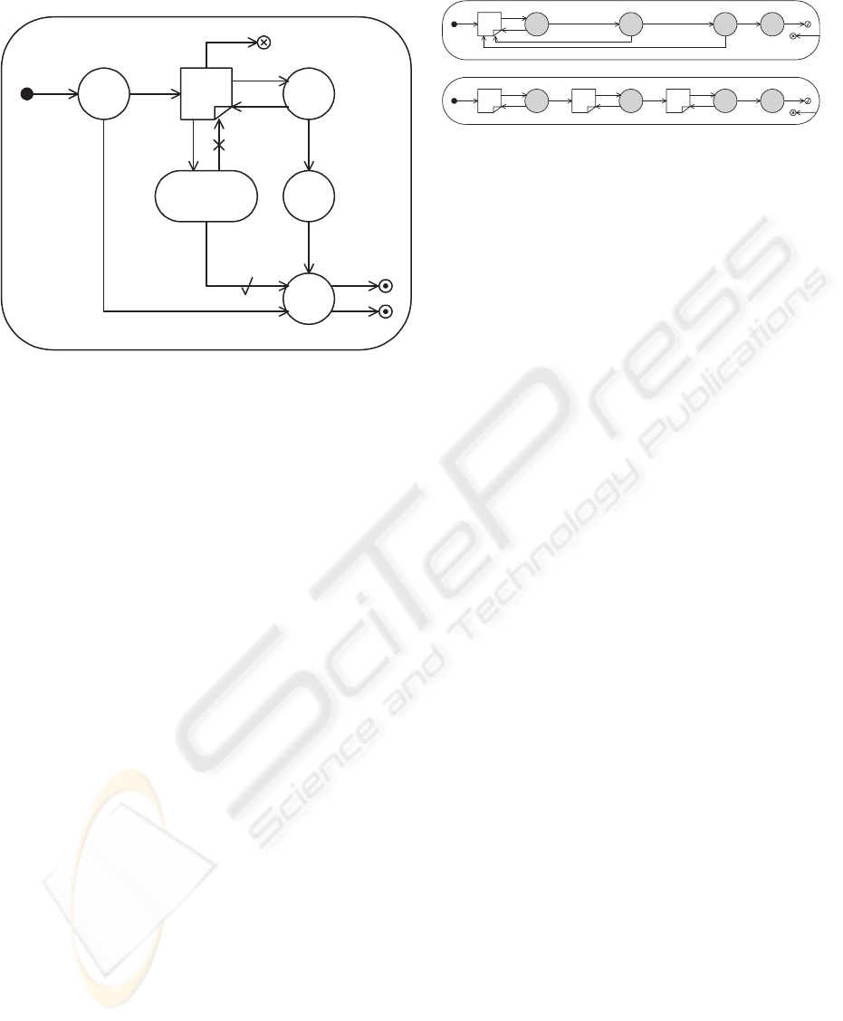
The DFN also provides dialog modules (symbol-
ized by boxes with rounded corners) which encap-
sulate dialog graphs and enable the specification of
nested dialog structures. When a module receives an
event from the exterior dialog graph that it is embed-
ded in, traversal of its interior dialog graph starts with
the initial event. When the interior dialog graph ter-
minates, it generates a terminal event (symbolized
by a circular anchor point in the interior dialog graph
and an arrow in the exterior dialog graph) that is prop-
agated to the super-module and continues the traversal
of the exterior dialog graph (Figure 1). For more com-
plex dialog structures, the DFN offers a number of
additional event and element types (Book and Gruhn,
2004) that we will not discuss here in detail for the
sake of brevity.
To cater to the different interaction patters required
for different client devices, the DFN allows the spec-
ification of dialog flows for different presentation
channels in multiple versions of a module and distin-
guishing them with channel labels (Figure 2). While
the channels employ different dialog masks according
to those devices’ I/O capabilities, they use the same
actions for processing the users’ input, as indicated
by the shading. This enables developers to reuse the
device-independent business logic on multiple chan-
Checkout [WML]
Enter
address
check
address
submit
incorrect
Enter
shipping
data
correct
check
shipping
data
submit
incorrect
Enter
billing
data
correct
check
billing
data
submit
incorrect
correct
place
order
ok
Checkout [HTML]
Enter
address,
shipping,
billing
check
address
submit
incorrect
correct
check
shipping
data
correct
check
billing
data
correct
place
order
ok
incorrect
incorrect
cancel
cancel
Figure 2: Checkout dialog module variants for HTML and
WML presentation channel
nels.
In order to support an efficient transition from spec-
ification to implementation of dialog flows, we devel-
oped the Dialog Flow Metamodel described in the
following section. It formally describes all elements
and constraints of the DFN and enables us to generate
machine-readable specifications in the XML-based
Dialog Flow Specification Language (DFSL) from
graphical dialog flow models. These specifications
can then be parsed by the Dialog Control Framework
(DCF) which serves as an application- and device-
independent interface between presentation and busi-
ness logic.
4 DIALOG FLOW METAMODEL
Without a formal specification of the DFN, the dia-
log flow models could not be used directly for dialog
control since the graphical diagrams would have to be
translated manually into the corresponding DFSL rep-
resentation required by the DCF. This slow and error-
prone process of dealing with two unvalidated and
unsynchronized representations of the same model
would reduce the efficiency of the software devel-
opment process considerably. To enable automatic
validation and transformation of the model represen-
tations, we developed the DFN metamodel. In this
process, we had to resolve three issues that are dis-
cussed in the following sections:
4.1 Formal Specification
The first issue was to find a suitable formalism for
the complete description of DFN models with their
rich syntax and semantics. We chose the Meta-Object
Facility (MOF) standard (Object Management Group,
2002) which defines formal metamodels for platform-
independent metadata and mappings to specific plat-
forms. MOF uses an object modelling framework
for the definition of information models for meta-
data, which essentially is a subset of UML class di-
agrams that provides four main concepts for mod-
elling: Classes model MOF meta-objects, associa-
tions model binary connections between them, data
WEBIST 2005 - INTERNET COMPUTING
66

types model primitive or external data, and packages
unitize the models. The Essential MOF (EMOF) stan-
dard and the Eclipse Modeling Framework (EMF), its
implementation on the Eclipse platform, provide only
a subset of these constructs that is sufficient for simple
and pragmatic metamodelling. While EMOF proved
to be mostly rich enough to describe all constructs of
the DFN, workarounds had to be found for some as-
pects:
• Hierarchical structure: While the DFN supports
and encourages the specification of dialog modules
that are nested into each other at run-time, the mod-
ule specifications themselves are not hierarchical
in nature (in analogy to objects’ methods that may
also call each other at run-time without exhibiting
a hierarchical relationship in their implementation).
Since the metamodel requires its elements to be hi-
erarchically structured in order to be displayed and
serialized properly, however, any references to sub-
modules inside a module were modeled as siblings
of the actual module definitions at the root level.
• Graphical representation: Since the DFN itself
does not contain any information about the graphi-
cal representation and layout of the individual nota-
tion elements in a diagram, this information had to
be supplemented in the metamodel. Each notation
element received additional position and size at-
tributes in order to make this information persistent
and displayable. This could be realized either by
incorporating the layout information directly into
the metamodel or by specifying the necessary in-
formation separately in its own package. To avoid
the unnecessary complexity of cross-package refer-
ences, we chose to specify the layout information
directly in the metamodel.
• Clarity: Convenience and clarity also affected the
design in other ways. The DFN provides vari-
ous types of events which connect various types
of model elements under certain constraints. An
explicit specification of all these n : n relations
would have “polluted” the metamodel with many
associations. To retain clarity, we implemented the
constraints in the model elements themselves and
used inheritance to propagate them among similar
classes of elements: Every model element has an
isTargetFor and an isSourceFor method
that decide if a certain event can be used to con-
nect this element to a certain other element.
• Constraints: More important than the constraints
that were implemented instead of being modeled
for reasons of clarity are those constraints which
are defined in the DFN itself. From widely used
constraints for multiplicity, which can be designed
into the metamodel itself, to complex, context-
sensitive ones, constraints are the heart of valida-
tion in metamodelling. We will discuss their imple-
mentation in more detail in the following section.
4.2 Constraint Implementation
With the DFN metamodel being expressive enough to
cover every correct DFN model, the second challenge
was the formalization of constraints that must be en-
forced on the model to ensure its validity.
Simple constraints are easy to specify within the
metamodel by using MOF constructs like associations
and multiplicities. These kinds of constraints are eas-
ily designed by connecting model elements, but they
can decrease the clarity. To enforce more complex
notation rules, constraints have to be implemented in
the model elements themselves. As an example for a
relatively simple constraint implementation, consider
the following isTargetFor method of the Action
class, specifying that actions can receive terminal,
compound, initial and abort events, but no other event
types:
public boolean isTargetFor(EventElement e) {
if (e instanceof TerminalEvent)
return true;
if (e instanceof CompoundEvent)
return true;
if (e instanceof InitialEvent)
return true;
if (e instanceof AbortEvent)
return true;
return false;
}
The following more complex example implements
a constraint which determines that a Module element
can only generate a terminal event if it is not a so-
called common compound and if its dialog graph con-
tains a suitable Terminal Anchor element. Since these
conditions are context-sensitive (i.e. they depend on
the presence and attributes of other elements that the
designer may use in a concrete model), they cannot be
expressed in terms of metamodel constructs but must
be implemented in a validation routine of the respec-
tive metamodel element. The following excerpt from
the isSourceFor method of the Module class il-
lustrates their implementation:
public boolean isSourceFor(EventElement e) {
if (this.isCommonCompound()) return false;
// search for free RegularTermAnchors
if (e instanceof Event) {
Module toSearch = getModule();
if (!getModule().isRoot())
toSearch = (Module)getModule()
.getRootCompound();
Iterator it = toSearch.getInteriorGraphs()
.iterator();
while (it.hasNext()) {
Iterator anchors = ((InteriorGraph)it.next())
.getEventAnchors().iterator();
while (anchors.hasNext()) {
EventAnchor anchor = (EventAnchor)anchors
.next();
if ((anchor instanceof RegularTermAnchor)
&& ((RegularTermAnchor)anchor)
.getRegularTermEvent() == null)
return true;
}
}
}
A META-MODEL FOR THE DIALOG FLOW NOTATION
67
// ...
return false; // if no condition met
}
The EMF’s Validation Framework uses both the
simple constraint specifications expressed in the
metamodel and the complex constraint implemen-
tations in the isTargetFor and isSourceFor
methods to identify invalid constructs in DFN mod-
els and highlight them in the graphical editor.
4.3 Model Transformation
The third implementation challenge was the trans-
formation of the valid DFN model into DFSL doc-
uments that can be interpreted by the Dialog Control
Framework. Based on the structural information in
the DFN metamodel, each concrete DFN model can
automatically be serialized in the XML Metadata In-
terchange (XMI) 2.0 format by the EMF. The result-
ing file is human-readable, but does not require any
manual processing to make DFN models machine-
readable, which removes a slow and error-prone step
from the application development process.
Since the DCF does not yet support the OMG stan-
dard XMI 2.0, the specification still has to be trans-
lated into the Dialog Flow Specification Language
understood by the framework. For this purpose, we
chose XSLT as the transformation language for sev-
eral reasons: Firstly, there is a direct mapping from
XMI to DFSL since the DFSL only uses a subset of
the semantic data, so the transformation only involves
reducing the XMI document’s contents to the data re-
quired by the framework and building a new XML file
from it using DFSL syntax. Possible synchronization
problems between the two representations of a DFN
model, caused by the batch-like execution of XSLT,
do not occur due to the nature of the development
process, which requires only one transformation be-
fore executing the dialog flow in the framework.
The final transformation is included in the develop-
ment process of web applications through the integra-
tion of an export wizard into the DFN editor.
4.4 Metamodel Elements
After discussing the major issues encountered in the
design of the metamodel, some worthwhile aspects
regarding individual model elements should be men-
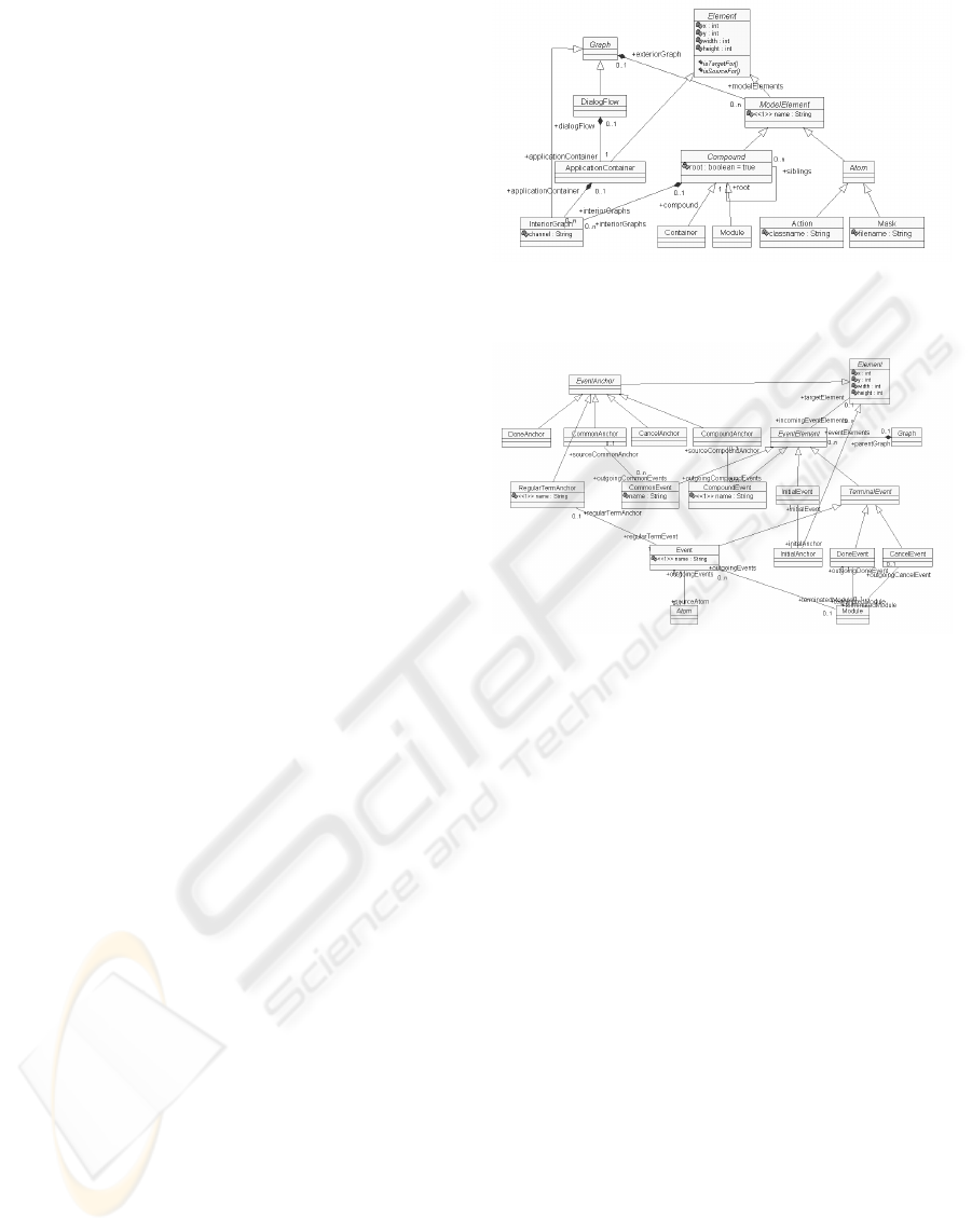
tioned here. Figure 3 shows an excerpt from the com-
plete metamodel that contains classes modeling dia-
log elements.
The Element class plays a central role in the DFN
metamodel. An Element has a position and a size
which are used to display it in a graphical editor, as
well as constraints for linkage with events defined
in the isTargetForand isSourceFormethods.
Figure 3: Metamodel excerpt: Dialog elements
Figure 4: Metamodel excerpt: Dialog events
These characteristics are inherited by every Element
subclass.
Most atomic and compound notation elements
(masks, actions, modules and containers) are modeled
as subclasses of the ModelElement class, where the
Compound class has a self-reference to itself to real-
ize the sibling relationship described in section 4.1.
Also, the so-called application container that contains
the dialog graph the user will initially traverse upon
entering a web-based application is modeled sepa-
rately here to put it on top of the metamodel’s class
hierarchy. Both compounds and the application con-
tainer can contain multiple interior dialog graphs that
in turn contain model elements. By giving differ-
ent channel identifiers to different InteriorGraph in-
stances, we can specify variants of the same dialog
graph for different devices.
This containment hierarchy is a central concept of
the DFN metamodel that is used both by the graph-
ical representation and the serialization mechanism.
Apart from these containment relations, model ele-
ments are also characterized by the type of their in-
coming and outgoing events. These are represented
in the metamodel by the classes shown in Figure 4.
As mentioned before, inheritance was used to ex-
press the relations between elements and events for
WEBIST 2005 - INTERNET COMPUTING
68
the sake of clarity. This is reflected in the metamodel
by specifying the targetElement association only be-
tween the EventElement and Element classes, and let-
ting all other event classes inherit this characteristic
from EventElement. Since this construct potentially
allows any element to receive any event, constraints
for the allowed combinations must be implementated
in the isTargetFor method, as shown in section
4.2.
Another worthwhile aspect to mention is the use
of anchors within the metamodel. While e.g. termi-
nal events use anchors in the interior graph to connect
the dialog flow with the exterior graph, other events
that are called directly by the DCF (such as the initial
event) were originally drawn without an anchor. For a
consistent representation in the metamodel, we added
corresponding anchor elements to the metamodel for
every event that is not generated or received by a reg-
ular element. This way, events in DFN models always
connect two elements.
The graphical editor provides the advantages com-
monly associated with metamodelling: It supports
modelling and enables automatic validation and trans-
formation of domain-specific concepts, with the lat-
ter two steps being essential for increased efficiency
in the software development process compared to a
manual approach. If the DCF supported the DFN
metamodel directly, it could have been integrated with
the DFN editor, and the additional transformation step
into the DFSL could also have been avoided.
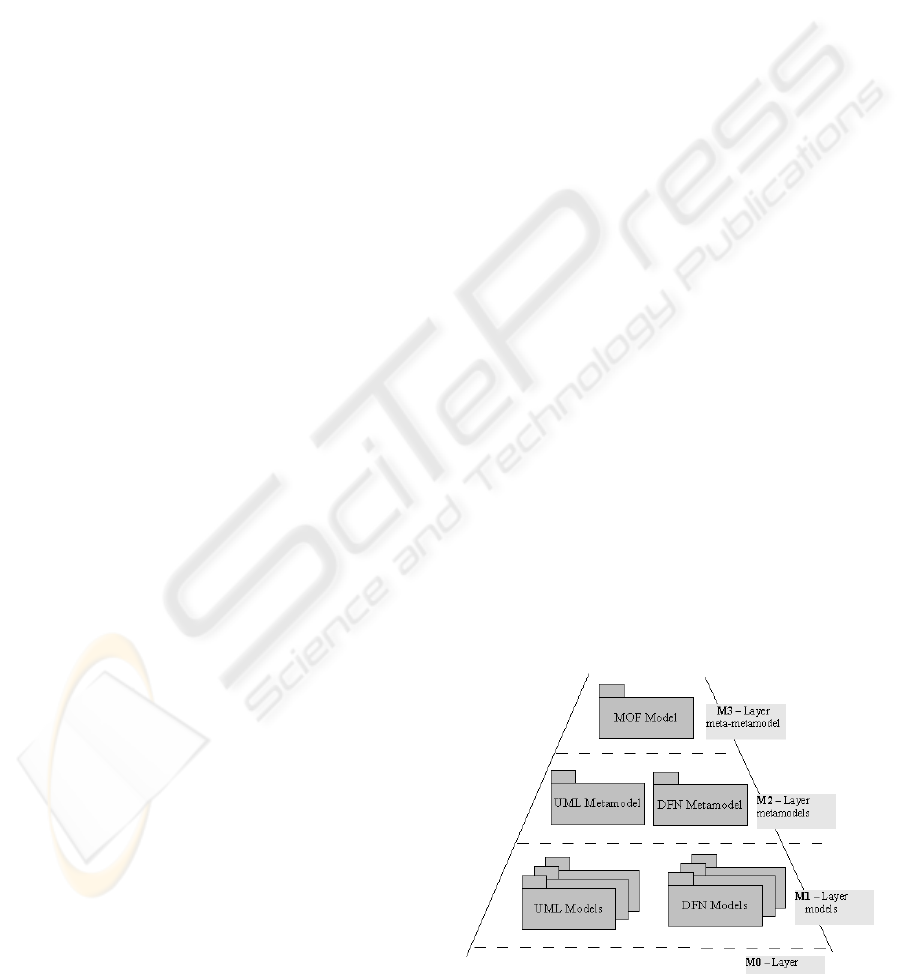
4.5 Metamodel vs. UML Profile
As a meta-metamodel, MOF is capable of describ-
ing new metamodels, as shown in Fig. 5. However,
domain-specific modeling could also be achieved by
extending UML through its profile mechanism. Hav-
ing described the DFN metamodel, one might there-
fore ask why we did not choose to specify the DFN
using an UML profile instead of developing our own
metamodel. To answer this question, we need to con-
sider which way provides the most benefit for mod-
ellers and developers.
(Muller et al., 2003) propose that the development
of a new metamodel is justified if the semantic dis-
tance between UML and the developed language is
too large, and (Desfray, 2000) holds that the definition
of a new metamodel is justified if the described do-
main is well-defined and possesses its own accepted
quantity of main concepts.
Since the DFN was inspired by Statecharts (Harel,
1987) and their concepts resemble each other (apart
from semantic peculiarities of the dialog control do-
main), a solution using UML profiles could have been
chosen in this case. However, we chose to develop
a new metamodel for several reasons: The DFN ap-
plies to the well-defined domain of web application
development, which qualifies it for a metamodel of its
own, according to Desfray. In addition, UML profiles
have some disadvantages compared to new metamod-
els, e.g. insufficient transitivity in the derivation of
properties (Atkinson et al., 2000).
In addition to these more academic reasons, there
were other, more pragmatic ones: The biggest ad-
vantage of UML could be the support of many tools
that are provided by different vendors. Unfortunately,
though, there do not seem to be any robust tools that
provide UML 2.0 profile support, which negates the
biggest advantage of UML profiles. Pending a solu-
tion for this problem in the future, it would be inter-
esting to examine whether the DFN metamodel can be
represented as an UML profile and whether the mod-
elling tools available then can significantly increase
productivity. At this time, however, we found that the
combination of Eclipse’s EMF and Graphical Edit-
ing Framework (GEF) provides comprehensive sup-
port for the implementation of a CASE tool for the
DFN based on a new metamodel.
5 DFN CASE Tool
To demonstrate the feasibility of our approach to di-
alog flow specification and evaluate the advantages
and drawbacks of metamodelling, we implemented a
CASE tool for the DFN. Our plugin for the Eclipse
IDE can manipulate DFN models, validate them and
transform them into DFSL documents.
The choice of Eclipse as the development plat-
form was influenced by (L
¨
uer, 2003), who judged
it as the perfect candidate for the integration of ex-
perimental tools. The DFN CASE tool was devel-
oped as two Eclipse plugins – the DFN metamodel it-
self, implemented using the Eclipse Modeling Frame-
work (EMF), and a graphical editor to manipulate
Figure 5: Relationship of MOF, UML and DFN
A META-MODEL FOR THE DIALOG FLOW NOTATION
69
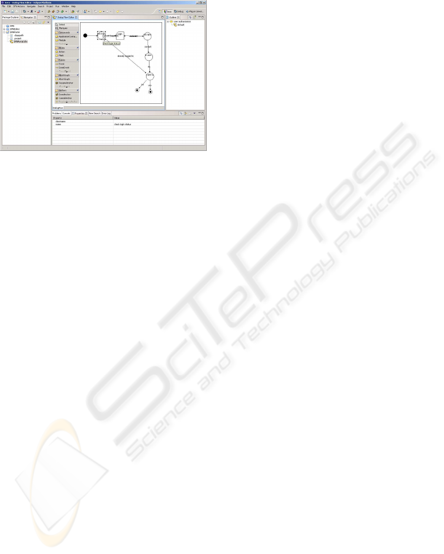
Figure 6: Model of the User Authorization module in the
DFN CASE tool
DFN models, implemented using the Graphical Edit-
ing Framework (GEF). Since the EMF provides a
powerful event mechanism, it was easy to integrate it
into the MVC architecture of the GEF. This way, the
editor can benefit from the metamodel with its default
XMI serialization and validation.
One of the most important features of the DFN
CASE tool is the validation of DFN models and high-
lighting any errors. This way, violations of the DFN
rules can be recognized and eliminated without test-
ing the application. MOF and EMF provide only few
concepts to specify such constraints, which simpli-
fies the development of metamodels, but limits the
choices for validation. A commonly used concept are
upper and lower bounds for attributes and associations
in the metamodel, which can be validated automati-
cally by the validation framework of EMF. The vali-
dation framework also provides basic mechanisms for
the implementation of more complex constraints (e.g.
the Object Constraint Language (OCL) in UML 2.0).
As an example, the screenshot of the DFN CASE
tool in Figure 6 shows the graphical representation
of the User Authorization module introduced in Fig-
ure 1. The following excerpt gives an impression of
the serialized XMI representation of this dialog flow
model:
<dfn:DialogFlow xmi:version="2.0"
xmlns:xmi="http://www.omg.org/XMI"
xmlns:xsi=
"http://www.w3.org/2001/XMLSchema-instance"
xmlns:dfn="http:///dfn.ecore"
xmi:id="dfn_1086773516859">
<modelElements xsi:type="dfn:Module"
xmi:id="dfn_1086773516860" x="73" y="93"
width="80" height="40"
name="user authorization">
<interiorGraphs xmi:id="dfn_1086773516861">
<modelElements xsi:type="dfn:Action"
xmi:id="dfn_1086773516863" x="89" y="47"
width="40" height="40"
incomingEventElements="dfn_1086773516877"
name="check login status"
outgoingEvents=
"dfn_1086773516868 dfn_1086773516872"/>
<!-- ... -->
</interiorGraphs>
</modelElements>
</dfn:DialogFlow>
Given the DFN model in its serialized form, the
XSLT transformation then produces DFSL docu-
ments as input for the DCF. As an example, the fol-
lowing is an excerpt from the User Authorization
module’s DFSL representation:
<?xml version="1.0" encoding="UTF-8"?>
<dfs-flows xmlns:xmi="http://www.omg.org/XMI"
xmlns:xalan="http://xml.apache.org/xalan">
<in-module name="user authorization">
<channel>
<on-init>
<call-action>
check login status
</call-action>
</on-init>
<ex-action name="check login status">
<on-event name="not yet logged in">
<call-mask>Login</call-mask>
</on-event>
<on-event name="already logged in">
<call-action>
has user admin rights
</call-action>
</on-event>
</ex-action>
<!-- ... -->
</channel>
</in-module>
</dfs-flows>
The requirements for the DFN CASE tool were
derived from our Dialog-Driven Software Process
Model (DDPM) that advocates modeling the dia-
log flows coarsely early in the software development
process with a focus on modules and masks, and then
refining it iteratively by adding actions that provide
the application logic that is required to drive the envi-
sioned user interface. Another source of requirements
were our experiences from the development of AR-
GuS, a web-based travel planning system that was still
built without modeling tool support. The DFN CASE
tool can be integrated smoothly into the DDPM with-
out the need for additional processing steps.
6 CONCLUSIONS
In this paper, we presented issues and solutions that
were encountered in the development of a metamodel
for the Dialog Flow Notation (DFN). The aim of this
metamodel is to increase the efficiency of the develop-
ment process for web-based applications by providing
tool support for the design and validation of dialog
flow models and the automatic generation of dialog
flow specification documents.
In order to achieve this goal, several issues had to
be resolved: Firstly, we had to find a formal specifi-
cation mechanism for the DFN that can be used for a
complete description of DFN models with their rich
syntax and semantics. This was accomplished by the
choice of the MOF standard and its implementation in
the EMF. Secondly, constraints imposed by the DFN
rules had to be incorporated into the metamodel in
WEBIST 2005 - INTERNET COMPUTING
70

order to enforce them in the process of model valida-
tion. These constraints were partly modelled as MOF
constructs and partly implemented. Finally, a way for
transforming valid DFN models into DFSL specifica-
tions had to be developed. This was accomplished
by generating the XMI representation of the graphi-
cal model using the EMF and then translating it into
DFSL using XSLT.
To formalize the DFN, we chose to develop a new
metamodel instead of realizing it as a UML pro-
file because of theoretical and practical reasons: The
DFN has its well-defined domain and enough seman-
tic distance from UML to justify an own metamodel,
and UML 2.0 profiles are not supported properly by
today’s tools. We therefore implemented the DFN
CASE tool as an Eclipse plugin to demonstrate the
feasibility of the metamodelling approach for dialog
flow specification. While the first practical experi-
ences with the tool are promising, an experimental
evaluation of its impact on the web application de-
velopment process is still a topic of further research.
The development of the DFN CASE tool will con-
tinue in the future. It would be desirable to support
more aspects of web application development, e.g. by
generating further artefacts such as Java class stubs
for implementing the actions and JavaServer Pages
for implementing the masks. Although the full im-
plementation of these artefacts will remain the devel-
oper’s task, the CASE tool should be able to main-
tain the synchrony between model elements and their
code representation, and allow prototypic dialog flow
execution at design time. This way, the develop-
ment process can be streamlined by avoiding frequent
copying and pasting of class structures and lengthy
testing of simple use cases.
Combining all possibilities offered by the DFN
metamodel, the following scenario can be conceived:
The development of a web application using the DFN
is completely integrated into the Eclipse IDE. While
the dialog flow is designed in the graphical editor, an-
other DFN tool generates stubs for actions and masks
in the same project. This yields a dialog flow that
can be executed directly by a Dialog Control Frame-
work plugin. While the dialog flow is refined and en-
hanced incrementally, the according artefacts are im-
plemented in parallel. This would enable an agile de-
velopment approach, which produces executable code
very early, and is guided by the model of the dialog
flow that is tailored to the users’ requirements.
ACKNOWLEDGMENTS
The Chair of Applied Telematics/e-Business is en-
dowed by Deutsche Telekom AG.
REFERENCES
Apache Project (2005). The Apache Struts web application
framework. http://struts.apache.org.
Atkinson, C., K
¨
uhne, T., and Henderson-Sellers, B. (2000).
To meta or not to meta. Journal of Object-Oriented
Programming, 13(8):32–35.
Book, M. and Gruhn, V. (2003). A dialog control frame-
work for hypertext-based applications. In Lin, H. and
Ehrich, H., editors, Proceedings of the 3rd Interna-
tional Conference on Quality Software (QSIC 2003),
pages 170–177. IEEE Computer Society Press.
Book, M. and Gruhn, V. (2004). Modeling web-based dia-
log flows for automatic dialog control. In 19th IEEE
International Conference on Automated Software En-
gineering (ASE 2004), pages 100–109. IEEE Com-
puter Society Press.
Ceri, S., Fraternali, P., and Bongio, A. (2000). Web Model-
ing Language (WebML): a modeling language for de-
signing Web sites. Computer Networks, 33:137–157.
Conallen, J. (1999). Modeling web application archi-
tectures with UML. Communications of the ACM,
2(10):63–70.
Desfray, P. (2000). UML profiles versus metamodeling
extensions... an ongoing debate. In UML In The
.Com Enterprise: Modeling CORBA, Components,
XML/XMI And Metadata Workshop, Palm Springs.
Gorshkova, E. and Novikov, B. (2002). Exploiting UML
extensibility in the design of web information sys-
tems. In Proceedings of the Fifth International Baltic
Conference on Databases and Information Systems.
Kluwer.
Harel, D. (1987). Statecharts: A visual formalism for com-
plex systems. Science of Computer Programming,
8(3):231–274.
Krasner, G. (1988). A cookbook for using the model-view-
controller user interface paradigm in Smalltalk. Jour-
nal of Object-Oriented Programming, 1(3):26–49.
L
¨
uer, C. (2003). Evaluating the Eclipse platform as a com-
position environment. In 3rd International Workshop
on Adoption-Centric Software Engineering (ACSE
2003), Portland.
Muller, P.-A., Studer, P., and Bezivin, J. (2003). Platform in-
dependent web application modelling. In Proceedings
of the 6th International Conference on UML, Lecture
Notes in Computer Science, volume 2863, pages 220–
233. Springer.
Object Management Group (2002). Meta-object facility
(MOF), v1.4. Technical report.
Schattkowsky, T. and Lohmann, M. (2002). Rapid develop-
ment of modular dynamic web sites using UML. Pro-
ceedings of the 5th International Conference on UML,
Lecture Notes in Computer Science, 2460:336–350.
Singh, I., Stearns, B., and Johnson, M. (2002). Design-
ing Enterprise Applications with the J2EE Platform.
Addison-Wesley, 2nd edition.
A META-MODEL FOR THE DIALOG FLOW NOTATION
71
