
Service Oriented Model Driven Architecture for Dynamic
Workflow Changes
Leo Pudhota, Elizabeth Chang
School of Information Systems, Curtin University of Technology,
PO Box U1987, Perth WA 6845, Australia
Abstract: Colla
borative workflow management systems in logistic companies
require strong information systems and computer support. These IT integration
requirements have expanded considerably with the advent of e-business;
utilizing web services for B2B (Business to Business) and P2P (Partner to
Partner) e-commerce. This paper proposes service oriented model driven
architecture for dynamic workflow changes and strategy for implementation
of these changes by isolation of services and business processes where by
existing workflow systems can easily incorporate and integrate the changes
following a step by step process replacement synchronization in workflow. This
paper describes conceptual framework for prototype implementation resulting
in dynamic collaborative workflow management.
1 Introduction
In this paper we discuss the design of workflow management system for dynamic
business processes of large logistic consortia. Often we see that the business processes
are composed of several parts, a structured operational part and an unstructured
operational part, or they could be composed of semi-structured parts with some given
and some unknown details. Unpredictable situations may occur as a result of changes
in decisions made by the management. The inability to deal with various changes
greatly limits the applicability of workflow systems in real industrial and commercial
operations. This situation raises problems in workflow design and workflow systems
development. We propose workflow implementation through service oriented
architecture and system isolation for making changes to the existing workflow.
2 Dynamism In Collaborative Workflow
The advent of the web is to bind organizations together, for carrying out sales over
great distances and at any time has created new modes for marketing and enabled
partnerships, previously inconceivable within a wide array of businesses, as well as
other human activities [1]. This IT support has expanded with the advent of e-
commerce. However, with this advancement of B2B (Business to Business) and P2P
(Partner to Partner) e-commerce [6], there has been an increasing tendency to set up
Pudhota L. and Chang E. (2005).
Service Oriented Model Driven Architecture for Dynamic Workflow Changes.
In Proceedings of the Joint Workshop on Web Services and Model-Driven Enterprise Information Systems, pages 18-28
DOI: 10.5220/0002545900180028
Copyright
c
SciTePress

consortia that represent several players in a given field. Such consortia consist of
companies or organizations in a given field that get together and produce a single site
or what appears to be single site in order to increase traffic through the site compared
to other competitor’s sites and/or extend beyond their region of operation,
Collaborative workflow management systems of a business sector like logistics
consortium with multi-users and very dynamic environments will have: workflow
specification, workflow execution, workflow evolution, workflow auditing,
transaction management, workflow recovery, workflow interaction (for cooperative
work), and others. The specification of a workflow consists of three items: Process,
Data, Invocation. Changes in a workflow may be an every-day routine in a working
environment. Such changes are of three types: Modification: new workflow has same
objective but different logic and replaces old one. Versioning: as before but new
workflow does not replace old one, but co-exists with it. Extension: new workflow
has different objective and therefore additional logic and replaces old one.
In addition, some environments require dynamic rather than static workflow
evolution, i.e., changing one part of the workflow while another part is running.
3 Web Services For Collaborative Logistic Workflow
A Consortium consists of many departments; generally there are six operational
divisions: Management Department, Warehouse Department, Logistic Department,
Accounts Department, Customer Service Department and Transport Department.
Each department has its own responsibility. However they are connected to each
other. Warehouse Department now already has its own system, so does Accounts
Department. The complexity of works become bigger and bigger when the customer’s
order increase. It is hard to know the progress of the orders and warehouse check. It is
also difficult to schedule the trucks, manpower, etc. Consortium likes to change its
internal work (flow of works among department) and its external work (flow of works
with its customers and other collaborative organizations). Consortium would like to
integrate various departments, and also with other logistic network companies in its
consortium. Consortium also wants its customers to be able to book warehouse
service, logistic service, place orders and view the status of orders, etc on the internet.
This is more like e-commerce way [3]. Here sellers are logistics providers, buyers are
customers and web services brokers are web services integrators, Consortium is
interlinked through internet and services are provided by web services. The basic
premise behind Web Services is that a piece of code is made available to remote
machines, using specific protocols, over the Internet. The Service part of Web
Services relates to the idea of providing access to functionality without having to
download or install the code, and the Web part refers to the means through which the
functionality is accessed [19]. The three component standards of Web Services are the
Simple Object Access Protocol (SOAP), Universal Description, Discovery and
Integration (UDDI), and Web Services Description Language (WSDL) [19].
19

4 Issues Of Dynamism In Collaborative Workflow
Activities and artefacts do not quite constitute a process. We need a way to describe
meaningful sequences of activities that produce some valuable result, and to show
interactions between processes. Changes in collaborative workflow have to be
incorporated into the integrated enterprise system. [8, 9, 10, 11].
In this paper we are concentrating on, 1. Design and Implementation of integrating
solution for adaptation of changes in the new workflow into an already existing
workflow. 2. Synchronization of new workflow to existing workflow. Other issues
like Management of data scattered over multiple origin systems/legacy systems, for
example, a company will have consolidate data in one logical view with a unified
architecture, thereby enabling data-source independence. Because application data
continues to live and change in the origin systems, the new software layer must be
able to retrieve origin data on the fly and also propagate changes back to the origin
systems [17]. Provide support for transactions/interaction across multiple back-end
systems. These issues will help in having a uniform data processing environment for
the whole enterprise, which would lead to changes and improvements in customer
services, control of receivables and increase efficiency in communication, sales,
marketing as well as minimization of warehouse stocks, streamlining inventory and
logistics flows. Provide control to Consortium management to monitor the
collaborative enterprise’s condition, its stock, order and its general financial condition
on a routine basis, This is indispensable to the management processes and enhances
decision-making and changes which need to be taken on the short term and long term
bases for the consortium to compete in the global market.
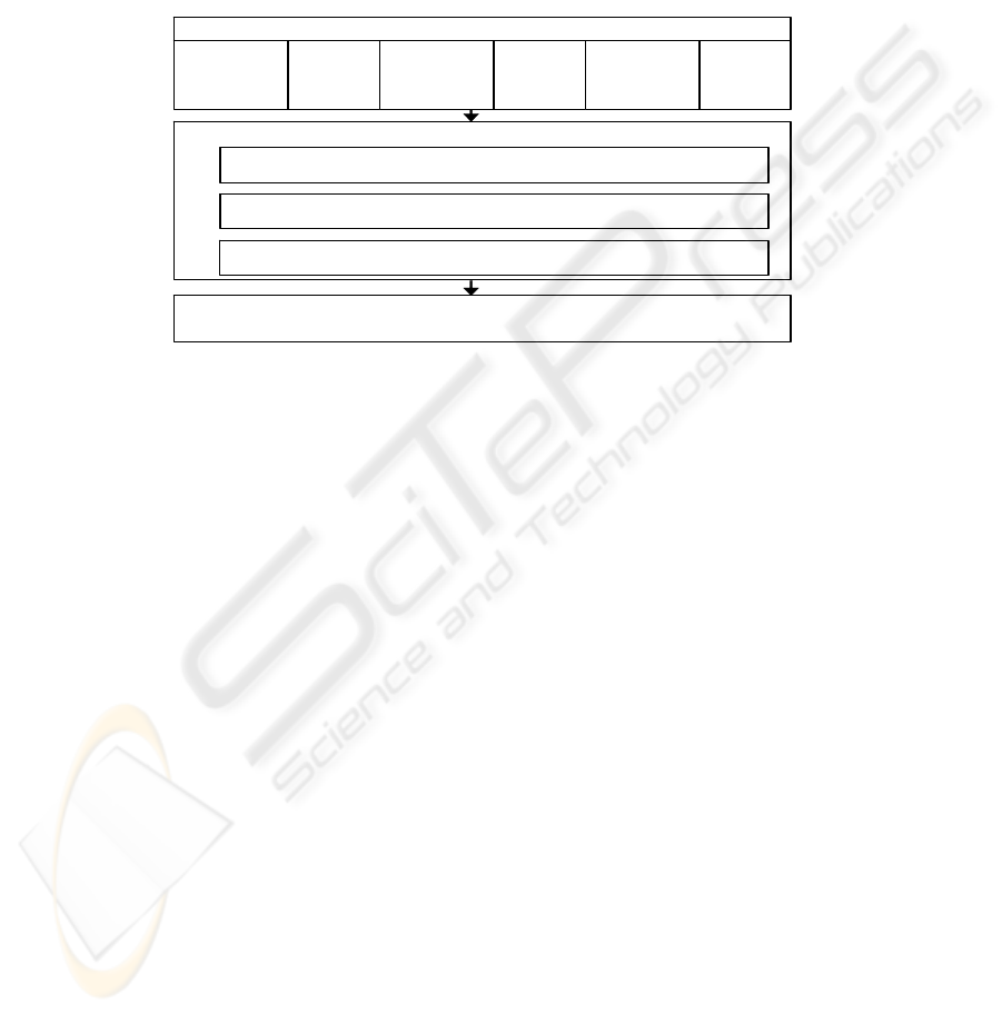
5 Service Oriented Framework To Support Backend
Collaborative Workflow
In this paper we present a service oriented framework for collaborative logistic
companies. The framework is divided in 3 sections 1. Business web services layer. 2.
Services communication layer and 3. Process and transaction layer. In Business web
services layer browsers interact with HTTP servers in their normal way taking
advantage of any technologies that enhance this browser-to-web server link [7].
Enterprise model framework shown in figure 1, balances across one or more
application server processes (also called instances) running on one or more machines.
Once running, Enterprise service framework instances do not go away between user
requests; they maintain themselves, their session’s state for users, and their database
connections. They are efficient, fast, and by definition redundant. It's the job of the
HTTP server adaptor to communicate with a given HTTP server and forward requests
to one or more application "instances" - an instance is a separate copy of a given
application process. Enterprise services framework serving a few users may have only
one instance.
A large application may have tens or hundreds of instances running on one or
more machines. If an application has more than one instance, the Services controller
is essentially acting as load balancing agent. If an instance fails, it only affects that
20
particular instance – all other instances and/or the site's web server is unaffected. The
controller will forward requests over the network as easily as it will forward requests
to applications running on the same box as the HTTP server. In fact, from a load
sharing perspective, it is ideal for the HTTP server and Application servers to reside
on separate boxes, since applications are server based, database access happens
behind the firewall. Browsers need never make direct connections to a database
server. Services access controls database connections so that they are highly secure
(only accessible via actual application API), and conserved (that is, you never have
SERVICES INTERFACE
SERVICES CONTROLER
SERV ICES ACCESS
PROCESS AND TRANSACTION LAYER
SERVICES COM M UNICATION LAYER
1
2
3
4
5
6
BU SINESS W EBSERV ICES LAY ER
Fig. 1. Enterprise model Frame work
more than one connection per service unless this is specifically something the
developers insist regardless of the number of users it supports). Process and
Transaction layer works on underlying java foundation containing fundamental data
structure, implementations and utilities used. we see each department has its own
responsibility; however they are connected to each other. In a collaborative context,
communication may have to be coordinated not only with in the organizations but
also across organizations. Therefore a consortium may require synchronized
coordination of activities of inter and intra organizational departments. This
Conceptual Model provides an architectural separation of business functionality from
technology implementation. This separation allows designers to use business rules
defined in a UML model to drive two distinct steps in implementing such systems.
Step1. Create platform independent models in UML. The first model is a generic
domain model, used to build a common understanding and vocabulary among
warehouse Logistics domain experts. Step2. The domain model is then mapped into a
representing warehouse logistic business. Each of the models includes a detailed set
of UML Class Diagrams, Use Cases and associated Activity Diagrams describing the
system [12].
21

6 Conceptual Model Of Services Communication, Process And
Transaction Layer
This logical architecture of the web services frameworks is a programming building
blocks of the largest granularity. Web services Frameworks is responsible in
providing application’s user interface and state management. Since applications are
server based, database access happens behind the firewall. Browsers need never make
direct connections to a database server. Services access controls database connections
so that they are highly secure (only accessible via actual application API), and
conserved (that is, you never have more than one connection per instance regardless
of the number of users supported - unless this is specifically something the developers
desire). Designers can use business rules as defined in previous section to define in
UML model. Using this business model, we can create one or more subsystems to
represent the logical functions of each of the enterprise systems. This business model
contains both the details of the business logic, as well as the mapping of the logic into
the major subsystems. The business model forms the basis for managing all changes
to the current systems. And the next step is System Integration using Conceptual
Model of Platform Specific Models (PSM’s), for each of individual systems to form
enterprise system [12]. These models were each derived from one or more subsystems
in the business model. System construction consists of customizing each of the
enterprise systems, and creating the business logic. Business logic that spanned
systems is constructed using components technology and deployed in the application
server also called web service brokers.
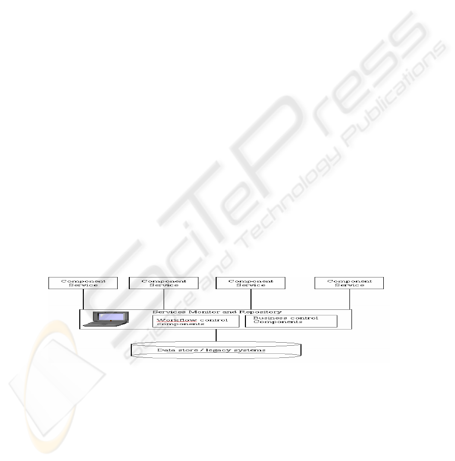
Services
Sub-Services
Workflow Processes
Sub workflow -Processes
O
bj
ects
Isolation
Services
Sub-Services
Workflow
Sub
w orkflow -
Processes
O
bj
ects
Inte
g
ration
N
ew sub workflow
Fig. 2. Isolation replacement and integration of new workflow
22
Process and transaction framework contains an underlying java Foundation made
of fundamental data structure implementations and utilities used throughout the rest of
Enterprise processes. Examples include arrays, dictionaries and formatting classes.
These processes provide RDBMS independence for services persistence, provides
object persistence transaction management, and provides services useful for web
based presentation and deployment. It also provides an environment to use and create
reusable components; it facilitates the use of true business objects in services oriented
framework and handles storing and restoring objects to a data store and usually in a
relational database. Since the business processes and objects created don't care about
the underlying database or how their values are presented in user interfaces, they may
be re-used over and over in any number of different web applications and can be
maintained by developers. Web services framework also provides a persistence layer
to maintain information at all time.As a single process can produce a huge workflow
map, the subworkflow layers allow the workflow to be broken down into more
manageable sections. This also allows modularisation of commonly used functions –
for example bulk notification activities rather than having them repeated throughout
the main map or even several workflows maps or systems. This also makes them
easier to manage and maintain. Sub workflow layer can be very useful to split your
main process into its constituent elements – in a large process there is likely to
produce a quicker initiation and processing. However, in some cases, the overhead of
moving from a ‘parent’ workflow into a ‘child’ sub workflow can be a lot higher than
the performance benefit of doing so, hence we need to plan the workflow carefully.
This type of architecture will help in bringing about main areas of changes like:
Services Layer changes like criteria determining field colouration or visibility or
edibility of a given field has changed, or a popup box is now required if some criteria
is met.
• Data Changes / Mass Updates like Value Added Tax calculations need to be
redone if VAT rate changes, customer name changes
• Business Logic changes like Logistic criteria changes, routing requirements
change.
• Patches / Bug Fixes that need to be applied to many active workflows
Fig 3. Implementation Framework
One approach is to suspend, correct and restart each workflow in sequence,
although for large numbers of workflows this would be very time consuming [18].
23

7 Frameworks For Services Components And Implementation
We propose use of a modular approach to software development for implementation
of this model, current advancement in technology has resulted in better quality,
reusability, productivity, and cost effectiveness. Changes to the system composition
and configuration are limited once the system has been compiled. In order to solve the
complexity and flexibility issues of large-scale software, We encapsulate business
logic in a workflow, and use component based middle layer called Services Monitor
and Repository which acts as a centralized server that contains all diagrams, reports,
forms, data structure, data definitions, process flows, logic, and definitions of
organizational and system components; it provides a set of mechanisms and structures
to achieve seamless data-to-tool and data-to-data integration, this middle ware
provides the link between Component Services and data store. This services monitor
and repository layer follows strict object oriented principles, it contains two major
parts, workflow control components and Business control components which contains
all the objects that execute the complex business rules. In data store large complex
workflow processes are broken down into smaller workflows and sub workflow layers
to be able to better manage and maintain each section. Some process activities may be
repeated throughout the main map or even several workflows maps or systems. This
allows modularization of commonly used functions and help in easy management by
Services Monitor described in detail below. Data store shown in Figure 2 aims to
eliminate latency by allowing multiple applications to access a single physical data
store directly. This architecture is suitable when applications and databases are
located in the same data centre; this approach is more intrusive because we usually
have to modify some applications to use a common schema. Reading data directly
from a database is generally harmless, but writing data directly into an application's
database risks corrupting the application's internal state.
Although transactional integrity mechanisms protect the database from corruption
through multiple concurrent updates, they cannot protect the database from the
insertion of bad data. In most cases, only a subset of data-related constraints is
implemented in the database itself. [20]. To avoid this we include Services Monitor
which is visual tool mapping software which is part of the services monitor and
repository layer, we use component technology for data management in order to
extract the underlying schema in the datastore which is also in the form of
components. Services monitor allows us to identify the workflow processes and sub
workflow processes and objects stored in the data source, which need to be isolated
and a new sub workflow which has to be integrated, it also helps to create, edit, or
delete existing
data store objects dynamically when connected to the datastore. We
can interact with the server data store using datastore diagrams incorporated in the
service monitor. Datastore diagrams graphically represent the tables as of a normal
database. These tables display the columns they contain, the relationships between the
tables, and indexes and constraints attached to the tables. We can use data store
diagrams to: View the tables in your database and their relationships. Perform
complex operations to alter the physical structure of the database.
We can make changes freely in the datastore diagram without affecting the
underlying datastore. When we modify a datastore object through a datastore diagram,
the modifications made are not saved in the datastore until we save the table or the
24

datastore diagram, Visualize the structure of your database tables and their
relationships. Provide different visualizations of complex databases. Experiment with
database changes without modifying the underlying database. Create new tables,
indexes, relationships, and other constraints. Alter the structure of your database.
Thus, we can experiment with "what if” and various workflow scenarios and also
check if these changes made to the workflow can be integrated to the existing
workflow, using a datastore design without having to permanently affect its existing
design or data. During editing, we can experiment with different object definitions to
see if proposed modification will affect the datastore. When we complete these
modifications, we can either save our diagram/design or update the database to match
the diagram, or we can discard it leaving the underlying database unchanged.For
example [please refer to figure 4], you can create/view a database diagram for
customer services department that shows only tables that hold local delivery of goods
information. We can view workflow part of the process that shows only those tables
that are used in this specific workflow module, here we can make change to
Devanning process to replace Warehouse code with Warehouse type code and
Delivery docket with Delivery time. We can change the size, shape, and position of
objects in the diagram without affecting their definitions in the database. When we
save the datastore diagram, the layout of the diagram is preserved as well as any
changes made to the object definitions in the diagram are also saved.
U
p
vannin
g
Web-Services
Customer services
Local Deliver
y
Ex
p
ort
Devanning
Goods type
Picku
p
schedule
Deliver
y
docket
Warehouse code
Fig. 4. Example of local delivery process
So as to keep the whole consortium process running we propose exclusive locking
mechanism; the locking level Performance and concurrency can also be affected by
the locking level used, Exclusive locks are exclusive to the user till the changes are
made without having to dissturb the overall workflow. Exclusive lock on a record
means that part of the process is denyed access, there by that part of the workflow is
isolated so that the required changes can be made only to that part of the process, one
may choose some objects or even all of the workflow or sub workflow tasks to be
associated with implicit invocation. determines the size of the process that is locked.
[21]. This framework is applicable to a diverse range of software Performance and
concurrency can also be affected by the locking level used, Exclusive locks are
exclusive to the user till the changes are made without having to dissturb the overall
workflow. Exclusive lock on a record means that part of the process is denyed access,
there by that part of the workflow is isolated so that the required changes can be made
25
only to that part of the process, one may choose some objects or even all of the
workflow or sub workflow tasks to be associated with implicit invocation. When
editing of table in a datastore diagram has been done, an asterisk (*) Example
Delivery time *, appears after the table name in the title bar to indicate that the table
contains changes to the workflow that have not yet been saved in the database. This
indicator appears as a result of a change made to the workflow objects in the
datastore, represented as a
column or index, in the table of the diagram/ design. When
we add a modified table to another open diagram, the table appears there with its
unsaved changes and an asterisk in its title bar. When you save the table or the
diagram, the asterisk disappears.
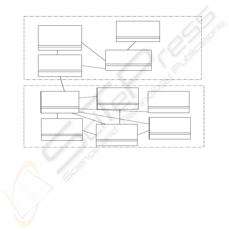
Component Services Layer
User Data
Service tier Component
EventListData
InformationData
Loc aldeliveryView
Service tier Component
Service tier Component
Service tier Component
Middleware
RemoteServicesManager
EventListManager
DatabaseAccess
WorkflowControl
Manager
BusinessControl
Manager
dotcom
dotcom
dotcom
ServicesRepositoryComponentsLayer
data management
data management
data management
Fig. 5. Example of component design for our services
This reconfigurable plug and play object component-based framework [please
refer to figure 5] is used to specify collaborative software construction, customization,
integration and evolution through the reuse of context-independent objects where
composite architectures are hierarchically constructed from layered groups of
collaborating component plug-ins development environments.
For user interface web services layer browsers interact with HTTP servers in their
normal way taking advantage of any technologies that enhance this browser-to-web
server link. For example secure socket layer communication protocols in Netscape
and Microsoft browser/server products browsers communicate with HTTP servers,
which communicate with the Application Server. The Business web services layer
generates web application at run time, Services communication layer provides
application’s user interface, state management and provides an environment to use
26

and create reusable components [7]. business logic is separated using two tier
approach, web services are generated at runtime from metadata in the services
repository component layer, this middleware data describes the webservices and its
interaction with the underlying business logic components [22]. This procedure helps
us to have multiple user services configuration based on shared business and
workflow logic components.
8 Conclusion
In this paper, we have discussed service oriented architecture for dynamic workflow
systems. We have also discussed issues and frameworks, service oriented enterprises
systems and have come up with approach for dynamic adaptation of the changes to
the existing workflow. We propose implementation of such systems by the process of
isolation, integration and synchronization, our future research will be to implement
this plug and play software development methodology and come up with a working
prototype of our system.
References
1. Marshak, R.T 1994.: “Falling in Love with Distinctions”, In “New Tools for New Times:
The Workflow Paradigm”, Future Strategies Inc.,
2. Miers, D 1996: “The Workware Evaluation Framework”, Enix Limited,
3. Chang, E 2000: Requirement Specification of Logistic Manager for Software Engineering
Project, Department of Computer Science and Software Engineering, The University of
Newcastle,.
4. Haake, J.M., Wang, W. 2002: “Flexible Support for Business Processes: Extending
Cooperative Hypermedia with Process Support”.
5. Denning, P.J.,1994 “The fifteen level”, In Proceedings of ACM SIGMETRIC Conference
on Measurement & Modeling of Computer Systems.
6. Sheth A 1996..: “State-of-the-art and future directions”, In Proceedings of the NSF
Workshop on Workflow and Process Automation in Information Systems.
7. David Neumann, 2004. An Introduction to WebObjects. Retrieved:July30,from
http://.mactech.com/articles/mactech/Vol.13/13.05/WebObjectsOverview.
8. Pudhota L, Chang E. et al 2003,. International Journal, Computer Science, System and
Engineering, “Extension of Activity Diagrams for Flexible Business Workflow Modeling
“volume 18 no3 UK.
9. Pudhota L, Chang E 2004 “collaborative workflow management for logistics consortium”
ICEIS Porto, Portugal.
10. Pudhota L, Chang E 2004 “Modelling the Dynamic Relationships between Workflow
Components” ICEISl Porto, Portugal.
11. Pudhota L, Chang E, Venable J 2004 “E- Business technology adaptation through
workflow mining” MSV Las Vegas, Nevada, USA.
12.
http://www.omg.org/mda/mda_files/UNextMDA4.pdf
13. Ulieru. M, Robert W. Brennan Scott S. 2000 “The holonic enterprise: a model for Internet-
enabled global manufacturing supply chain and workflow management”, Canada.
14. Ulieru. M, Stefanoiu. D, et al2000.. “Holonic metamorphic architecture for manufacturing”
University of Calgary, Calgary, Canada
27

15. Brandenburger, A. M. and Nalebuff, B. J., 1996, Co-operation, Doubleday NY.Brennan, R.
2000, “Performance comparison and analysis of reactive and planning-control architectures
for manufacturing”, Robotics and Computer Manufacturing 16(2-3), pp. 191-200.
16. Christensen, J.H, 1994 “Holonic Manufacturing Systems: Initial Architecture Standards
Directions”, Proceedings of the First European conferenceManufacturing systems,
European HMS Consortium, Hanover, Germany.
17.
http://www.journee.com/n_hl_020703b.html
18. Anastassia.A, Yannis E. et al 1998 “Scientific Workflow Management by Database
Management” book title = "Statistical and Scientific Database Management" pages = "190-
199",
19. Clark, M., Fletcher, P., et al 2002. Web Services Business Strategies and Architectures.
Expert Press.
20. Talevski, A., Chang, E., Dillon, T., 2003 “Overview of a Plug and Play Component-Based
Framework”, World Multiconference on Systemics, Cybernetics and Informatics, Orlando,
Florida, USA.
21. Maloney, J., “COM Reality Tour”, Microsoft Cooperation. On-line at:
http://www.microsoft.com/com/ August 1997
22. T. Andrews, F. Curbera etc.: Business Process Execution Language for Web Services
Version 1.1. http://www-106.ibm.com/developerworks/webservices/library/ws-bpel/, May
2003.
28
