
A VIDEO DELIVERY METHOD USING AVAILABLE BANDWIDTH
OF LINKS WITH BUFFERS AND DISKS
Hideaki ITO
Graduate School of Computer and Cognitive Sciences, Chukyo University
101 Tokodachi, Kaizu-cho, Toyota, 470-0393, Japan.
Teruo FUKUMURA
Graduate School of Computer and Cognitive Sciences, Chukyo University
101 Tokodachi, Kaizu-cho, Toyota, 470-0393, Japan.
Keywords:
Video delivery, resource allocation, link bandwidth, available bandwidth, delivery scheduling.
Abstract:
Scheduling policies and methods are required to deliver videos through network structure since the videos
are key contents, and they are continuous media, in order to design the networked multimedia systems. These
systems allocate resources before video clips leave their servers for guaranteeing continuous play of the videos.
The policies for achieving video delivery play an important role in sense of effective delivery. The method
for utilizing the links is a momentous problem, since their capabilities are restricted, and extensions of their
capabilities are a difficult issue. The policy shown in this paper is that available network bandwidth is used for
delivering one video clip at once. The bandwidth of a link is exclusively used to deliver only one video clip.
On the other hand, buffers and disks are established easier than the links. Moreover, some simulating results
are shown. Then, the amount of buffer space is restricted, and disks are used for storing the video in temporal.
1 INTRODUCTION
In recent, videos have been dealt with as primary con-
tents in networked multimedia systems(Dashti, 2000;
Hua, 2000). Such systems deliver videos through net-
work structure. Then several kinds of resources are
used to achieve this, scheduling of link utilization is
one of vital problems for designing the systems.
From the viewpoint of the utilization of restricted
link bandwidth, there are two types of methods(Ito,
2004). One is that a video clip is transmitted by using
link bandwidth as much as possible; the other is that
a video clip is transmitted as little as possible. The
former is the method that an entire link bandwidth is
used for delivering only one video clip, the latter is
that a minimum bandwidth is used. These two de-
livery methods are called the available bandwidth de-
livery method and the minimum bandwidth delivery
method, respectively.
In the available bandwidth delivery method, an en-
tire link bandwidth is used for transmitting only one
video clip. While the video clip is transmitted through
a link, this link is exclusively used to achieve this
transmission. Also, there is the case that there is dif-
ference between bandwidths of two links which are
connected to intermediate servers. At an intermediate
server, if the link bandwidth of the link used for re-
ceiving the video is broader than the link bandwidth
for sending it to another server, buffer space is re-
quired to store overflowed video.
An algorithm for delivering videos is proposed by
(Zhang, 2000). This algorithm treats scheduling of re-
sources which are disk bandwidths and network band-
widths in sense of physical structure. Routing al-
gorithms are proposed by (Vogel, 1996), which sat-
isfy Quality of Services constraints. The method de-
scribed in (Won, 1999) treats the video placement,
and transmission costs of video clips. The method
shown in (Shahabi, 2000) deals with transmitting
videos and buffering in servers. An entire bandwidth
of a link is used for transmitting a video.
This paper is organized as follows. Section 2
presents an overview of a networked video delivery
system. An overview of scheduling with buffer re-
striction and with disks in Section 3. Some simulating
results are presented in Section 4. Finally, Section 5
presents some concluding remarks.
2 AN OVERVIEW OF A
DELIVERY MODEL
A structural overview of a model for delivering videos
is shown in Figure 1 from the viewpoint that a video
453
ITO H. and FUKUMURA T. (2005).
A VIDEO DELIVERY METHOD USING AVAILABLE BANDWIDTH OF LINKS WITH BUFFERS AND DISKS.
In Proceedings of the Seventh International Conference on Enterprise Information Systems, pages 453-456
DOI: 10.5220/0002548904530456
Copyright
c
SciTePress

video server
intermediate server intermediate server client
...
link link link
video
a set of video clips
buffer
disk
buffer
disk
Figure 1: An overview of a networked video delivering sys-
tem.
is delivered from a video server to a client site. A
video server and a client are connected by some links.
When a client requests to watch a certain video, the
requested video is delivered from the video server to
the client site through several intermediate servers.
The sequence which consists of a video server, some
intermediate servers and a client site, is called a de-
livery path which is used for delivering a requested
video clip. The intermediate server consists of links,
a disk and a buffer. The disk is used for storing re-
ceived video. Stored videos are kept in an intermedi-
ate server since the video is removed from the disk.
Stored video in the buffers is sent automatically and
implicitly, while stored video in disks are arrived and
are left explicitly in sense that they are scheduled.
For delivering video, costs are computed. The costs
are defined from two viewpoints. One is related to
quality of the delivery path in sense of Quality of Ser-
vices(QoS), another is related to usage costs of re-
sources. These costs are called a quality cost and a
charge cost, respectively. The quality cost is speci-
fied in failure rate, packet loss ratio, and delay time
of intermediate servers and links. The quality costs of
paths are computed as the follow expression;
cost
quality
(path) = W
F R
× FailureRate
+ W
P L
× PacketLoss
+ W
DT
× DelayTime
FailureRate, PacketLoss and DelayTime are QoS pa-
rameters. While, W
F R
, W
P L
and W
DT
are their
weights.
A charge cost of a delivery schedule is computed
as the follow way;
cost
charge
(s) =
X
i
C
link
i
× LinkUsageTime
i
+
X
j
C
disk
j
× DiskUsageTime
j
+
X
k
C
buffer
k
× BufferUsageSpace
k
s is a schedule. C
link
i
, C
disk
j
and C
buffer
k
are unit costs
for using each link i, disk j and buffer k of a schedule,
respectively. Costs of links and disks are charged for
their usage times. A unit cost for a buffer is charged
to the amount of utilized buffer space.
3 A SCHEDULING METHOD
WITH BUFFERS AND DISKS
The policies to construct schedules are as follows;
• An entire link bandwidth is used for delivering one
video clip. During this delivery the link is utilized
exclusively.
• The first video clip of a certain video leaves from
its video server, as soon as possible, if the quality
costs of paths are the same.
• The usage of buffers takes precedence over the us-
ages of disks.
• When the disk is used for storing a video tempo-
rally, the video is stored into the intermediate server
nearby a client than a video server.
Schedules are constructed in the following way. At
first, when a request occurs at client site, paths from
video servers to the client are obtained for each video
clip of a requested video. These paths are called can-
didate paths for delivering video clips.
Next, a delivery path is selected among candidate
paths by using a certain strategy to decide the delivery
path. There are three strategies. They are;
• Departure time effective strategy. The first video
clip departures from a video server as soon as pos-
sible.
• Quality cost effective strategy. The path whose cost
is the lowest among a collection of candidate paths
is selected preferentially than others. The quality
cost is measured in cost
quality
(path).
• Score effective strategy. The collection of candi-
date paths is ordered based on their scores. Scores
of the paths are calculated in terms of their quality
costs and their initial latency times when candidate
paths are used to deliver clips.
Finally, departure times of the consequent video
clips of the requested video are computed conse-
quently.
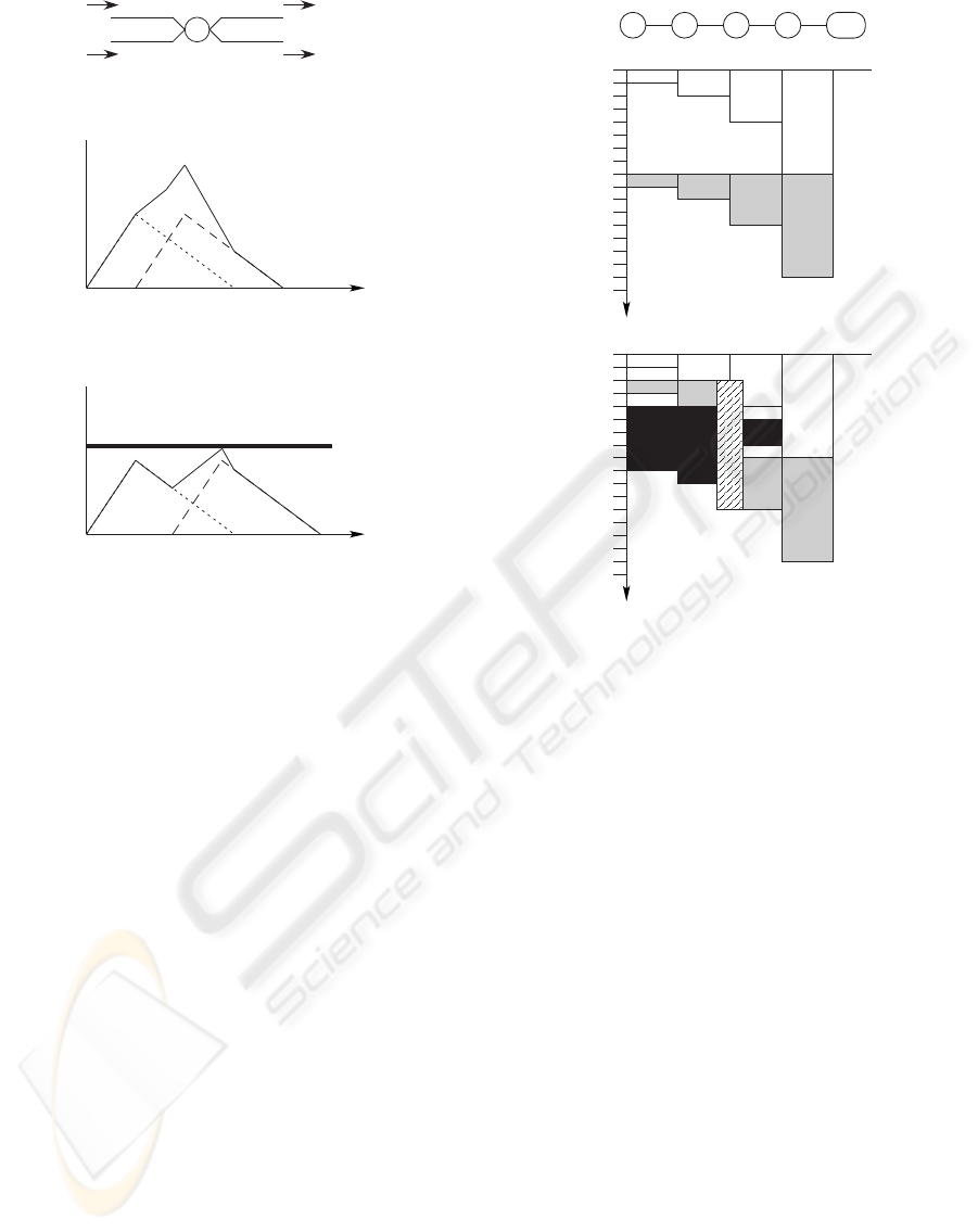
Figure 2 (a) shows a simple network structure, in
which there are one intermediate servers IS, and four
links, I1, I2, O1 and O2. Let the bandwidth of I1 and
O1 are a [Mbps] and b [Mbps], a > b, respectively,
and a video clip be delivered from I1 to O1, whose
size is M [Mbyte]. In (b), the short dotted line shows
the required buffer size of the intermediate server.
The maximum required buffer size is computed as:
the maximum required buffer size = (a − b) ∗ M/a.
On the other hand, there is the case that an interme-
diate server is connected to some servers and client
ICEIS 2005 - DATABASES AND INFORMATION SYSTEMS INTEGRATION
454
IS
I1
I2 O2
O1
(a) An example of an intermediate server.
required buffer space
time
required buffer space
time
(b) Required buffer space in an intermediate server.
(c) Required buffer space in an intermediate server
and restricted buffer space.
limit
t
1
t
2
Figure 2: Required buffer space in an intermediate server
and restricted buffer space in the intermediate server.
sites. For example, input streams of the intermedi-
ate server are I1 and I2, and output streams are O1
and O2, as shown in Figure 2 (a). In (b), a short dot-
ted line and a long dotted line show required buffer
size to transmit I1 to O1, and I2 to O2, respectively.
Required buffer space for delivering these two video
clips is shown in a solid line. If the buffer of the inter-
mediate server is unlimited, these two video clips are
able to be delivered. However, if the buffer space is
restricted, the arrival time of the clip using I2 and O2
is shifted to t2 from t1 as (c).
The scheduler tries to make a schedule which uses
disks, when it is impossible to deliver video clips due
to buffer overflow. Figure 3 shows an example of time
schedule using disks. A delivery path is shown in
Figure 3 (a). This path consists of the video server
(VS), three intermediate servers (IS1, IS2, IS3) and
the client site (Client). The client requests the video
which consists of two video clips. The time schedule
which is shown in (b) is constructed in the simplest
way. The time schedule for delivering the first video
clip is shown in the white squares, the time schedule
for the second clip the gray squares, respectively.
Figure 3 (c) shows the time schedule using a disk.
Black squares show the region which is allocated
for delivering some other videos than the requested
VS IS1 IS2 IS3 Client
time
(a) An example of a delivery path.
(b) An example of time schedule.
t0
t1
t2
t3
t4
t5
t6
t7
t8
t9
t10
t11
t12
t13
t14
t15
t16
t17
t0
t1
t2
t3
t4
t5
t6
t7
t8
t9
t10
t11
t12
t13
t14
t15
t16
t17
(c) An example of time schedule with a disk.
Figure 3: An example of time schedule using disks.
video. The first video clip is delivered by the same
time schedule shown in (b). However, the second clip
is not able to be delivered in the same way shown
in (b). Because, the region which is required to de-
liver the second video clip had been allocated to de-
liver other clips. In this case, the second video clip
is able to be delivered without skew time and without
increasing the initial latency time by using the disk
which is provided in intermediate server IS2. Also,
the scheduler tries to use the disk of IS3, however to
use this disk is difficult since the time interval that
is required to deliver the clip by the link between
IS2 and IS3 is not sufficient for delivering the second
video clip.
To prevent the occurrence of skew time, the sec-
ond video clip has to arrive to the client site by t8.
The link between IS2 and IS3 is able to be used for
delivering the second video clip. However, the links
between VS and IS2 are not used for its delivery. On
the other hand, the links between VS and IS2 is able
to deliver the clip for [t2, t4]. The video clip which is
transmitted using the interval [t2, t4] is stored into the
disk of IS2. At t8 this stored video in IS2 is delivered.
The client receives the second video clip without the
skew time. The striped region of this figure (c) depicts
the usage time of the disk in IS2.
A VIDEO DELIVERY METHOD USING AVAILABLE BANDWIDTH OF LINKS WITH BUFFERS AND DISKS
455
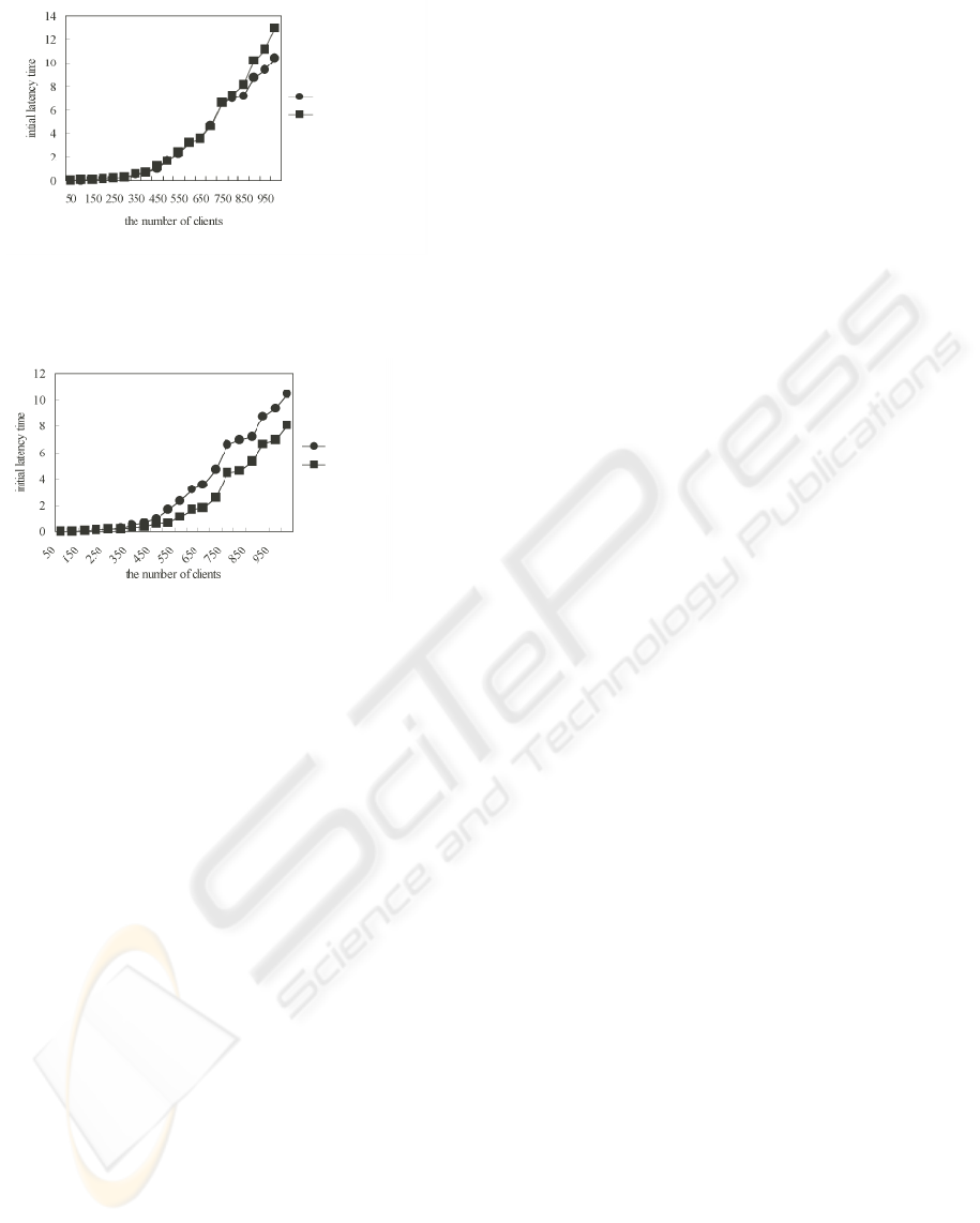
with buffer restriction
without buffer restriction
Figure 4: Initial latency time of schedules with buffer re-
striction.
without usage of disks
usage of disks
Figure 5: Initial latency time of schedules with disks.
4 SOME SIMULATION RESULTS
Some simulating results are shown by making some
assumptions. At fist, the network structure is as-
sumed. There are three video servers, nine intermedi-
ate servers, and links connecting servers. Each video
server is connected to one intermediate server. Ca-
pabilities of links are several tens and/or several hun-
dreds bandwidth [MByte]. The bandwidth of the links
between a video server and an intermediate server are
several hundreds. The client sites are connected to in-
termediate servers. Moreover, the size of each video
is 40 [MByte]. All videos consist of two video clips
whose size is 20 [MByte], and their consuming ratios
are 1 [MBps]. These two video clips are stored in the
same server. Furthermore, the requests occur during
100 seconds. The request times are generated as uni-
form random variables.
The initial latency times of some schedules which
are made using the departure time effective strategy
are shown. Figure 4 shows the initial latency times, in
which two lines are shown. They are corresponding
to the initial latency times when the buffer space is
restricted, and when the buffer space is not restricted.
On the other hand, Figure 5 shows the initial latency
times whether the scheduler uses disks or not. The
initial latency times are reduced by introducing disks.
The efficiency for introducing the disks appears al-
though the number of clients is small.
5 CONCLUDING REMARKS
An overview of the method that the full bandwidth
of a link is used for delivering one video clip is de-
scribed. Then, the utilization of buffers and disks are
introduced. Now, we plan to extend the capacity of
the scheduler from the following viewpoint. Utiliza-
tion of bandwidths of links makes be more effective.
When the bandwidth of an output stream is larger than
a bandwidth of an input stream, the link of the output
stream is used in partial.
ACKNOWLEDGEMENTS
We would like to thank Ikoma, Y. and Naito, T. for
their cooperation to implement schedulers.
REFERENCES
Dashti, A.E., Kim, S.H., Shahabi, C., and Zimmermann,
R., (2000). Streaming Media Server Design, Prentice-
Hall, 2003.
Ghose, D., and Kim, H. J.,(2000). Scheduling Video
Streams in Video-on-Demand Systems: A Survey,
Multimedia Tools and Applications, Vol.11, No.2,
2000.
Hua, K., Tantaoui, M.A., and Tavanapong, W., (2004).
Video Delivery Technologies for Large-Scale Devel-
opment of Multimedia Applications, Proceedings of
the IEEE, Vol.92, No.9, 2004.
Ito, H. and Fukumura, T., (2004). On utilization of Availa-
bale Link Bandwidth and Minimum Link Bandwidth
in Video Delivery, Proc. CCCT, 2004.
Shahabi, C., and Alshayeji, M., (2000). Super-Streaming:
A New Object Delivery Paradigm for Continuous
Media Servers, Multimedia Tools and Applications,
Vol.11, No.1, 2000.
Vogel, R., Herrtwich, R.G., Kalfa, W., Witting, H., and
Wolf, L.C., (1996). QoS-Based Routing of Multime-
dia Streams in Computer Networks, IEEE J. of Se-
lected Areas in Communications, Vol.14, No.7, 1996.
Won, Y., and Srivastava, J., (1999). Strategic Replication of
Video Files in a Distributed Environment, Multimedia
Tools and Applications, Vol.8, No.2, 1999.
Zhang, Z.-L., Wang, Y., Du, D. H. C., and Su, D.,
(2000). Video Staging: A Proxy-Server-Based Ap-
proach to End-to-End Video Delivery over Wide-Area
Networks, IEEE/ACM Transaction on Networking,
Vol.8, No.4, 2000.
ICEIS 2005 - DATABASES AND INFORMATION SYSTEMS INTEGRATION
456
