
Using Timed Model Checking for Verifying Workflows
V
olker Gruhn and Ralf Laue
Chair of Applied Telematics / e-Business
⋆
Computer Science Faculty, University of Leipzig, Germany
Klostergasse 3, 04109 Leipzig, Germany
Abstract. The correctness of a workflow specification is critical for the automa-
tion of business processes. For this reason, errors in the specification should be
detected and corrected as early as possible - at specification time.
In this paper, we present a validation method for workflow specifications using
model-checking techniques. A formalized workflow specification, its properties
and the correctness requirements are translated into a timed state machine that
can be analyzed with the UPPAAL model checker. The main contribution of this
paper is the use of timed model checking for verifying time-related properties of
workflow specifications.
Using only one tool (the model checker) for verifying these different kinds of
properties gives an advantage over using different specialized algorithms for ver-
ifying different kinds of properties.
1 Introduction & Related Work
In recent years, interest in business process automation has raised. One reason for this is
that the concept of web services allows integrating web-based applications using open
standards.
Developing a large system using web services starts with specifying the flow of con-
trol and information between these services - the workflow. This task should be done
by domain experts. Different business process definition languages have been devel-
oped for specifying workflows, the most important ones are BPML, BPEL4WS, XPDL
and UML2 activity diagrams. An increasing number of software tools abstract from
the syntax of the business process definition language, allowing the business process
analysts who specify the workflow to use a graphical notation (for example BPMN).
It should be possible to eliminate errors (like deadlocks or missed deadline con-
straints) in a workflow specification at specification time. Model checkers are sophis-
ticated tools that are able to find exactly this kind of errors for a given system. What
remains to do is to translate the workflow specification and the requirement we are
interested in into the input language of a model checker.
Our paper shows how this ”translation” can be done. Similar approaches were pro-
posed by several other authors: [1] starts with an informal description of a business
process. This description is being translated into the input language of the NuSMV
model checker which can check basic properties like liveness and reachability. [2]
⋆
The Chair of Applied Telematics / e-Business is endowed by Deutsche Telekom AG
Gruhn V. and Laue R. (2005).
Using Timed Model Checking for Verifying Workflows.
In Proceedings of the 2nd International Workshop on Computer Supported Activity Coordination, pages 75-88
DOI: 10.5220/0002559500750088
Copyright
c
SciTePress

checks various properties of business process specifications modelled in Testbed, a
framework for business process reengineering. The business process specification can
be defined by business process analysts using the Testbed tool, while the model check-
ing must be done outside the tool by model checking experts. A follow-up paper [3],
identifies some patterns of properties for business process specifications. Queries about
these patterns are transformed automatically into an LTL formula, allowing people who
are not familiar with the details of model checking to test properties of the business
process specification based on these patterns. [4] translates business process models de-
fined in the XPDL language into the input language of the SPIN model checker in order
to check their properties.
In all these publications, the properties than can be checked by a model checker, de-
pends on logical order between activities, not on their timing. Other than these existing
approaches, we take into account time-related properties (deadlines etc.).
We give an example for checking very different workflow properties: structural cor-
rectness, resource constraints, deadlines and dependences between different activities.
In the overview below, we will refer to algorithms that allow to check these different
classes of properties. The main contribution of this paper is to exploit only one tool for
checking the different properties instead of using one algorithm to check the structural
correctness, a second one for verifying the deadlines and other ones for reasoning about
deadlocks, reachability or resource conflicts.
Scheduling of activities under resource constraints is a well-studied problem in op-
erations research, known as Resource Constraint Project Scheduling Problem (RCPSP).
The general problem - finding a feasible schedule for a set of activities such that the
time for completing the project is minimized - has shown to be NP-hard [5], therefore
different heuristic algorithms have been suggested for solving it [6]. Finding resource
conflicts in a given workflow is much easier than solving the RCSP. [7] presents an al-
gorithm to find such conflicts. (Our example workflow is based on the example used in
this paper.) This is done by simply finding the earliest starting time and the latest com-
pletion time of each activity. However, the dependencies between the activities are not
taken into account which leads to many false positives. Our model checking approach
gives a more accurate result than [7].
[8] discusses the use of timed automata for solving the scheduling problem, which
is also the key idea for our model-checking approach. [9] has expanded the net diagram
technique PERT to ePERT which can be used for workflow specifications.
Structural correctness can be verified using graph analyzing techniques [10,11],
which require the use of special-purpose nontrivial algorithms. Graph analyzing tech-
niques can also be used for answering ”basic questions” about reachability and depen-
dence between activities (”Will a receipt be sent for every order?”, ”Is it guaranteed that
no receipt can be sent if the ordered item is out of stock?” etc.)
With our model checking approach, such specialized algorithms for checking spe-
cialized requirements (resource constraints, structural correctness etc.) can be substi-
tuted by using only one tool that can be used for verifying different kinds of properties.
76

2 Definitions
2.1 Workflow Specification
The Workflow Managemant Coalition defines a workflow as the computerized facilita-
tion or automation of a business process, in whole or part[12]. A Workflow Management
System (WfMS) is defined as a system that completely defines, manages and executes
workflows through the execution of software whose order of execution is driven by a
computer representation of the workflow logic.
In order to be processed by a WfMS, a workflow has to be specified in a formal
language that can be executed by computers. This language must define the order of
activation of activities and the information flow between them.
Before we give a formal definition of a workflow, we have to introduce the basic
concepts:
An activity is a description of a piece of work that forms one logical step within
a process[12]. Activities are scheduled by a WfMS. Their execution order is specified
by transitions. In the simple case of a (sequential) transition between activities, one
activity completes and the thread of control is passed to another one, which starts. To
be able to define more complex business cases, we further need the control structures
AND-split, OR-split, AND-join and OR-join, with the usual semantics [12].
1
We define a workflow specification as follows:
Definition 1 A workflow specification is a 4-tuple (N, n
0
, f, T ), where:
– N is a set of nodes which is defined as the union N = A ∪ C, where A =
{a
1
, . . . , a
n
} is a finite set of activities and C = {c
1
, . . . , c
m
} is a finite set of
control nodes. Each control node is either an AND-split, an OR-split, an AND join
or an OR-join, which is denoted by the type function type : C → {as, os, aj, oj}.
– There are two distinguished nodes: The start node n
0
∈ A and the end node f ∈ A.
– T ⊆ (N \ {f}) × (N \ {n
0
}) is a set of transitions between the nodes, where:
If (a ∈ A) ∨ (a ∈ C ∧ type(a) = as) ∨ (a ∈ C ∧ type(a) = os), then there
exists one and only one node b such that (b, a) ∈ T . (These nodes have exactly one
predecessor.)
If (a ∈ A) ∨ (a ∈ C ∧ type(a) = aj) ∨ (a ∈ C ∧ type(a) = oj), then there
exists one and only one node b such that (a, b) ∈ T . (These nodes have exactly one
successor.)
The usual semantics apply: The workflow starts in its start node n
0
. During a work-
flow execution, activities are executed with respect to the transitions between them.
Split nodes allow us to specify concurrency and alternative and join nodes allow us to
specify synchronization between incoming flows. Finally, the workflow execution stops
when the final node f is reached.
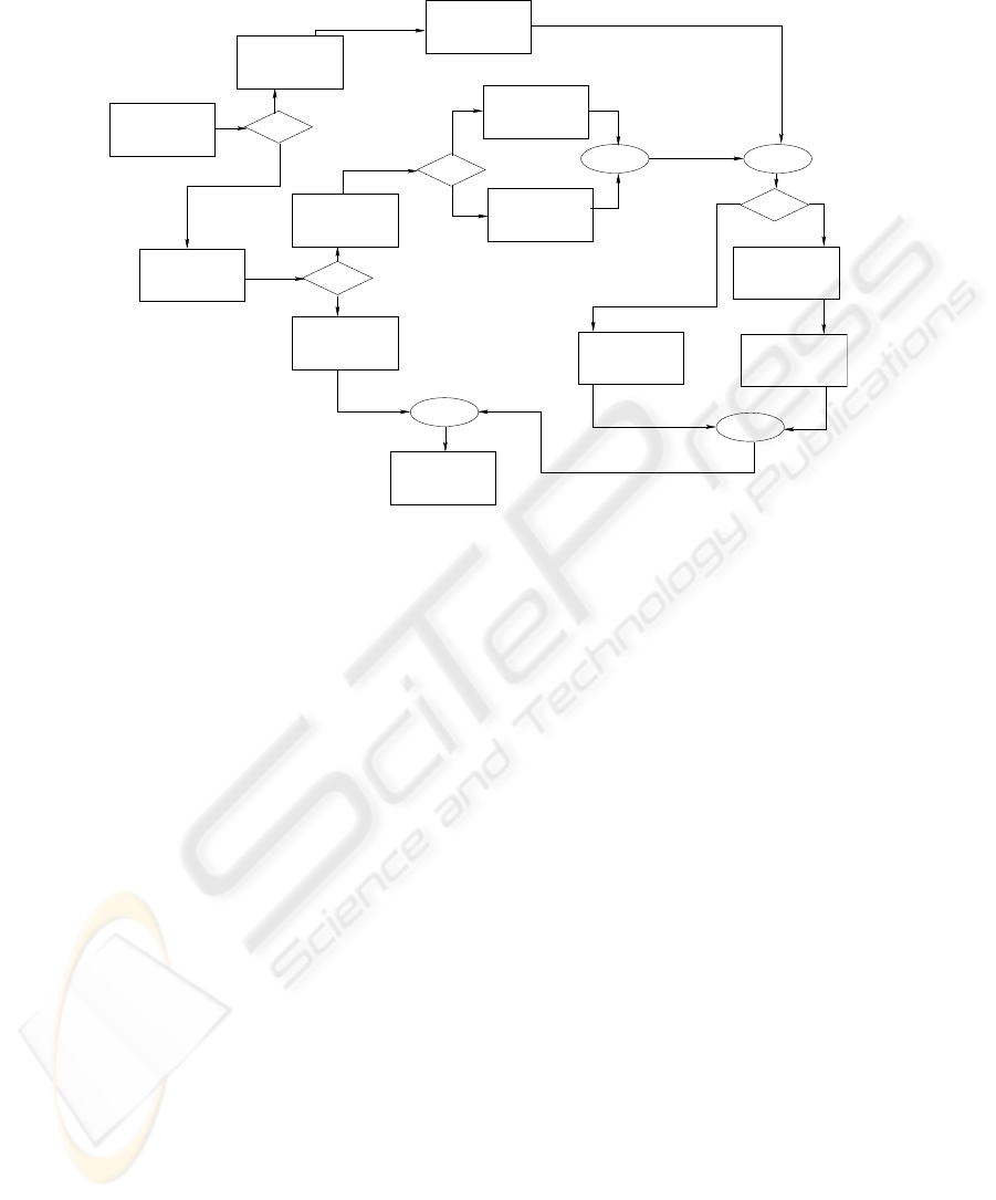
To illustrate a workflow, we use a simple graphical representation with these sym-
bols:
1
The name OR-split in [12] is a little bit misleading: XOR-split would be a better name, because
one and only one transition to the next node is selected.
77
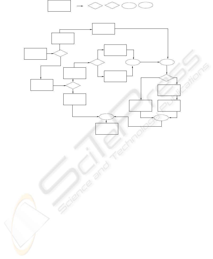
ORActivity 1 AND
AND
OR
Activity Transition AND−Split OR−Split AND−Join OR−Join
Signature from
Manager
Payment
Request
OR
Prepare Check
for ANZ Bank
Approval
from Finance
Director
OR
Reject
Request
for CITIBANK
Prepare Check
AND
Signature from
Finance
Director
Transfer Funds
to US−Account
AND
AND
Check
Issue
AND
Account
Update
Request
File
Payment
OR
US−$
A$
Approved
Rejected
OR
done
Fig.1. Sample workflow: Payment Requests
Split nodes have at least two outgoing transitions (arrows), while join nodes have at
least two incoming transitions. Outgoing arrows from an OR-split node can be labeled
with a short text describing a decision being made in the OR-split that leads to the
selection of one of the outgoing arrows.
Figure 1 shows an example workflow taken from [10] and [7]. It shows a business
process model for expense request payments with an option to differ between payment
in US-$ or in Australian $.
2.2 Structural Correctness
While def. 1 defines the syntax of a workflow specification, it does not say anything
about its semantics. Not every workflow specification that can be constructed using
definition 1 makes sense when the semantics for splits and joins is considered. An
example is shown in Fig. 2: Only one of the activities 2 and 3 will be performed after the
OR-split, but the following AND-join would wait for both activities being completed.
Even if the end node will be reached anyway via activity 1, it is very unlikely that this
is the behavior intended by the person who has specified the workflow. For this reason
it is reasonable to call such a workflow specification structurally incorrect.
78

OR
Activity 2
Activity 3
START NODE
Activity 1
AND
AND
END NODE
... (part after
the AND−join
omitted)
Fig.2. Semantically incorrect workflow
We will see later in this paper that structural correctness of a workflow can be de-
cided with our model checking approach. In fact, this is even possible without much
reasoning about possible sources of structural conflicts. We just have to take into ac-
count that the result of structural incorrectness is that either a possible execution exists
that does not reach the end node or there are still ”uncompleted things to do” when the
end node is reached. This leads us to:
Definition 2 A workflow specification w = (N, n
0
, f, T ) is structurally correct if
– every workflow execution reaches the end node f after a finite number of transitions.
– when the end node is reached, all other activities that have been started before are
completed and there are no remaining join nodes waiting for incoming transitions.
Because of the limited space in this paper, we omit the formal definition of ”a workflow
execution” and ”taking a transition”, but it should be intuitively clear what those phrases
stand for with respect to transitions and the semantics of split- and join-nodes
2
. Def.
2 simply requires that every sequence of nodes and transitions finally reaches the end
node f after a finite number of transitions, and there are no remaining join nodes waiting
for an incoming flow when the end node is reached. Infinite loops, AND-joins waiting
for an incoming flow infinitely long and similar problems must not occur. Sadiq and
Orlowska [13] have identified five types of possible structural errors in a workflow
specification. For all five types of errors, the workflow specification will be identified as
not being correct using def. 2 or it is already disallowed by the requirements for unique
predecessors and successors in def. 1.
2.3 Timed Workflow Specifications with Ressource Constraints
Activities can require human, material or machine resources, for example a director
who has to sign a bill (human resource), a vehicle to transport heavy goods (material
resource) or write-access to a database (machine resource).
2
The only point that needs some clarification is that activities after an OR-join should not be
activated more than once if more than one incoming flow reaches the OR-join. In this point,
the semantics used in this paper differs from the one used in [10]
79
Payment
Request
OR
Approval
from Finance
Director
Reject
Request
for CITIBANK
Prepare Check
AND
OR
AND
Check
Issue
AND
Account
Update
File
Payment
Request
Prepare Check
for ANZ Bank
Signature from
Manager
OR
Signature from
Finance
Director
AND
Transfer Funds
to US−Account
{r1, r7}
{r2, r7}
A$
US−$
Approved
Rejected
{r1, r3, r7}
{r6, r10}
{r3, r7, r10}
{r3, r8}
[1,3]
[1,2]
[4,6]
[4,8]
[2,3]
[1,2]
{r1, r3, r7}
{r4, r8}
[1,2]
[1,2]
[2,3]
done
OR
{r5, r8}
[3,8]
{r8, r9}
[1,2]
Fig.3. Workflow with information about time and resources
Often, these resources cannot be shared between different activities: When a work-
flow is executed, only one activity can access a resource exclusively.
This leads us to another possible source of incorrect workflow specifications: When
one activity needs a resource that is occupied exclusively by another activity, the work-
flow is deadlocked and cannot proceed. In real life, we can formulate the previous sen-
tence even more strictly: If the other activity occupies the required resource exclusively
until some deadline is reached, the workflow cannot be completed in time and hence
does not fulfill its purpose.
To find out whether such a situation can occur, we need to know something about the
usage of resources by the activities and about the duration of the execution of activities.
Definition 3 Let R = R
1
, . . . R
n
be a set of resources, which cannot be shared between
different activities. For each activity a ∈ A, r(a) is the set of resources needed by this
activity.
Definition 4 The minimum time (expressed in some time unit like seconds, hours or
days) that will be needed to execute an activity a ∈ A is denoted by m(a), the maximum
execution time will be denoted by M(a).
We call a workflow specification with the information about minimum and maxi-
mum execution time of its activities a timed workflow specification. This information
about timing is rather simple, but it has been shown to be sufficient for answering basic
80

questions about deadlines and resource conflicts (for example by applying the Criti-
cal Path Method [14]). Additional elements like an interrupt construct can be added if
necessary.
In Fig. 3, we add information about timing and resources to the graphical represen-
tation of the sample workflow. For each activity a ∈ A, m(a) and M(a) are given as
an ordered pair [m(a),M(a)] above the activity box, the set r(a) is given below the box.
Empty sets r(a) are omitted. We have taken this example from [7], with small modifica-
tions.
3 Model Checking of Timed Workflow Specifications
3.1 The Model Checker UPPAAL
To verify properties of a workflow specification, we use the real-time model checking
tool UPPAAL [15]. We show how to translate a workflow specification into a timed
automata specification that can be processed by UPPAAL.
An UPPAAL model is a set of timed automata, clocks, channels for handshake-
synchronization, variables and additional elements. Information about the syntax for
UPPAAL models can be found in [15]. Here we describe some elements only.
Each UPPAAL model is a set of processes (timed automata) which are depicted as
states (circles) and transitions (arrows) between them.
3
For each automaton, one state is marked as initial state (two concentric circles). A
graphic representation of an UPPAAL process can look like Fig. 4:
idle
logging in transferring data abort connection
Fig.4. Simple graphic representation of a process in UPPAAL
States can have the attribute ”committed”, depicted by the letter C inside the cir-
cle. If a state is marked as ”committed, no time may pass in this state, and it must be
left immediately (i.e. no interleavings with non-committed states in other automata are
allowed).
When a transition is taken, clocks can be reset. (In Fig. 5 the clock named clock1
will be reset to 0 when the transition from ”idle” to ”logging in” is taken), and global
or local variables can be manipulated. (In Fig. 5, a variable named active is changed
when the transition from ”logging in” to ”transferring data” or from ”abort connection”
to ”idle” is taken).
3
Note that the meaning of an arrow in the UPPAAL model is different from the meaning of an
arrow in the graphical workflow representation. Also a circle in the UPPAAL model does not
stand for an activity like the rectangle in the graphical workflow representation does. Instead,
one UPPAAL process (depicted by some arrows and circles) stands for an activity.
81

idle
logging in transferring data abort connection
clock1:=0 active:=1
active:=0
Fig.5. clocks, variables and an urgent location
Synchronization between different processes can take place using channels. When
a transition is taken, a channel can be written into (written as channelname!). To
achieve a handshake-synchronization, the corresponding reading operation (written as
channelname?) can serve as a so-called guard of another transition which can not
be taken unless reading from the channel is actually possible. If a channel is defined as
urgent channel, the reading operation must be performed as soon as possible, i.e. im-
mediately and without a delay. Fig. 6 shows a synchronization between a server process
and a client process:
idle
need new data accept upload
waiting uploading
listen!
listen?
Fig.6. Using channels for handshake-synchronization
Conditions on clocks or variables can also be used as guards for transitions. This
means that a transition cannot be taken until some condition (for example an equation
for some variable) holds. Finally, invariants can be added to a state. We will use invari-
ants of the type "clock<=m" which means that the system is not allowed to remain
in this state for more than m time units. In Fig. 7, the transition will be taken when the
clock named time is in the interval [2,4] and the value of the variable active fulfills
the equation active == 1.
state 1
time <= 4
state 2time >=2,
active == 1
Fig.7. Guards and invariants
82

3.2 Workflow Elements in UPPAAL
Using the elements introduced in the last section, we can define templates for the dif-
ferent kinds of nodes in a workflow specification (as defined in def. 1). Urgent channels
are used to model the transitions between the nodes.
Start Node The start node process does nothing else than writing into a channel
letsstart and setting the variable running (which stands for the number of cur-
rently running activities) to 0:
letsstart!
running := 0
Fig.8. Start Node
Activity Node The UPPAAL process for an activity node waits until it becomes acti-
vated by being able to read from a channel in channel. When it is activated, it sets
a local clock to 0 and increments the variable resource. The variable running (the
number of currently running activities) is incremented. After staying in the next state
for at least mintime, but not longer than maxtime, the process comes to and end which
it signalizes by writing to the channel out
channel. When the channel can be read
by another UPPAAL process, the variable running (the number of currently running
activities) is decremented.
AND-Split When activated (by the ability to read from in
channel), the UPPAAL
process for an AND-split writes repeatedly to the channel out channel, thus being
able to activate more than one following node. For AND-splits with two incoming flows
as used in our definition, this happens twice.
OR-Split Other than the AND-split, an OR-split process writes to the channel
out
channel only once, thus only one following node can be activated by reading
from this channel.
AND-Join An AND-join process tries to read from two channels, in
channel1 and
in
channel2, and proceeds if and only if both of them are readable. (Note that it is
not required that in
channel1 is readable before in channel2. If in channel2
is the first of the two channels being readable, it just ”waits” and the reading operation
can be performed after in channel1 became readable as well.)
OR-Join An OR-join process tries to read from two channels, in
channel1 and
in
channel2. It proceeds if it can read from one of them.
83

working
processclock <= maxtime
finishedprocessclock >= mintime
ressource--
out_channel!
running--
in_channel?
processclock := 0,
ressource++,
running++
Fig.9. Activity Node
in_channel?
out_channel!
Fig.10. AND Split Node
in_channel? out_channel!
Fig.11. OR Split Node
in_channel1? in_channel2? out_channel!
Fig.12. AND Join Node
in_channel1?
in_channel2?
out_channel!
Fig.13. OR Join Node
End-node The UPPAAL process end stands for the end node. This process will reach
the status named finished at the end of the model’s execution.
finished
in_channel?
Fig.14. End Node
84

working
processclock <= maxtime
finishedclock9 >0 4
r8--
running--
a10_channel!
s6_channel?
clock9:=0,
r8++,
running++
Fig.15. ”Issue Check” - an instance of the Activity template
3.3 Translating Timed Workflow Specifications to UPPAAL Models
In the previous section we have shown how the general elements of a workflow specifi-
cation can be expressed as UPPAAL models. To ”translate” a special workflow specifica-
tion into an UPPAAL model, we make use of UPPAAL templates. The UPPAAL models
of workflow nodes given in the last section are regarded as templates. This means that
the names for variables, clocks and channels in the UPPAAL model are placeholders
(called parameters in UPPAAL). To define an instance of an activity, we use this tem-
plate with parameters as follows:
Activity(processclock, mintime, maxtime, resource,
in
channel, out channel), where
– processclock is a placeholder for a local clock variable,
– mintime and maxtime are placeholders for numeric constants,
– ressource is the placeholder for a name of a single resource (For the sake of sim-
plicity, we assume that each process uses at most one resource from the resource
set R. By adding more placeholders, we can easily expand our model to the general
case.)
– in
channel and out channel are placeholders for urgent channels,
To instantiate the model for an actual workflow activity from the template, the place-
holders are substituted by actual variables:
For example, the definition of the activity ”Issue Check” from the example shown
in Fig. 3 can be done by defining an instance of the template Activity as follows:
IssueCheck := Activity(clock9,4, 6, r8, s6
channel,
a10 channel); (compare Fig.15 with Fig.9). The activity ”File Payment Request”
can be defined as:
FilePaymentRequest := Activity(clock11,1, 2, r10,
a10
channel, a11 channel); Note that synchronization between the both ac-
tivities can take place using channel a10 channel, which replaces the parameter
out
channel in the ”Issue Check” activity, but in channel in the ”File Payment
Request” activity.
Instances of control nodes can be built from the template in the same way. If a
workflow specification is given according to def. 1, the translation to the UPPAAL model
can be done automatically. For each node, an instance of an UPPAAL template will
be generated. This means that in general, only one line of code will be added to the
UPPAAL model for each node in the workflow specification
4
. Split nodes with n > 2
4
plus declarations of used variables, channels and clocks and the information about the fact that
the instantiated process is part of the system.
85

outgoing transitions or join nodes with n > 2 incoming transitions can be transformed
into a sequence of n-1 split/join nodes with two outgoing/incoming transitions.
The complete UPPAAL model of our example workflow can be downloaded from
ebus.informatik.uni-leipzig.de/∼laue.
3.4 Checking the Correctness of Timed Workflows
Having built the UPPAAL model of the workflow, we can use the model checker to
verify the required properties. The property specification language used in UPPAAL is
a subset of Timed Computational Tree Logic (TCTL) ([16].) Properties that could be
checked include:
”The end node will always be reached” (part 1 of def. 2):
A<> end.finished
(The state ”finished” in the process end will always be reached). This property can be
checked to be true for our example workflow.
”When the end node is reached, no activities are waiting for being finished” (part 2
of def. 2):
A[] end.finished imply running == 0
This property can be checked to be true for our example workflow. (Note that running
will not be decremented until the outgoing channel can be written into.)
”There are no resource conflicts for resource r10”
A[] r10<2
Can be checked to be true. Note that this requires reasoning about time: There are
no resource conflicts, because ”Update Account” is always finished when the activity
”File Payment Request” starts. (Using the knowledge that ”Update Account” and ”File
Payment Request” are the only activities that use resource r10, we will get the same
verification result by checking the property A[] UpdateAccount.working +
FilePaymentRequest.working <2. This makes use of the trick that boolean
values like UpdateAccount.working are converted to numbers (0 or 1). We would not
need the variables r1,...,r10, which helps to reduce the state space of the model.)
”There are no resource conflicts for resource r8”
A[] r8<2
The model checker does not only finds out that the property is violated, it also gives
a counterexample: a resource conflict between the activities ”Signature From Finance
Director” and ”Transfer Funds to US-Account”
”If a request has been rejected, no check will be issued.”
RejectRequest.finished --> not IssueCheck.finished
Can be checked to be true.
”The whole process will be completed in no more than 30 time units”
A<> end.finished and clock1<30
To check this deadline constraint, we use clock1, the local clock of the first activity
”Payment Request”. It is started at the begin of the whole workflow. This property can
be checked to be true. If we replace ”30” by a smaller value, a counterexample of a
process that needs 29 time units to complete will be given.
86

3.5 Remarks
Resource Pools The approach can not only be expanded to multiple resources (if r(a)
has more than one element, the model just needs more placeholders for resources used
by activities), it can also be used for checking the usage of resource pools, for example
a database that allows up to 10 parallel connections. We would have to check a property
like resourcecounter<=10.
Abstraction The timed workflow specification can be transformed automatically into
an UPPAAL model which can be used as the input of the model checker. However, a
complete translation of the workflow specification, preserving all its properties, does
not necessarily have to be what we really want: Too many details in the model can lead
to too many states the model checker has to examine.
5
Instead of translating a work-
flow specification while preserving all its properties, it may be a good idea to do some
abstraction before by asking which parts of the system are relevant with respect to the
property being checked. If we check for resource conflicts for r10 in the example work-
flow, information about other resources can be ignored. In fact, even only the model
built from the very last part of the workflow (”Issue Check”, ”Update Account” and
”File Payment Request”) is relevant. Often, this abstraction can be done automatically.
4 Conclusion
The use of only one tool for verifying different kinds of properties (with or without tim-
ing information) and the simplicity of translating workflow specifications to UPPAAL
models are the main benefits from the results presented in our paper.
We have highlighted reasoning about structural correctness and resource constraints,
but using the given approach, various other properties of workflow specifications can
be checked as well. This includes the patterns identified in [3] and [17], including exis-
tence, absence, precedence and response patterns. In our further research, we will inves-
tigate such patterns, including patterns for time-related properties (see [18]). Another
direction of our work will be to enable the business architects who are responsible for
defining workflow specifications to specify such properties without a deeper knowledge
in model checking or temporal logics.
References
1. Koehler, J., Tirenni, G., Kumaran, S.: From business process model to consistent implemen-
tation: A case for formal verification methods. In: EDOC. (2002) 96–
2. Janssen, W., Mateescu, R., Mauw, S., Springintveld, J.: Verifying business processes using
SPIN (1998)
5
In general, models with a large number of clocks lead to a state-space explosion in timed model
checking. Please note, however, that this is not the case in our model (where each activity adds
a clock): When an activity is completed, its clock is not used actively in comparisons and
cannot lead to new states.
87

3. Janssen, W., Mateescu, R., Mauw, S., Fennema, P., van der Stappen, P.: Model checking for
managers. In: 5th and 6th International SPIN Workshops. (1999) 92–107
4. Matousek, P.: Verification of Business Process Models. PhD thesis (2003)
5. Blazewicz, J., Lenstra, J., Kan, A.R.: Scheduling subject to resource constraints. Discrete
Appl. Math. 5 (1983) 11–24
6. Kolisch, R., Hartmann, S.: Heuristic algorithms for solving the resource-constrained project
scheduling problem: Classification and computational analysis (1999)
7. Li, H., Yang, Y., Chen, T.Y.: Resource constraints analysis of workflow specifications. J.
Syst. Softw. 73 (2004) 271–285
8. Norstr
¨
om, C., Wall, A., Yi, W.: Timed automata as task models for event-driven systems.
In: Proceedings of the Sixth International Conference on Real-Time Computing Systems and
Applications. (1999) 182
9. Pozewaunig, H., Eder, J., Liebhart, W.: ePERT: Extending PERT for workflow management
systems. In: First EastEuropean Symposium on Advances in Database and Information Sys-
tems ADBIS. (1997) 217–224
10. Sadiq, W., Orlowska, M.E.: Analyzing process models using graph reduction techniques.
Information Systems 25(2) (2000) 117–134
11. Onoda, S., Ikkai, Y., Kobayashi, T., Komoda, N.: Definition of deadlock patterns for busi-
ness processes workflow models. In: Proceedings of the 32nd Annual Hawaii International
Conference on System Sciences-Volume 5, IEEE Computer Society (1999) 5065
12. Workflow Management Coalition: Terminology and glossary. Technical report, Workflow
Management Coalition (1999)
13. Sadiq, W.: On correctness issues in conceptual modeling of workflows (1997)
14. Hillier, F.S., Lieberman, G.J.: Introduction to operations research. Holden-Day, Inc. (1986)
15. Larsen, K.G., Pettersson, P., Yi, W.: UPPAAL in a Nutshell. Int. Journal on Software Tools
for Technology Transfer 1 (1997) 134–152
16. Henzinger, T.A., Nicollin, X., Sifakis, J., Yovine, S.: Symbolic Model Checking for Real-
Time Systems. In: 7th. Symposium of Logics in Computer Science, IEEE Computer Scienty
Press (1992) 394–406
17. Dwyer, M.B., Avrunin, G.S., Corbett, J.C.: Property specification patterns for finite-state
verification. In: FMSP ’98: Proceedings of the second workshop on Formal methods in
software practice, ACM Press (1998) 7–15
18. Gruhn, V., Laue, R.: Patterns for timed property specification. In: 3rd Int. Workshop on
Quantitative Aspects of Programming Languages (QAPL 05), Edinburgh, Scotland, April
2005, to appear. (2005)
88
