
Stateful Design for Secure Information Systems
Thuong Doan, Laurent D. Michel, Steven A. Demurjian and T.C. Ting
Department of Computer Science and Engineering
University of Connecticut
371 Fairfield Road, Storrs, CT 06269-2155, USA
Abstract. The unified modeling language (UML) has gained wide acceptance
for the design of component-based applications via diagrams (e.g., use-case,
class, sequence, activity, etc.) for representing functional requirements. How-
ever, UML is lacking in its ability to model security requirements, an increasing
need in today's applications. This paper presents and explains techniques that
support stateful application design for secure information systems, extending
the abilities of UML with role-based access control and mandatory access con-
trol. From a security-assurance perspective, we track all of the states of a design
to insure that a new state (created from a prior state) is always free of security
inconsistencies, with respect to the privileges of users (playing roles) against
the application's components. This paper examines the theory of our approach,
along with its realization as part of the software process and as incorporated
into Borland's UML tool Together Control Center.
1 Introduction
In the design, development, and maintenance of secure information systems, we be-
lieve that security issues must be addressed early and often in order to potentially
yield more precise and accurate security requirements. To address security during the
software process, our current research [8, 9] has focused on incorporating mandatory
access control (MAC) and role-based access control (RBAC) into the elements (ac-
tors, use-cases, classes, etc.) and diagrams (use-case, class, sequence, etc.) of the uni-
fied modeling language, UML [6]. In UML, while there are parallels between security
and UML elements, direct support for security specification [16] is not provided. Our
work [8, 9] has focused on the inclusion of RBAC and MAC by aligning the concept
of role with actor, and by adding security properties to use-case, class, and sequence
diagrams to capture MAC and RBAC characteristics, and lifetimes (i.e., the legal time
intervals of access to UML elements). As justification for our efforts, we cite the
works of [1, 2, 11, 14, 15, 20, 21] who have explored security and UML, and work in
semantic and ER data models with security extensions [18, 19, 22].
Our objective in this paper focuses on capturing critical security requirements for a
UML design while simultaneously tracking all of the security design states. Towards
this end, this paper provides a framework that utilizes functional programming nota-
tion and constraints to capture and track all security requirements over time, resulting
Doan T., D. Michel L., A. Demurjian S. and C. Ting T. (2005).
Stateful Design for Secure Information Systems.
In Proceedings of the 3rd International Workshop on Security in Information Systems, pages 277-286
DOI: 10.5220/0002563802770286
Copyright
c
SciTePress

in an approach to stateful UML design that can be checked against the security con-
straints of an information system. In the remainder of this paper: Section 2 reviews
background on MAC/RBAC, and recasts our previous work [8, 9, 10] using a func-
tional notation; Section 3 explores stateful UML design, introduces a functional model
of the design state space and actions, and presents constraints for MAC, RBAC and
lifetimes. Section 4 examines the safety concept, provides an example of the actions
that transform the design states, and introduces design-time and post-design checking;
Section 5 reviews our prototyping effort that uses Borland's UML tool Together Con-
trol Center; Section 6 contains related work; and Section 7 concludes this paper.
2 Background Concepts
In this section, we review background concepts on RBAC/MAC, and the extension of
UML integrated with RBAC/MAC security based on our prior work [8, 9, 10]. First,
in MAC (or Lattice-Based Access Control [17]), security levels (SL’s) forming a lat-
tice structure are assigned to each subject (clearance - CLR) and each object (classifi-
cation - CLS). The permission of the subject to perform some operation on the object
depends on the relation between CLR and CLS as dictated by: Simple Security Prop-
erty ("read down - no read up'') [3]; Simple Integrity Property ("write down - no write
up'') [5]; Strict *-Property ("write equal'') [17]; and Liberal *-Property ("write up - no
write down'') [3]. For examples, we use SLs: unclassified (U), confidential (C), secret
(S), and top secret (T) where U < C < S < T (linear order) for simplicity; but our theo-
retical model is applicable for general partial orders. In RBAC [7, 12, 23], roles are
assigned to users to specify the named assignments that those users can perform in the
organization. Each role is authorized to perform some operations on certain objects.
Our extensions to UML for MAC and RBAC involve actors, use-cases, classes, and
methods as realized in use-case, class, and sequence diagrams [8, 9, 10]. To accom-
plish this, we associate, with each UML element, an identifier, element kind, minimum
and maximum security levels, and lifetime (LT) as a duration in which the usage of
that element is valid. Formally, we denote Λ
ID
as the set of identification labels
(uniquely assigned to each element), Λ
EK
= {A, UC, Cl, M} as the set of element kinds
(actor, use-case, class, and method, respectively), and Λ
SL
as the set of security levels.
Let T be a set of discrete time of the form “year-month-day [hour:minute:second]” (as
a subset Cartesian product of sets of integers), a lifetime lt a time interval [st, et]
where et and st ∈ T are the start time and end time, respectively, with et ≥ st. We de-
note the set of lifetimes as I. A UML element x is a tuple (id, k, sl
min
, sl
max
, lt) ∈
Λ
ID
×Λ
EK
×Λ
SL
×Λ
SL
×I where id, k, sl
min
, sl
max
, and lt are its element identification, kind,
minimum and maximum security levels, and lifetime, respectively. For a class c: Cl,
we require c.sl
min
≤ c.sl
max
(since a class is a container of attributes and methods)
whereas for an element x of other kinds, we require only x.sl
min
= x.sl
max
= x.sl.
As an example, consider a Survey Institution that performs and manages public
surveys. After the raw survey data is collected, senior staff adds a survey header into
the database; senior or junior staff adds questions into the survey, may categorize
questions, or add a question category. Questions with sensitive content are restricted
to senior staff. Figure 1 depicts a use-case diagram for creating a new survey entry.
278
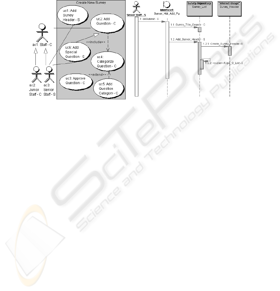
The actor ac1: Staff has two children ac2: Junior Staff and ac3: Senior Staff. Gener-
ally, Staff can perform uc2: Add Question which includes uc4: Categorize Question,
and can be extended to uc5: Add Question Category if a new category must be added
to the database. But, only Senior Staff can perform uc1: Add Survey Header to include
a new survey header entry and uc6: Add Special Question to include special sensitive
questions in a survey. Figure 2 illustrates a sequence diagram for Add Survey Header.
Fig. 1. UC Diagram: New Survey Entry. Fig. 2. Sequence Diagram: Add Survey Header.
To illustrate, uc1: Add Survey Header with min and max SL = Secret (S) and LT =
[“1/1/2005”, “12/31/2006”] is (uc
1
, UC, S, S, [“1/1/2005”, “12/31/2006”]). Formally,
we denote ∆ as the set of UML elements connected by different connection kinds, and
Λ
CK
as the set of connection kinds between UML elements x and y [8] (assuming use-
case diagrams and class diagrams are acyclic) as:
• Actor/Use-case (in use-case diagrams): (i.1). Actor inheritance A_Ih: actor x
inherits actor y; (i.2). Actor-use-case association AU_Asc: actor x interacts with
use-case y by association; (i.3). Use-case inheritance U_Ih: use-case x inherits
use-case y; (i.4). Use-case inclusion U_Ic: use-case x includes use-case y; (i.5).
Use-case extension U_Ex: use-case y extends use-case x.
• Class/Method (in class diagrams): (ii.1). Class inheritance C_Ih: class x inherits
class y; (ii.2). Class-method defining CM_Def: the method y is defined in class x.
• Combinations (in sequence diagrams): (iii.1). Use-case-class utilization
UC_Uz: class y is utilized in use-case x related to a sequence diagram; (iii.2).
Use-case-method utilization UM_Uz: method m is utilized in use-case x related to
a sequence diagram using m; (iii.3). Actor-method utilization AM_Uz: method m
is utilized by actor x; (iii.4). Method-method calling M_Ca: method x calls
method y (via message passing in a sequence diagram).
To track the security assurance of UML diagrams, each connection of a source and
target element (actor, use-case, class, etc.) is characterized by its connection kind and
LT. Formally, a connection is a tuple (x, y
, k, lt) ∈ ∆×∆×Λ
CK
×I where x, y, k, and lt are
the source and target UML elements, the connection kind, and connection LT. In
279

Figure 1, the connection from ac
3
: Senior Staff to uc1: Add Survey Header via asso-
ciation with LT=[“1/1/2005”, “12/31/2005”] is (ac
3
, uc
1
, AU_Asc, [“1/1/2005”,
“12/31/2005”]). Φ denotes the set of all UML connections for a design.
In support of RBAC, an actor (see Figure 1) represents one organizational role as
defined by the security officer. In [10], we specified three kinds of an application’s
security requirement (SR). First, Disallowed Usage (DisU) states that an element x
1
is
not allowed to use element x
2
. In Figure 1, the security policy prevents a junior staff
person from adding special questions and is specified with a DisU SR on the use of
use-case uc6: Add Special Question by the actor Junior Staff. Second, in Static Role-
Objects Mutual Exclusion (ME
SRO
) - the actor x
1
has a role prohibited from simultane-
ously using both elements x
2
and x
3
. Third, in Static Object-Roles Mutual Exclusion
(ME
SOR
) - actors x
1
and x
2
have roles prohibited from using element x
3
at the same
time. Let Λ
SR
be the set of security requirement kinds, an application’s SR of some
kind k may involve in as many UML elements as needed. In this paper, we limit a SR
as a tuple (x
1
, x
2
, x
3
, k) ∈ ∆×∆×∆×Λ
SR
where Λ
SR
= {DisU, ME
SRO
, ME
SOR
} as de-
scribed above. Θ denotes the set of SR instances.
3 Stateful UML Design
This section introduces a model that tracks states of UML elements, connections, and
security requirements (SRs) through transformations, and describe the process of
specifying security constraints for the design state. Intuitively, when the designer cre-
ates, modifies, or deletes a UML element, s/he changes the design to a new state that
only differs in its set of UML elements. Over time, a UML design can be character-
ized as the set of all states where each state represents a specific design iteration.
When the designer adds, modifies, or deletes an application’s SRs and UML connec-
tions, the design changes to a new state that differs in SRs or UML connections. A
design state is denoted by (
σ
∆
,
σ
Φ
,
σ
Θ
) where
σ
∆
,
σ
Φ
and
σ
Θ
respectively are the state
of designed UML elements, designed UML connections, and SRs.
With our approach, the design process reduces to a sequence of state transforma-
tions to add, update and/or delete UML elements, application SRs and UML connec-
tions. An action
α
(add, update or delete) maps state (
σ
∆
i
,
σ
Φ
i
,
σ
Θ
i
) into state (
σ
∆
i+1
,
σ
Φ
i+1
,
σ
Θ
i+1
) where the component states
σ
∆
,
σ
Φ
, and
σ
Θ
are represented with func-
tions. Intuitively,
σ
∆
is a function that associates each UML element and the design
time with a tuple of its name, element type, security levels, and lifetime (valid at that
the design time). The function for the initial empty component state
σ
∆
0
returns null.
σ
Φ
is a function that maps a pair of UML elements, a connection kind (for a connec-
tion), and the design time to the legality (valid or invalid) of the connection. The
function for the initial component state
σ
Φ
0
returns null to report the absence of con-
nections between any two UML elements.
σ
Θ
is a function associating a tuple of re-
lated UML elements, a SR kind (for an application’s security needs), and the design
time with the enforcement needed for that SR (at that design time). If the customer
requires enforcing that SR,
σ
Θ
is true, else
σ
Θ
is false (no enforcement).
σ
Θ
0
for the
initial component state is false to indicate that there is no SR needed by the customer.
280
A design state is captured with a triplet of first-class functions
σ
∆
,
σ
Φ
, and
σ
Θ
and
generated by an action based on the current state. Formally, the signatures of the three
functions are
σ
∆
: ∆×T → Λ
ID
×Λ
EK
×Λ
SL
×Λ
SL
×I;
σ
Φ
: Φ×T→ {valid, invalid, null}; and
σ
Θ
: Θ×T → {true, false}. An action
α
is a meta-function that produces the triplet of
first-class functions for the next state. Design reduces to an interleaving of actions to
produce a state (
σ
∆
i
,
σ
Φ
i
,
σ
Θ
i
) and evaluate its state function
σ
Φ
i
to determine its safety.
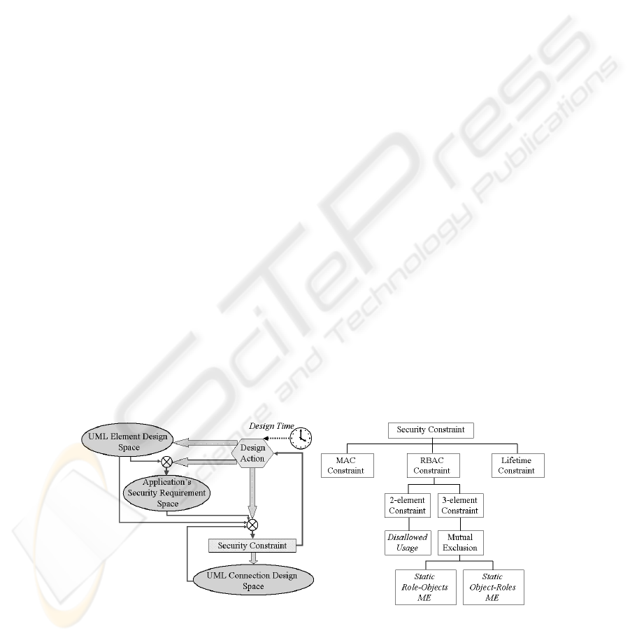
Figure 3 illustrates the methodological concerns via the space of three design state
components and their interactions at design time. Typically, the designer first creates
UML elements (transforming
σ
∆
). Next, s/he associates existing UML elements with
the application’s SRs (transforming
σ
Θ
) which can include disallowing an actor to use
some class, or specifying a static mutual exclusion of an actor to utilize two use-cases
at the same time, etc. Then s/he draws connections among UML elements (transform-
ing
σ
Φ
). The legality of a connection is checked based on the security constraints (see
Figure 4) of related UML elements, other existing connections, and the application’s
SRs at that instant of the design time.
A brief description of the constraints for MAC, RBAC, and LTs used to validate
UML connections (Figure 4) follows. Due to space limitations, only intuitive descrip-
tions of the constraints are provided.
• MAC Constraint. The MAC constraint checks the domination of the SL of the
source element x over the target element y depending on the chosen MAC proper-
ties (e.g., Simple Security). For details, please refer to our previous work [9].
• RBAC Constraint. Let (a,b) ∈ Φ
2
denote the existence of a connection between
UML elements a and b where Φ
2
is a transitive binary relation representing all of
the UML connections without concerning the connection kind and LT. Let con-
nectTo(b) denote the set of UML elements in the projection of the transitive clo-
sure of Φ
2
on b and connectFrom(a) denote the set of UML elements in the pro-
jection of the transitive closure of Φ
2
on a. The RBAC constraint for a new con-
nection x to y determines whether the application’s RBAC SRs hold between x
and y and between all the vertices w ∈ connectTo(x) and z ∈ connectFrom(y).
• Lifetime Constraint. The LT constraint for a design state at a design time t re-
quires that for any connection, t fall in the non-empty overlap of the LTs of the
connection and those of its source and target elements.
Fig. 3. Design State Space and Actions. Fig. 4. Taxonomy of Security Constraints.
281

4 Security Assurance Design Support
In this section, we demonstrate the use of the model and constraints (see Sections 2
and 3) to obtain a safe design state. We introduce the concept of safe design state and
demonstrate the way that a design state is transformed and checked against constraints
when actions are performed. The concepts are foundational for a secure assurance
design support program for checking the safety of states. The goal from a security
assurance perspective is to assist the designer in producing a safe design. A design
state (
σ
∆
,
σ
Φ
,
σ
Θ
) is said to be safe at design time t if every materialized connection of
kind k in
σ
Φ
between elements x and y in
σ
∆
evaluates to valid under SRs in
σ
Θ
(i.e.,
all of the connections of the design satisfy their MAC, RBAC, and LT constraints).
When a software engineer authors the use-case diagram given in Figure 1, s/he creates
new actors and use-cases and connects them with associations. Note that in our ap-
proach, the drawing of connections includes both security and functional characteris-
tics to allow us to be able to analyze security as connections are made.
To insure the absence of security errors, it is imperative that any actions taken by
the software engineer move the application from one safe design state to the next. To
illustrate this process, Table 1 provides a synopsis of the actions taken at design time t
= “06/01/2004” by a software engineer who: creates new UML elements - three use-
cases and three actors (States 1 to 6); adds SRs - a mutual exclusion (State 7); adds
two valid connections - one between actors and one between an actor and a use-case
(States 8 and 9); and fails in a connection attempt - from an actor to a use-case (State
10). The table omits the formal representation of actions, state functions, and con-
straints, to streamline the explanation and allow the reader to focus on the underlying
concepts. When the designer attempts to draw a connection from ac
1
to uc
3
, the con-
nection (ac
1
, uc
3
, AU_Asc t) evaluates to invalid in State 10 at design time t since the
application’s SR ME
SRO
has been added at State 7 (ac
2
is prohibited from simultane-
ously utilizing uc
2
and uc
3
). Then ac
2
inherits ac
1
(State 9) while ac
1
can utilize both
uc
2
and uc
3
in State 9. So, ac
2
can also utilize both and that violates the application’s
security requirement ME
SRO
. Hence, State 10 is not safe since the evaluation of func-
tion
σ
Φ
10
on ac
1
, uc
3
, AU_Asc, and t: (
σ
Φ
10
ac
1
uc
3
AU_Asc t) = invalid (and the secu-
rity assurance design support system reports an error message, see Section 5).
The security assurance framework supports two modes of checking: design-time for
real-time checks as the designer alters a UML diagram (as presented in Table 1 and
discussed above) and post-design for an on-demand check of an entire design version
(iteration) across all of an application's UML diagrams. Design-time and post-design
security safety checking are realized, algorithmically, as two parts of a Security As-
surance Design Support (SADS) program. SADS has two sub-programs: dSADS for
the design-time mode and pSADS for the post-design mode. Note that the dSADS
maintains the design in the safe state by preventing the UML design tool from materi-
alizing an invalid connection (see Section 5); thus we do not need to be concerned
with incremental deletion effect that would need to reconsider other connections.
To compare our model with other efforts, we make several observations. Assume
that two actors, ac
1
and ac
2
are mutually exclusive on use-case uc, and that we first
connect ac
1
to uc. A subsequent attempt to connect ac
2
to uc causes an error. Given
this scenario, [13] only supports post-design (akin to our pSADS) by creating a locally
282
stratified logic program from the authorization specification, and as a result, there is
only one connection allowed – assume that the ac
1
to uc connection is chosen by rule.
The approach of [4] only supports post-design, but provides all of the relevant alterna-
tives when conflicts are identified, and the designer can either choose ac
1
to uc or ac
2
to uc. Our post-design conflict checking aligns closely to [4]; it reports the ME con-
flict which can be resolved according to the designer’s preference. Our design-time
checking is also more robust since the conflict on the second attempted connection
(ac
2
to uc) raises the error. The main difference with [4, 13] is their use of logic pro-
grams with a fixed set of facts/rules as an authorization specification versus our use of
state functions to dynamically track/adjust for changing design states.
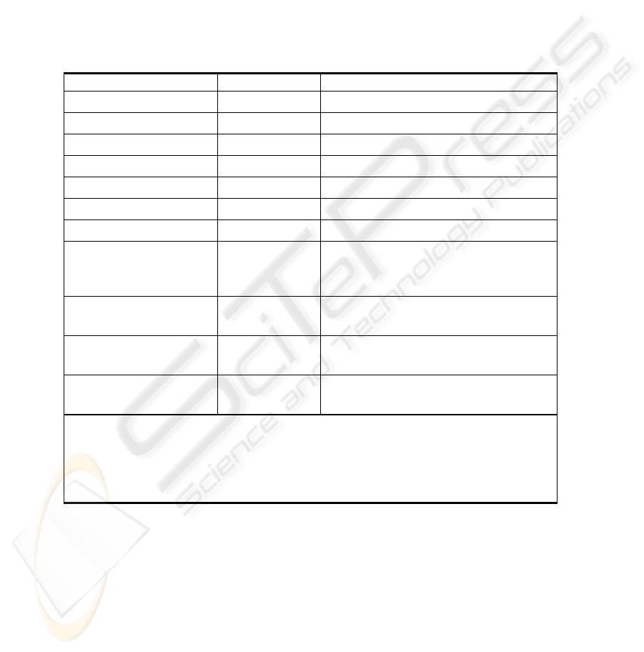
Table 1. Example of a Design State Construction Process
Attempted Action New State Effect
0:(
σ
∆
0
,
σ
Φ
0
,
σ
Θ
0
)
(The initial state)
Add uc
1
1:(
σ
∆
1
,
σ
Φ
1
,
σ
Θ
1
)
σ
∆
1
adds uc
1
,
σ
Φ
1
=
σ
Φ
0
,
σ
Θ
1
=
σ
Θ
0
.
Add ac
1
2:(
σ
∆
2
,
σ
Φ
2
,
σ
Θ
2
)
σ
∆
2
adds ac
1
,
σ
Φ
2
=
σ
Φ
1
,
σ
Θ
2
=
σ
Θ
1
.
Add uc
2
3:(
σ
∆
3
,
σ
Φ
3
,
σ
Θ
3
)
σ
∆
3
adds uc
2
,
σ
Φ
3
=
σ
Φ
2
,
σ
Θ
3
=
σ
Θ
2
.
Add uc
3
4:(
σ
∆
4
,
σ
Φ
4
,
σ
Θ
4
)
σ
∆
4
adds uc
3
,
σ
Φ
4
=
σ
Φ
3
,
σ
Θ
4
=
σ
Θ
3
.
Add ac
2
5:(
σ
∆
5
,
σ
Φ
5
,
σ
Θ
5
)
σ
∆
5
adds ac
2
,
σ
Φ
5
=
σ
Φ
4
,
σ
Θ
5
=
σ
Θ
4
.
Add ac
3
6:(
σ
∆
6
,
σ
Φ
6
,
σ
Θ
6
)
σ
∆
6
adds ac
3
,
σ
Φ
6
=
σ
Φ
5
,
σ
Θ
6
=
σ
Θ
5
.
Add a ME
SRO
to prohibit
ac
2
from simultaneous
use of uc
2
and uc
3
7:(
σ
∆
7
,
σ
Φ
7
,
σ
Θ
7
)
σ
∆
7
=
σ
∆
6
,
σ
Φ
7
=
σ
Φ
6
, and
σ
Θ
7
with a
Static Role-Objects Mutual Exclusion
SR on ac
2
with uc
3
and uc
2
.
Draw a connection from
ac
1
to uc
2
8:(
σ
∆
8
,
σ
Φ
8
,
σ
Θ
8
)
σ
∆
8
=
σ
∆
7
,
σ
Φ
8
with an association from
ac
1
to uc
2
,
σ
Θ
8
=
σ
Θ
7
. See Note 1.
Draw a connection from
ac
2
to inherit ac
1
9:(
σ
∆
9
,
σ
Φ
9
,
σ
Θ
9
)
σ
∆
9
=
σ
∆
8
,
σ
Φ
9
with inheritance from ac
2
to ac
1
,
σ
Θ
9
=
σ
Θ
8
. See Note 2.
Draw a connection from
ac
1
to uc
3
10:
(
σ
∆
10
,
σ
Φ
10
,
σ
Θ
10
)
σ
∆
10
=
σ
∆
9
,
σ
Φ
10
with invalid connection,
σ
Θ
10
=
σ
Θ
9
.
Notes: 1. The connection (ac
1
, uc
2
, AU_Asc) is valid in State 8 (at the design time t
= “06/01/2004”) as (
σ
Φ
8
ac
1
uc
2
AU_Asc t) yields valid - all three MAC, RBAC
and LT constraints hold at t.
2. The connection (ac
2
, ac
1
, A_Ih) is valid in State 9 as (
σ
Φ
9
ac
2
ac
1
A_Ih t) yields
valid - all three MAC, RBAC and LT constraints hold at t.
5 Model Architecture and Prototype Effort
Over the past year, we have been working on a prototype implementation that features
a model architecture that contains a set of interacting modules (see Figure 5):
• UML Design Tool is the graphical user interface (GUI) for the designer to in-
put/edit UML diagrams. Currently, we employ Borland's Together Control Center
283
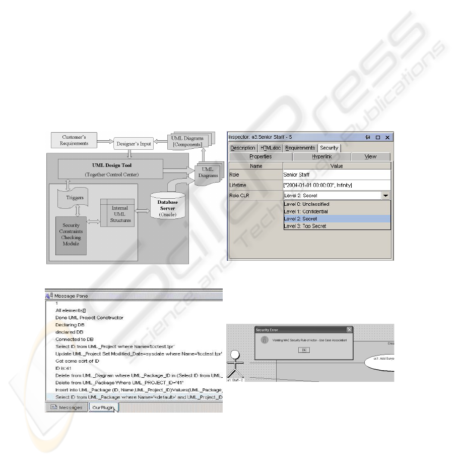
with Open APIs for Java and modular plug-in structure for UML design aug-
mented with security definition and both design-time and post-design checking.
• Internal UML Structures Storage stores in-core representations of UML struc-
tures extended with security properties and synchronously writes them to persis-
tent storage (an Oracle RDBMS) in order to improve searching capabilities and
support a multi-designer working environment.
• Security Constraint Checking Module enforces security constraints on UML
elements and connections. If a constraint is violated, it pops up an error message
and abandons the intended connection. Otherwise, the connection materializes in
the GUI UML design tool and updates the database.
Figure 6 shows a UML property dialog with a security page (enhanced with our own
custom code) that displays the clearance (CLR) for the Senior Staff actor as set to
“Secret” and lifetime. Figure 7 shows a Message Pane of the plug-in module listing
elements that have been created and SQL statements submitted to the RDBMS by
Java. Consider Figure 8 and assume that dSADS is enabled; an attempt to connect ac
1
:
Staff to uc
1
: Add Survey Header, triggers the display of an error message as the ac
1
.sl
= C < uc
1
.sl = S violates the MAC constraint.
Fig. 5. Our Model Architecture. Fig. 6. Security of Senior Staff.
Fig. 7. Message Pane of our Plug-in Module. Fig. 8. MAC Constraint Error Message.
284

6 Related Work
There have been other efforts on security for UML and other data models. First, in
[11] and [21], UML is used to represent RBAC modeling and notation. Next, in [20],
UML elements are used to model MAC and RBAC based systems. Both of these ef-
forts model security with UML, which contrasts to our approach to integrate RBAC,
MAC, etc., directly into UML, allowing applications to be built with security. Third,
UMLsec is an approach on formal analyses of multi-level security (secrecy and integ-
rity) of message flows in subsystems of UML (sequence/state diagrams) and extended
elements [14]. Our work on MAC is similar to theirs, and their flow analysis is akin to
our checking. Fourth, in [15], SecureUML has extended meta-model elements (e.g.,
User, Role, and Permission) and authorization constraints expressed to generate secu-
rity infrastructure for RBAC; this is similar to our constraints and checking of consis-
tency. Fifth, [1, 2] present a framework for incorporating security into use-cases,
which is more limited than our work which includes use-case, class, and sequence
diagrams. Sixth, in [22], a semantic data model for security is proposed, with con-
straints on security levels of data entities and relationships; this work is similar to our
efforts on MAC and the constraint checking as connections are made in UML dia-
grams. For ER models, [18, 19] have proposed extensions to represent security con-
straints among entities, again, similar to our efforts on MAC and constraint checking.
The major difference between [18, 19, 22] and our work is that their efforts have fo-
cused on multi-level security for attributes in the relational database paradigm whereas
ours is from an object-oriented approach of security levels for method level (to control
the behaviors of objects) with our inclusion of RBAC and lifetimes.
7 Conclusions
This paper has proposed a formal model for design states, actions for transforming
design states, and constraints on MAC, RBAC, and lifetime for UML connections.
Sections 2 and 3 presented a functional model to represent UML elements, UML
connections, and application security requirements, checking MAC, RBAC, and life-
time security constraints as changes are made to UML designs. Section 4 introduced
the concept of safety in this context, provided an example of the material of Sections
3, and described the Security Assurance Design Support Program for design-time and
post-design checking. Finally, Section 5 briefly reviewed the ongoing prototyping
effort of this work into Borland's UML tool Together Control Center, while Section 6
contrasted our work to related efforts in UML and semantic/ER data models. Our
ongoing work is in a number of areas. First, as a design grows in size, it may be rele-
vant to consider security definition and constraint checking on “meaningful” sub-sets
of the design. If the UML elements within a sub-set are closely related in terms of
security constraints but loosely affect elements in other sub-sets, it may be possible to
compartmentalize the security analysis. Second, we are exploring additions to our
constraint taxonomy, such as the Mutual Inclusion, location and dynamic constraints.
Third, there is a companion research effort that is exploring the use of aspect-oriented
programming to generate security enforcement code from our extended UML.
285

References
1. K. Alghathbar and D. Wijesekera. AuthUML: A Three-phased Framework to model Secure
Use Cases. Proc. of the Workshop on Formal Methods in Security Engineering: From
Specifications to Code, Washington D.C., 2003.
2. K. Alghathbar and D. Wijesekera. Consistent and Complete Access Control Policies in Use
Cases. Proc. of UML 2003, San Francisco, CA, LNCS, 2003.
3. D. Bell and L. La Padula. Secure Computer Systems: Mathematical Foundations Model.
M74-244, Mitre, 1975.
4. E. Bertino et al. A Logical Framework for Reasoning about Access Control. ACM Trans.
on Info. and System Security, 6(1), Feb. 2003, pp. 71-127.
5. K. Biba. Integrity Considerations for Secure Computer Systems. TR-3153, Mitre, 1977.
6. G. Booch, et al. The Unified Modeling Language User Guide. Addison Wesley, 1999.
7. S. Demurjian, et al. A User Role-Based Security Model for a Distributed Environment.
Research Advances in Database and Information Systems Security, J. Therrien (ed.), Klu-
wer, 2001.
8. T. Doan, et al. RBAC/MAC Security for UML. Proc. of the 18th Annual IFIP WG 11.3
Working Conf. on Data and Applications Security. Sitges, Spain, 2004.
9. T. Doan, et al. “MAC and UML for Secure Software Design”. Proc. of the 2nd ACM Wksp.
on Formal Methods in Security Engineering (FMSE’04). Washington D.C., 2004.
10. T. Doan, et al. UML Design with Security Integration as First Class Citizen. Proc. of the
3rd Intl. Conf. on Computer Science, Software Engineering, Information Technology, e-
Business, and Applications (CSITeA'04). Cairo, Egypt, 2004.
11. P. Epstein and R. Sandhu. Towards A UML Based Approach to Role Engineering. Proc. of
the 4th ACM Wksp. on Role-based Access Control, 1999.
12. D. F. Ferraiolo, et al. Proposed NIST standard for role-based access control. ACM Trans.
on Information and System Security, 4 (3) August 2001.
13. S. Jajodia et al.. Flexible Support for Multiple Access Control Policies. ACM Trans. on
Database Systems, 26(2) June 2001, pp. 214-260.
14. J. Jürjens. UMLsec: Extending UML for Secure Systems Development. Proc. of UML
2002, Dresden, LNCS, 2002.
15. T. Lodderstedt, D. Basin and J. Doser. SecureUML: A UML-Based Modeling Language for
Model-Driven Security. Proc. of UML 2002, Dresden, LNCS, 2002.
16. OMG. OMG-Unified Modeling Language, v.1.5. UML Resource Page, March 2003
(www.omg.org/uml/).
17. S. Osborn, et al. Configuring Role-Based Access Control to Enforce Mandatory and Dis-
cretionary Access Control Policies. ACM Trans. on Info. and System Security. 3(2), 2000.
18. G. Pernul, et al. The Entity-Relationship Model for Multilevel Security. Proc. of the 12th
International Conference on Entity-Relationship Approach, Dallas, Texas, 1993.
19. G. Pernul, A M. Tjoa, W. Winiwarter. Modelling Data Secrecy and Integrity. Data and
Knowledge Engineering, 26(3), 1998.
20. I. Ray, et al. Using Parameterized UML to Specify and Compose Access Control Models.
Proc. of the 6th IFIP Working Conf. on Integrity & Internal Control in Info. Systems, 2003.
21. M. Shin and G. Ahn. UML-Based Representation of Role-Based Access Control. Proc. of
the 9
th
Intl. Wksp. on Enabling Technologies: Infrastructure for Collaborative Enterprises,
2000.
22. G. W. Smith. Modelling Security Relevant Data Semantics. IEEE Trans. on Software En-
gineering, 17(11), 1991.
23. T.C. Ting. A User-Role Based Data Security Approach. Database Security: Status and
Prospects, C. Landwehr (ed.), North-Holland, 1988.
286
