
Wireless ATA: A New Data Transport Protocol for
Wireless Storage
Serdar Ozler and Ibrahim Korpeoglu
Department of Computer Engineering, Bilkent University,
06800 Bilkent, Ankara, Turkey
Abstract. This paper introduces a new data transport architecture and protocol
for storage that is implemented on wireless devices and that can be accessed
through a short-range wireless access technology such as Bluetooth or 802.11. We
call the protocol WATA (Wireless ATA), as its architecture is similar to current
ATA and ATA-based technologies. In this paper, we give basic technical details of
the protocol and discuss its main advantages and disadvantages over the current
protocols, and talk about our decisions to implement a prototype system to see an
actual implementation of the architecture.
1 Introduction
Mobility is one of the most important concerns on today’s technologies. People started
to use mobile devices everywhere and wireless communication is one key technology
that makes mobility easier than ever. Therefore, having a wireless storage technology
will also improve mobility when carrying data. For example, people can use their mo-
bile phones as their primary disks and thus even carry their own home operating systems
with their private documents and installed software applications easily.
Currently, there exist several data transport protocols for storage devices on the mar-
ket. AT Attachment (ATA) [1] is one of the most well-known storage technologies in the
world. However, both ATA and newly developed Serial ATA [2] are designed primar-
ily for inside-the-box storage. Actually, there is still ongoing research on making SCSI
[3] work on top of a network, but this research does not focus on wireless networks.
Wireless networks are not as stable and fast as wired counterparts. Their performance
depends on a number of factors including the signal quality, distance, placement, and
orientation of wireless devices. Similarly, these factors sometimes cause disconnections
making the network unstable.
Based on these problems, we designed a new data transport protocol, called WATA,
that mainly focuses on wireless storage devices. Its architecture is similar to ATA and
SATA, but the main difference is that the whole architecture of WATA focuses on wire-
less connections such as Bluetooth [4].
The organization of the paper is as follows. In section 2, we briefly describe some
of the related work in this field. In section 3, we give an overview of the features of
WATA. Section 4 describes in detail the WATA architecture. In section 5, we describe
the WATA Disk Emulation interface. Finally, section 7 gives our conclusions.
Ozler S. and Korpeoglu I. (2005).
Wireless ATA: A New Data Transport Protocol for Wireless Storage.
In Proceedings of the 4th International Workshop on Wireless Information Systems, pages 52-60
DOI: 10.5220/0002566100520060
Copyright
c
SciTePress

2 Related Work
iSCSI [5] is a transport protocol for SCSI that works on a TCP/IP network. Therefore, it
provides an architecture which takes advantage of current networks including Internet.
Since iSCSI uses TCP/IP to establish connections, wireless link technologies including
Bluetooth can also be used as the physical medium. However, iSCSI does not discuss
wireless networks and thus wireless connection problems.
HyperSCSI [6] is another transport protocol for SCSI that works on a network. The
protocol has multiple modes of operation. One of them works on a TCP/IP network
similar to iSCSI. On the other hand, the other mode bypasses IP and puts the protocol
directly onto Ethernet. Moreover, HyperSCSI discusses the use of wireless networks
and provides features for wireless storage. But it does not discuss some wireless con-
nection specific issues such as latency and stability.
Network Block Device [7] is a Linux device driver, which allows the host to use
a remote system as one of its block devices. In other words, a file on a remote Linux
system acts as a block device on the local host. When a request comes to the block
device, the driver simply forwards the request using TCP/IP. However, NBD also does
not take wireless connection problems into account as in iSCSI.
3 Overview
There are mainly three components in an ATA system: ATA devices, ATA controller,
and the software. Software, which is a kernel-mode device driver of the operating sys-
tem in most cases, communicates with the controller to make requests to devices. Then,
the controller conducts the actual communication with the devices. However, it should
be noted that ATA specifies the bus interface and the protocol only between ATA con-
troller and ATA devices. The interface between the software and the ATA controller is
not standardized and thus does not have to be same for different ATA controllers.
Similarly, WATA architecture includes a kernel-mode device driver, a controller,
and actual devices. However, as discussed in section 6, we decided to implement the
controller as a software application and hence eliminate the need of a new hardware.
As in the ATA specification, WATA only defines the protocol between the controller
and WATA devices. The interface between the device driver and the controller is up to
the implementation.
WATA has some features that make it usable for wireless storage. So, most impor-
tant ones are listed below:
1. As we stated before, the most important feature of WATA is that it takes perfor-
mance and stability problems of wireless connections into account. It provides a
journaling and buffering subsystem to improve the efficiency of wireless storage.
2. Unlike other data transport protocols, WATA does not specify any physical medium
to be used to transport data. Physical layer defines only the minimum requirements
so that Bluetooth or any other wireless medium can be used.
3. WATA allows virtual disks. That is, a PDA or even a mobile phone can be used as
a storage device through WATA. If someone wants to use his mobile device as a
53
virtual disk, he may use the WATA Disk Emulation interface implemented for that
device.
4. Any user can access to a wireless device that is within the range of that user. So,
it is obvious that this will cause security problems. To overcome such problems,
WATA provides encryption and decryption mechanisms over data flowing through
the network and data stored in WATA storage devices.
4 Architecture
Any system that implements WATA must follow the specifications given in the architec-
ture and satisfy the minimum requirements to be able to access WATA-enabled devices.
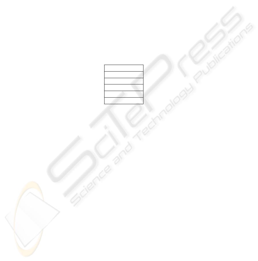
4.1 Layered Model
Application Layer
Transport Layer
Buffering Layer
Crypto Layer
Link Layer
Physical Layer
Fig.1. WATA Protocol Layers
WATA has several layers for different parts of the protocol. In other words, there are
several layers on the system, and each of them has its own duties throughout the WATA
protocol. Each layer interacts only with two other layers: the one above it and the one
below it. The layered architecture is similar to the architecture in Serial ATA, but with
more layers as in Fig. 1.
1. Physical Layer: WATA does not specify the wireless physical layer (air interface)
to be used to transport the data. Hence, it is possible to use any type of wireless
physical layer to use WATA as long as a Link Layer using this physical layer is
developed. For example, it is possible to use Bluetooth if there is a Link Layer
implementation that converts WATA packets to Bluetooth packets and vice versa.
2. Link Layer: Link Layer is responsible of being a bridge between the wireless
physical layer and upper layers. WATA does not know which physical layer is used
to transport the data at all. Therefore, its data and packets is prepared to be wireless
physical layer independent. These packets are converted to real wireless physical
connection packets in Link Layer. Moreover, if the underlying physical layer does
not provide a reliable connection, Link Layer is responsible for the reliability. That
is, it has to handle error detection, correction, fragmentation, and retransmission if
the wireless physical connections do not have such features.
54

3. Crypto Layer: It is obvious that wireless connections are insecure due to the char-
acteristics of wireless medium. Secondly, any user can access to a wireless device
that is within the range of that user. Therefore, we designed an encryption and de-
cryption mechanism to overcome both of these problems. We give details of the
layer that incorporates these mechanisms in section 4.3.
4. Buffering Layer: Wireless connections are both slower and more instable than
wired connections. Therefore, we designed a subsystem to overcome the adverse
effects of these disadvantages as much as possible. It is similar to journaling tech-
nology [8] used in some file systems. We give details of this layer in section 4.2.
5. Transport Layer: The data cannot be sent through the network without a header,
as it does not mean anything to the receivers. Hence, this layer makes the conver-
sion between real data and the WATA protocol packets that will flow through the
network. WATA packets include some headers to describe the data to be sent. We
give details of WATA protocol packets in sections 4.5 and 4.6.
6. Application Layer: This layer is where the applications using WATA are imple-
mented. Actually, file system device drivers or caching mechanisms of operating
systems run on this layer, since they are the only applications that can use WATA
protocol directly. They provide file systems to users by accessing disks through
WATA.
4.2 Buffering and Journaling
As stated in section 4.1, WATA provides a buffering mechanism to hide the stability
and performance problems of wireless connections from the user. The mechanism is
somewhat similar to the journaling feature used in advanced file systems such as NTFS
[9] and ReiserFS [10].
Incoming requests from the upper layers can basically be divided into two: reading
and writing. The approaches we have used for these two request categories are different.
Read requests must be handled in one of two ways. If the requested blocks are
already stored in the buffer, they can be immediately given to the upper layer. However,
if not, there is no other way than going to the real device, reading the blocks, and then
giving them to the upper layer. Therefore, read requests are more dependent to the
connection and thus require a more stable connection. However, buffering mechanism
in WATA implements the Least Recently Used [11] algorithm and thus tries to make as
few requests to the real device as possible.
On the other hand, write requests must not be sent to the real device immediately.
They can be stored in the local buffer and wait there for a while. Actually, Linux oper-
ating system uses floppy disks in a similar manner. One can write to a floppy on Linux
and see that the floppy drive light does not turn on until you unmount the floppy device.
To implement this, WATA uses a queue for write requests. When a write request comes
to the system, it stores the request in the buffer queue. Then the system tries to write
the accumulated requests to the real device whenever possible. This design also allows
better usage of the wireless connection, as for example the read requests, which require
immediate action, can be performed before actual writing.
55

4.3 Security and Authentication
Wireless connections are insecure due to their characteristics of the wireless medium.
The carrying medium, which is the air, allows everyone to listen to the data flowing
through it. Therefore, data transferred in plain text is readable by everyone. There are
some already implemented wireless encryption mechanisms, but we need a design be-
yond them. That is, besides using current wireless encryption mechanisms to increase
the security on wireless connections, we need the data stored in WATA devices to be
encrypted as well.
We need to store the data in a WATA device in an encrypted form, because the
WATA storage devices are not physically secured unlike current ATA or SCSI devices.
A mobile phone is an example to a WATA storage device and it is obvious that it can
easily be used by someone else other than its owner. Therefore, we also designed a
security subsystem as part of the WATA architecture.
WATA uses AES-256-CTR [12] [13] encryption algorithm. That is, it encrypts block
numbers using AES-256 and then XORs them with the data. 256-bit key of AES-256
encryption is generated by using SHA-256 [14] algorithm on a user-entered password.
Keeping the password used as input to SHA-256 secure is the responsibility of the user.
Moreover, the password used to generate the key and the key used to encrypt the
block numbers are never transmitted through the wireless connection. All encryption
and decryption are done locally on the host and the device used as storage does not
know the password or the key at all.
There is no need for an extra authentication mechanism in WATA protocol. First of
all, reading from a WATA device requires the password, as the host cannot decrypt the
data without having the password. On the other hand, writing does not require having
the password, since a user can create a new key using a different password and format
the device. It seems that there is a need for an authentication mechanism for such a case.
However, if someone else has the device on his hands, he can physically erase the data.
So, our aim is to protect the content, not the device. Therefore, we did not design an
extra authentication mechanism.
4.4 Master and Slave Devices
In current ATA systems, there are generally two channels on the board and each channel
can be used to connect two ATA devices. If two devices are connected to a channel, one
of them is the master device and the other one is the slave device. Although most users
think that slave device depends on master device for its operation, it is certainly not.
These names are just to identify devices on the same channel. When a request comes
from the channel, the device just compares its name to the name on the request and acts
accordingly.
On the other hand, WATA design includes an actual master/slave relationship be-
tween devices. One of the characteristics of wireless connections is the range. A wire-
less connection cannot transport data to a farther location than it is able to. It is actually
similar to wired connections. For example, a wired connection cannot transport data to
15m if the wire is 10m long.
56
In WATA protocol, the devices that are within the range of the host are master
devices. They can communicate with the host directly, in other words, without the need
for another device. Moreover, unlike ATA, number of master devices are not limited
within the design of WATA. On the other hand, there obviously will be a limit because
of the operating system, wireless connection medium, etc.
A WATA device, which is not within the range of the host, but is within the range
of a master WATA device can connect to the host as a slave device. However, there
are some limitations of this design. First of all, the system does not allow third level
devices. That is, a device cannot connect to the host through a slave device. It must
connect through a master device. Therefore, there are not slaves of slaves. Besides this
limitation, the system also does not allow more than one slave device to connect to the
host through the same master device. All these limitations are because of the problems
in disconnection handling. When a master device disconnects from the host, a slave
device dependent to this master device will also be disconnected. Therefore, more slave
devices will cause more instability problems.
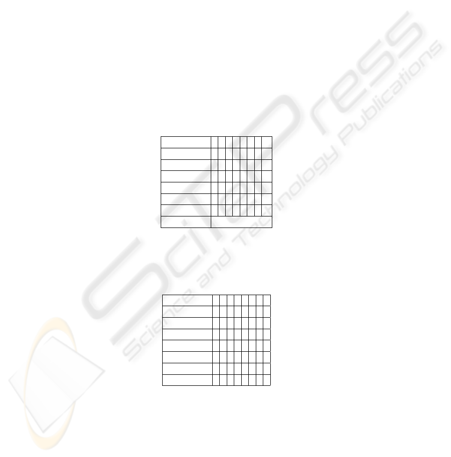
4.5 Packet Structure
Field 7 6 5 4 3 2 1 0
Features
Sector Count
LBA Low
LBA Mid
LBA High
Device
Command Command Code
Fig.2. Request Packet
Field 7 6 5 4 3 2 1 0
Error
Sector Count
LBA Low
LBA Mid
LBA High
Device
Status
Fig.3. Reply Packet
WATA packet structure looks like ATA register set. Each request and reply packet
is 56 bits in total. Only the reading reply and writing request packets will be followed
57

by data streams, whose size will be given in the packet. You can see the structure of
request packet in Fig. 2 and the structure of reply packet in Fig. 3.
Descriptions of fields in request and reply packets are:
1. Features: Parameters for the command
2. Sector Count: Number of sectors that will be used
3. LBA: Logical Block Address of the starting sector that will be used
4. Device: Device selection and additional bits for LBA
5. Command: Command code
6. Error: Bits indicating different errors
7. Status: Bits indicating status of the action
Features, Error, and Status fields can be different for each command or not applica-
ble for some commands. Device field includes 4 additional bits for LBA field. There-
fore, LBA fields are 28 bits in total. Device field includes a bit for master/slave device
selection. Remaining bits are reserved for future use. Command codes are given for
each command in section 4.6.
Sector Count field is the number of sectors that will be used in this command. For
example, a read request must include the number of sectors that should be read in this
field. The reply packet will be followed by a data stream composed of (Sector Count *
512) bytes.
4.6 Command Set
The command set is constructed with the help of ATAPI specification. ATAPI specifica-
tion includes mandatory command set for devices. The command set in WATA actually
is a small subset of this command set and includes only the basic required functions for
WATA protocol.
Control Commands:
FLUSH-CACHE: This command is used to force the device to flush its cache. If there
is any data that needs to be written physically, the device should perform the writing of
the data. This cache is nothing to do with the buffering mechanism of WATA protocol.
The cache is device specific and thus any device that do not have an inner cache must
reply to this command by saying that it is successfully completed.
IDENTIFY-DEVICE: This command is used to gather information from the device.
Features field in the request packet is used to specify the type of information requested.
If the information cannot be returned within the Status field of reply packet, a string for
example, a data stream should be returned after the packet and the size of the data must
be given in the Sector Count field of the reply packet.
SET-FEATURES: This command is used to modify device parameters. Features field
in the request packet is used to specify the parameter that will be modified. Similarly,
Sector Count and LBA fields are used to specify the value of that parameter.
58

Data Commands:
READ-SECTORS: This command is used to read one or more sectors from the device.
After the reply packet, the device must send the data sector by sector as a stream. Size
of the data stream can be calculated from the Sector Count field.
WRITE-SECTORS: This command is used to write one or more sectors to the device.
After the request packet, the host must send the data sector by sector as a stream. Size
of the data stream can be calculated from the Sector Count field.
5 Disk Emulation
One of the most important features that WATA protocol provides is usage of virtual
disks. There are many mobile devices such as mobile phones and PDAs that can be
used as storage devices. WATA Disk Emulation feature allows the users to use their
mobile devices as WATA storage disks.
Any device that has a file system, the ability to create a local file on its file sys-
tem, and provides a way of developing third-party applications involving wireless com-
munication can implement WATA Disk Emulation interface. Examples to such mobile
devices are almost all PDAs that have wireless connection capabilities and advanced
mobile phones that have wireless connection capabilities and are able to run J2ME ap-
plications.
A device that implements WATA Disk Emulation interface must create a local file
on its storage subsystem. This local file will be mapped to a disk. That is, all reading
and writing requests coming to the disk will be executed on that file. So, the device must
handle incoming WATA requests and executes the necessary operations on the file.
6 Implementation and Performance
We first implemented a Windows kernel-mode device driver to identify disk access pat-
terns of a standard user and used standard office and commonly used applications to
generate random patterns. Unfortunately, we saw that disk access patterns of differ-
ent file systems are mostly different. Furthermore, patterns are different under different
working conditions even with only one file system. One example to such conditions is
multitasking. Under heavy multitasking, it is very hard to predict the operating system’s
behavior to access to the disk. Moreover, disk fragmentation also affects the disk ac-
cess, because reading a contiguous file does not mean reading consecutive disk blocks
under fragmentation. Finally, we decided that it is not feasible to implement a pre-fetch
algorithm that uses the idle connection to retrieve disk blocks that may be used next.
The prototype implementation consists of three different parts: device driver, con-
troller, and disk emulator. As described in section 3, the controller is an application
software that runs in user-mode and is responsible for most of the WATA functionality.
We will implement the disk emulator on Windows Mobile environment to be able to
use PDAs and mobile phones as WATA disks. Therefore, we do not need any type of
new hardware to implement the prototype system.
59

Performance is mostly dependent to the physical medium as expected. It is impos-
sible to retrieve disk blocks faster than the physical medium allows. However, by using
buffering techniques, the actual user experience will be close to a regular disk drive
usage when using a standard office application that does not require heavy disk read
access.
7 Conclusion
In this paper, we describe a new wireless storage access architecture and protocol for
wireless devices. The proposal takes the inherent problems of wireless connections into
account. Furthermore, we designed the proposed system so that it does not require a
specific wireless air interface. Moreover, it is as portable as possible so that it can be
implemented on almost all operating systems. Finally, the system also supports encryp-
tion to provide security of data stored in WATA devices.
References
1. Technical Committee T13: AT Attachment - 7 with Packet Interface, Volume 1 Revision 4b.
http://www.t13.org/ (2004).
2. Serial ATA Working Group: Serial ATA: High Speed Serialized AT Attachment, Revision
1.0a. http://www.serialata.org/ (2003).
3. Technical Committee T10: SCSI Architecture Model - 3 (SAM-3), Revision 13.
http://www.t10.org/ (2004).
4. Bluetooth Special Interest Group: Specification of the Bluetooth System, Volume 1 Version
1.1. http://www.bluetooth.com/ (2001).
5. IP Storage Working Group: Internet Small Computer Systems Interface (iSCSI) (RFC 3720).
http://www.ietf.org/html.charters/ips-charter.html (2003).
6. Khoo, P. B. T., Wang, W. Y. H.: Introducing A Flexible Data Transport Protocol for Network
Storage Applications. 10th NASA Mass Storage Systems and Technologies Conference / 19th
IEEE Symposium on Mass Storage Systems (2002).
7. Machek, P.: Network Block Device. http://nbd.sourceforget.net/ (1997).
8. Hagmann, R.: Reimplementing the Cedar File System Using Logging and Group Commit.
11th ACM Symposium on Operating Systems Principles (1987).
9. Microsoft Corporation: Microsoft Windows NT from a Unix Point of View. Business Systems
Technology Series (1995).
10. The Naming System Venture: ReiserFS. http://www.namesys.com/ (1998).
11. Tanenbaum, A. S.: Modern Operating Systems, Second Edition. Prentice Hall, Inc. New
Jersey (2001).
12. U.S. National Institute of Standards and Technology: Specification for the Advanced En-
cryption Standard (AES). NIST Federal Information Processing Standards Publication 197
(2001).
13. U.S. National Institute of Standards and Technology: Recommendation for Block Cipher
Modes of Operation. NIST Special Publication 800-38A (2001).
14. U.S. National Institute of Standards and Technology: Specifications for the Secure Hash
Standard. NIST Federal Information Processing Standards Publication 180-2 (2002).
60
