
An Integration Scheme for CPN and Process Algebra
Applied to a Manufacturing Industry Case
Manuel I. Capel, Juan A. Holgado, Agustín Escámez
Department of Software Engineering. University of Granada, Granada (Spain)
Abstract. A semiformal development method for obtaining a correct design of
embedded control and real-time systems is presented. The design is obtained
from a Colored Petri Net (CPN) model of a real-time system, which is
subsequently transformed into a formal system specification using CSP+T
process algebra. The method translates CPN modelling entities into abstract
processes, which allow the expression of concurrency and real-time constraints.
The correct design of a “key“ component (feed belt controller) of a
paradigmatic manufacturing problem (the Production Cell) is discussed as to
show the applicability of our method.
1 Introduction
We present here an approach for modeling and validating embedded control and real-
time systems (ECRTS) at the design stage of the software development cycle. Our
aim is to perform the validation of timing constraints by formal tools based on a timed
Process Algebra, instead of having to wait for the target system to be coded.
Currently, the timing and dependability requirement analysis of ECRTS is carried
out after completely developing a system prototype. The prototype is usually
discarded, particularly first prototypes, and a revision of system specification and
detailed design phases of the life cycle result, therefore the development cost
increases and the delivery date of the final system becomes delayed.
There is nowadays a significant research aimed at using Colored Petri Nets (CPN)
[1] for modeling the behavior of discrete reactive systems, to which ECRTS belong.
In this respect, it is worth mentioning, among many of the current proposals, the work
presented in [2] to model the dynamic of message passing between software
components in a distributed manufacturing system, or the one discussed in [3] to
provide systematic guidelines for using Colored Timed Petri Nets (CTPN) as a
modeling language for soft real-time systems. Another interesting proposal for using
CPN segments to model the dynamic behavior of concurrent software architectures
can be found in [4]. The application of CPN and CTPN has been mainly aimed at
modeling dynamic, discrete event driven systems, possessing soft timing constraints.
On the other part, there are many proposals to obtain a formal specification of ECRTS
by using process algebras [5-7]. In regarding formal specification and probably
correct development of reactive systems, some of the currently most significant work
has been carried out by the authors of [8], who propose to generate a formal
specification from an UML model of the system under development, complemented
I. Capel M., A. Holgado J. and Escámez A. (2005).
An Integration Scheme for CPN and Process Algebra Applied to a Manufacturing Industry Case.
In Proceedings of the 3rd International Workshop on Modelling, Simulation, Verification and Validation of Enterprise Information Systems, pages 39-48
DOI: 10.5220/0002566600390048
Copyright
c
SciTePress

with trace assertions in a CSP-like notation called CSP
jassda
[9]. Differently and yet
complementing the above described methods, we propose a systematic development
method aimed to set the stage for generation of first correct prototypes of ECRTS
from an initial CPN model. By using a CPN model, a description of the system
dynamic behavior can be obtained from an architectural point of view. The model is
subsequently transformed into a detailed system design by using the CSP+T process
algebra notation and coded using the Java programming language. CSP+T process
terms are used here to model real-time processes including the specification of their
timing requirements in order to carry out a further validation by deploying different
industry oriented tools, e.g., 20-SIM [10]; THESIS [11], or FDR [12]. These tools
may complementarily be used to check different sort of properties and to simulate the
execution of the target system as well.
The remainder of the paper is structured as follows. We first give some background
on CPN modeling and CSP+T process algebra, which are necessary to understand the
formal notations on which the system development technique is based. Then, the
proposed method is applied to solve a design problem of an industry case study, the
production cell‘s feed belt control component. The case study shows how the
proposed method can be applied to derive a manufacturing industry system, which
also contains real-time timing constraints. Finally, the conclusions and the ongoing
lines of work are presented.
2 Modelling Methods
2.1 System Specification with CPN
A CPN allows us to describe complex systems by compact and executable models; an
example of a CPN model chart can be seen in figure 4. The states of the system are
modeled by places, which are drawn as circles or ellipses. The actions of a CPN
model are represented by means of transitions, which are drawn as rectangles. A
marking is understood as a state of the model CPN and consists of a distribution of
tokens on the places. There is a distinguished marking, called the initial marking,
which is used to describe the initial state of the system. The initial marking of any
place is written on the upper right or left corner of the place. Compared to Petri Nets
(PN), the CPN formalism provides the possibility of having different types of tokens
associated to the places of the net. Each one of the colored tokens can transport
information whose type and purpose is interpreted depending on the transitions that
occur at a given instant of the CPN model execution. The model execution consists of
a series of occurrences of enabled transitions. The occurrence of the transition t
removes tokens from the input places (which are given by the input function I(t)), and
adds tokens to the output places (which are given by the input function O(t)), thereby
changing the state (the marking) of the CNP model. The number of tokens of each
type added or removed is given by the evaluation of arc expressions, which are
Standard ML (SML) expressions. An assignment of data values to the free variables
occurring in the arc expressions is called a binding. Transitions may occur in different
modes depending on the possible bindings affecting the expressions associated to
their surrounding arcs. There is also the possibility to attach a predicate, called a
40
guard, which is written within square brackets in the chart, to each transition, so that
only bindings that evaluate the guard to true are accepted when the transition occurs.
It can be proved that a CPN model with color domains of finite cardinality has the
same descriptive power for modeling information systems as the PN formalism, since
it is always possible to build an equivalent PN model of a given CPN by using the
“unfolding algorithm”. Nevertheless, PN models are usually (except for systems with
very few states) huge and difficult to understand and simulate compared with the CPN
ones. The improved compactness and readability of CPN w.r.t. PN is not the only
amendment, but they also have the capability of parameterization of the constructed
models that results quite convenient in the design and analysis stages of software
systems development.
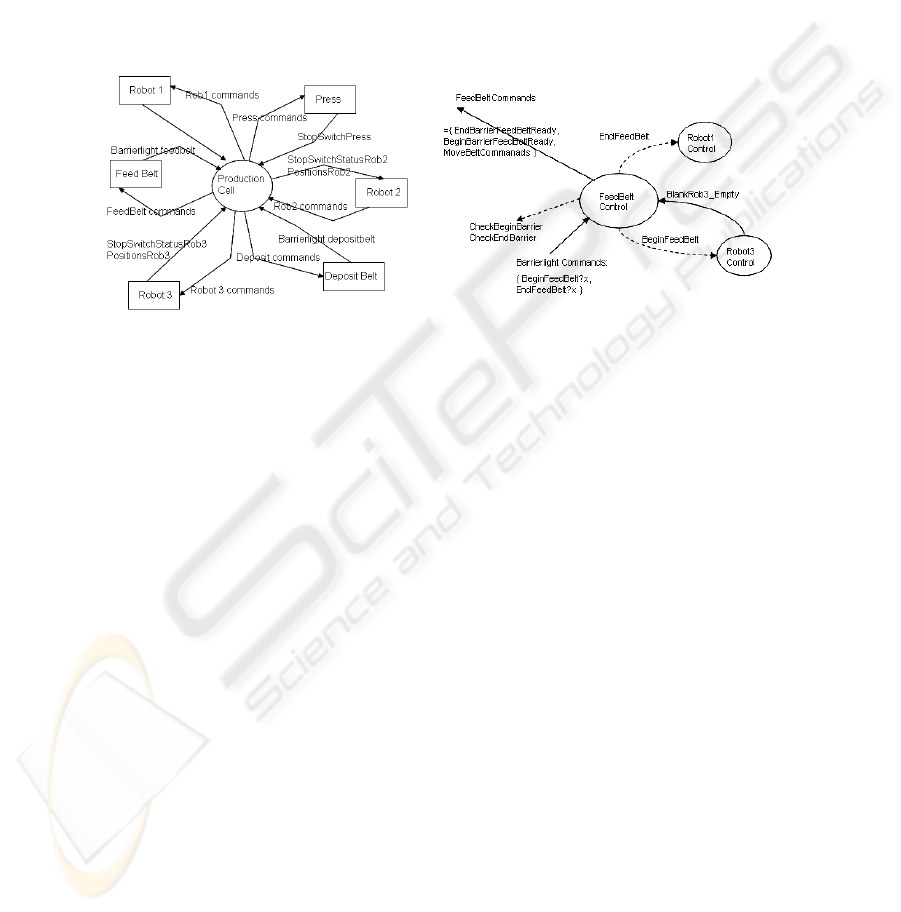
Fig. 1. Production Cell context diagram
2.2 Drawbacks of CPN as a Specification Notation for Real-time Systems
CPN and CTPN lack of specific constructs to fully describe the behavior of hard real-
time systems. Our approach is, by adapting some of its undoubtedly useful modeling
elements, to use these standard notations mainly to specify the behavioral parts of the
system and, by using another compatible format notation, to provide additional
specification of real-time properties that might not be directly addressed by the CPN
model. In this respect, it can be shown that CSP+T process algebra formalizes the
semantics of a substantial subset of CPN by using a set of rules similar to the one
defined in [6].
2.3 Real-Time System Specification with CSP+T
The group of CSP derivatives to describe time intervals includes Timed CSP [7] and
CSP+T [5], the latter being a simpler approach. Providing less descriptive power,
although still powerful enough to formally describe a set of primitive processes with
time constrained behavior, CSP+T is an adequate formal specification language for
the majority of real-time systems.
The syntax of CSP+T, adapted to our method, which is detailed in [6]:
Every process P defines its own set of communication symbols, named
communication alphabet
α
(P).
41

The communication interface comm_act(P) of a given process P contains all the
CSP-like communications ({?, !}) in which P can engage and the alphabet
α
(P).
An operator,
Ë
(star) denotes process instantiation. Given P', the timed version of
P, which is instantiated at time 1, the specification of P' becomes
P'= 1.
Ë→
s.a
→
STOP, where s
∈
[1,
∞
)
An event operator >< to be used jointly with a variable to record the time instant at
which the event occurs, ev
><
v means that the time at which ev is observed is in v.
P= 1.
Ë→
a
><
var
→
STOP
for each process execution, the time at which a occurred will always be var
≥
1.
Each event is associated with a time interval, called the event-enabling interval.
P= 0.
Ë→
[1,2] a
><
v
→
STOP
The value of the marker variable v will satisfy the inequality 1
≤
v
≤
2.
If the preceding event occurs at time t
0
, then rel(x, v)= [x+v-t
0
, v-t
0
], since the
times for events are absolute and for intervals are relative to the preceding event.
P = ... E.P’ . E = {s | s = rel(x, v)}
2.4 Generation of a System Specification from CPN
To derive a detailed system specification in CSP+T from a CPN one, we will adopt a
bottom-up process that consists of the following steps:
1. Identify the main actions that cause a change in the control state of the system, then
define what are the multistates in which the system enters during its execution, as
well as their synchronization restrictions and time constraints.
2. Start by representing the reactive behavior of the lower level subsystems of the
system under development as CPN models. Lower level actions, which are related
between them and modify the state of the controller and/or its environment, must
be grouped within transition instances, according to the CPN formal notation. For
instance, several atomic actions the controller performs can be defined as edges
outing the same transition towards distinct places or the same places but carrying
tokens of different color. Modifications of relevant condition values to the state of
the controller can be modeled by assigning predicates to transitions or by modeling
elaborate data types associated to the color domain of places and transitions in the
CPN.
3. Add simulated blocks to represent external devices or continuous components.
4. Break down each CPN previously built into CSP+T syntactic terms. Each
transition on the CPN can provide several atomic actions and/or communications
when it is translated into process terms. As a general rule, safe subnets of a CPN
should be represented as a single CSP+T process, being their places translated into
named terms according to the CSP+T syntax rules. The subprocesses should be
compounded by the parallel CSP operator. The change of value of predicates, the
modifications of the number or type of tokens situated in a given place are modeled
by CSP communications.
5. Once a CSP+T model has been obtained for every CPN model in which the target
system specification was initially structured, a unique CSP+T process will be
defined to model the complete system. If an scheme has to be included into one of
a higher level, then logically connected subprocess terms must be gathered into
42
more abstract ones by using the hiding and parallel operators, thus progressively
integrating the CSP+T model of the system in an ascending way.
6. The iterative process finishes when a unique process whose communication
interface satisfies the initial abstract specification, e.g., which was usually
described at the requirements specification stage by the user, and informally
defined by a System Context Diagram or an English specification document.
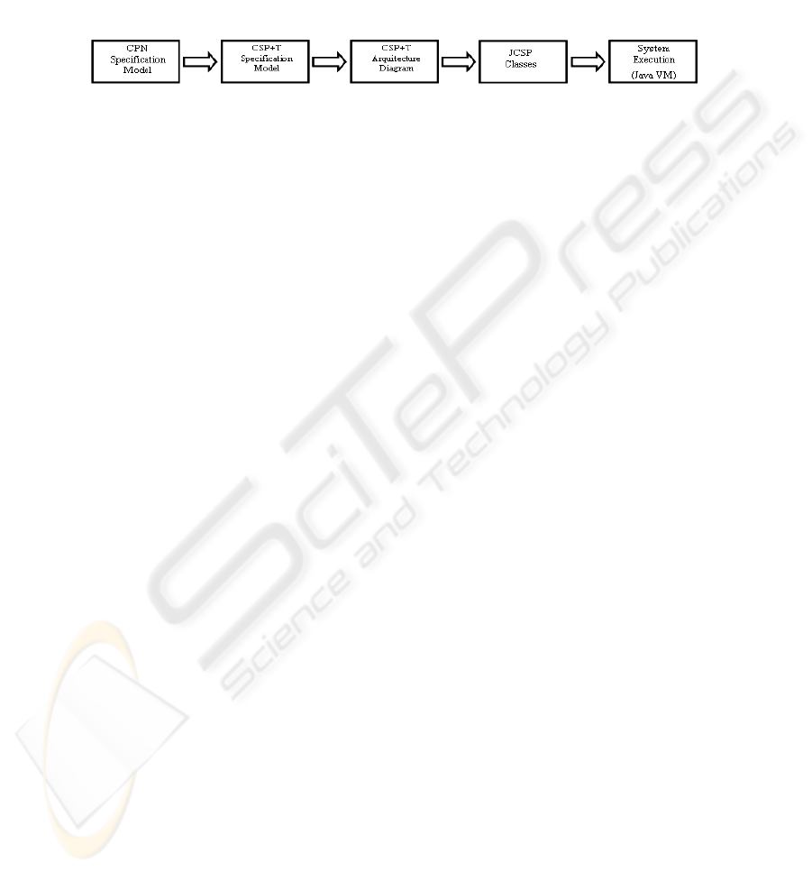
Fig. 2. Development levels
To carry out an execution of a complete specification in CSP+T of the target system
by a simulation tool, additional blocks must be added to the final model. These blocks
represent the external entities of the system and must be modeled according to the
specific physical devices (actuator or sensor) that supply signals (data or event)
to/from the system.
3 Production Cell Feed Belt Control Subsystem: a Case Study
The production cell is a well-known realistic manufacturing industry oriented
problem [13], where safety requirements regarding the fulfillment of timing-
constraints by the different concurrent movements of the cell components (robot
arms, conveyor belts, press, etc.) are of paramount importance in order to have a
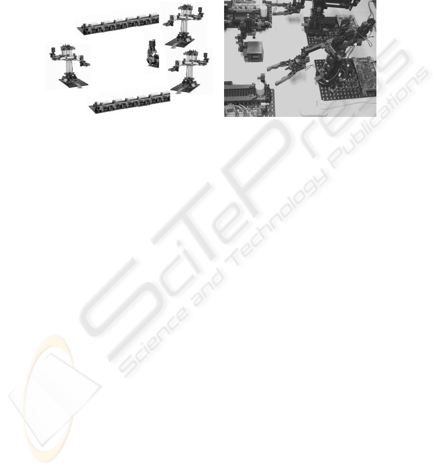
useful design of the target system. The proposed configuration of the production cell
is a closed loop feedback control system composed of three robot arms, two conveyor
belts and a press (figure 3 (a)); the blanks are circularly conveyed through both belts
by following a continuous loop, so that the system can indefinitely function without
intervention of the operator. The step-by-step system functioning is as follows: after a
metal blank is placed on the feed belt, it is moved towards the other end of the belt,
the first robot arm takes the blank when it reaches the end and places it on the press,
the press forges the metal blank (actually, the press simulates this action) and opens
again, forged metal plates are taken out of the press and put on a deposit belt by a
second robot arm, and, finally, a third robot arm picks the blank up and puts it again
on the feed belt to close the circular path that the blanks follow. A physical simulation
of the proposed system was performed using a scaled-down industry model built from
“construction kits” of Fischertechnik© (figure 3 (b)). This allows us to have a fully
functional model that mimics the operations of the system.
In this paper only a description of the detailed specification, design and
implementation of the subsystem feed belt control of the production cell is presented,
since the design of the entire system is too big to be discussed in a comprehensible
way within the pages of a paper. To carry out the movement of objects from one place
of the industrial plant that holds the production cell to another one, the feed belt
device contains two sensors and one actuator. The actuator is a DC motor that moves
the conveyor belt towards a pre-selected direction, i.e., to the right if the deposit belt
43
moves, or to the left if the feed belt does so. The two sensors are lightbarriers or
photosensors placed at the beginning (L1) and at the end (L2) of the conveyor belt.
The actuator and sensors of the feed belt device are driven by an embedded
microcontroller, which sends the states of the sensors and receives software
commands from the main system through a serial communication line.
Robot 1
Robot 2
Robot 3
Deposit Belt
Feed Belt
Press
Fig. 3. The Production Cell: (a) proposed configuration, (b) view of the physic model
3.1 System Specification as a CPN Model
To formally specify the Feed Belt Control (FBC), a CPN model according to our
methodology is shown below. The objective of this control process is to ensure that
the feed belt can reach safety positions for blanks regarding the concurrent
movements of the robot arms, which could collide with the conveyed blanks on the
belts if no control of their movements is defined, i.e., one blank cannot be moved until
the robot retracts the arm after having dropped it on the belt. Obviously, process
design must guarantee that the behavior of an implemented process satisfies the
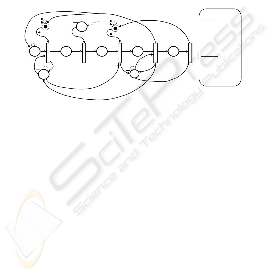
specification of the production cell. The CPN describing the time-dependent
behaviour of the belt control can be seen in figure 4. The sequence of states and
transition between states represented by the CPN are summarized as follows:
− the initial marking represents the starting state of the different devices to which the
feed belt has to interact during FBC process execution, sensors (places L1, L2) and
actuators (motor commands yielded by firing T3 and T4) are tested while the
control is in this state;
− the belt control waits in place A for the arrival of a blank, which is dropped on one
of its two ends by the robot 3 arm;
− robot 3 arm drops the object on the belt (T2) and pulls back its arm in a safe way
(while the model control is marking place C);
− the motor starts moving the object towards the lightbarrier L2 (T3);
− once the blank reaches L2, the feed belt motor is commanded to stop (T4);
− the controller waits for robot 1 picks up the blank (while the model control is
marking place E);
− finally, the control returns to its initial state (T5).
A specification of the Feed Belt Control in terms of CSP+T is next obtained by
applying a similar set of rules presented as the one in [6]. One CSP+T syntactic term
44
must be specified for each place and its outing transition in figure 4. In the
WaitingBlank specification, the “Begin_Feed_Belt _Full_true >< tBeginFeedBelt”
CSP+T construct is used to represent a transition going to the next state, which
includes the activation condition Begin_Feed_Belt_Full_true, known as marker event,
and the variable tBeginFeedBelt used to record the time instant at which the marked
event occurs. Regarding the specification of enabling intervals, the enabling interval
I(DtakingoutRob3, t_beginfeed) on the output transition of the TakingOut state
represents the delay interval, named DTO in figure 4, needed to pull back the robot 3
arm before the motor starts moving the blank towards the end of the belt.
Fig. 4. Feed Belt Control CPN Specification.
3.2 System Specification in CSP+T
The processes BeginContinuousProcess and EndContinuousProcess that appears
included in the specification are extra intermediate processes introduced to model in
CSP+T the continuous flows BeginBarrierFeedBelt and EndBarrierFeedBelt.
Feed_Belt_Movement = start_time.→start; InitFeedBelt
InitFeedBelt= EndBarrierFeedBelt_Ready !false
→BeginBarrierFeedBelt_Ready!true → Waiting_Blank
Waiting_Blank = (CheckBeginBarrier → BeginFeedBelt ? x
→if(x=BeginFeedBelt_Full) then BeginFeedBelt_Full_true;
Waiting_Blank
| BeginFeedBelt_Full_true ><t_BeginFeedBelt;
BeginFeedBelt →BeginFeedBelt_Time!t_BeginFeedBelt;
WaitingBlank?resume())
TakingOut_Rob3=BlankRob3_Empty →
BeginFeedBelt_Time? t_BeginFeedBelt → I(DtakingOutRob3,
t_BeginFeedBelt); EndBarrierFeedBelt_Ready!true →
BeginBarrierFeedBelt_Ready!false→
→Sync?EndFeedBeltCleraded();MoveBelt!left;
MovingFeedBelt)
MovingFeedBelt= (CheckEndBarrier → EndFeedBelt ? x
→ if(x=EndFeedBelt_Full) then EndFeedBelt_Full_true end;
MovingFeedBelt
2
T
x
R
bf
0’e
x
(If blanks follows a circular path)
1’e
1
A
B
C
DE
R
3
T
1
2
T
3
T
4
x
x
x
t
t
x
x
x
bf
x
L
1
1’e
1’e
[
x
=
bf
]
now
[
-
t > DTO ]
ef
[
x
=
]
]
ee
[
x
=
1’e
x
true
false
0’e
0’e
BC
:
R
esume
()
Æ
R
BeginFeedBelt_Full
Æ
bf
EndFeedBelt_Cleared
Æ
BC
Æ
bf
ef
Æ
ee
DTakingOut
Æ
DTO
:
C
olor E
=
with
e
C
olor U
=
with
bf
|
ef
|
ee
C
olor B
=
with
true
|
false
Color T = real
Var
x : U
Var
t : T
0
1
1
1’e
1’e
1
T
5
EndFeedBelt_Empty
EndFeedBelt_Full
BeginFeedBelt_Full
Notation
Definitions
true
L
0’e
0’e
45

| EndFeedBelt_Full_true → MoveBelt!stop;
BeginBarrierFeedBelt_Ready!true → TakingOut_Rob3)
Unloading_Blank= (CheckEndBarrier → EndFeedBelt ? x →
if (x=EndFeedBelt_Empty) then EndFeedBelt_Full_false;
Unloading_Blank
| EndFeedBelt_Full_false → EndBarrierFeedBelt_Ready !false →
EndFeedBelt; WaitingBlank!resume();
Sync!EndFeedBeltCleraded();UnloadingBlank)
The Feed Belt Control (FBC) must be obtained by the parallel composition of its
component subprocesses without any additional re-structuring of the specification. All
the internal events must be hidden using the hiding operator \, so that the
communication interface of FBC coincides with the flows in figure 1 (b). The FBC
process is modelled by:
FBC = Feed_Belt_Movement\{start}||InitFeedBelt||WaitingBlank\
{BeginFeedBelt_Full_True, BeginFeedBelt_Time}||
TakingOut_Rob3\{BeginFeedBelttime}||
Moving_Feed_Belt\{EndFeedBelt_Full_true }||
Unloading_Blank\{EnFeedBelt_Full_false,
Waiting_blank!resume(), WaitingBalnk?resume(),
Sync!EndFeedBeltCleraded(),Sync?EndFeedBeltCleraded()}
so the communication interface of the FBC is:
Interface (FBC) = {EndBarrierFeedBeltReady!false,
BeginBarrierFeedBelt_Ready!true,
BeginBarrierFeedBelt_Ready!false, CheckBeginBarrier,
CheckEndBarrier, BeginFeedBelt?x,BeginFeedBelt,
BlankRob3?empty, EndFeedBelt?x, MoveBelt!stop,
EndFeedBelt,}
3.3 CSP Process Architecture Diagram
In order to obtain an executable implementation of the CSP+T terms specification we
use the library of Java classes JCSP[14], which is a correct implementation of the
CSP distributed parallel programming model [7]. The complexity of the specification
of a set of concurrent communicating processes can be handled by using the JCSP
library, which implements the CSP programming primitives at the level of
applications programmed in the Java programming language.
Each JCSP process is encapsulated in an independent active class derived from
CSProcess Java interface that overrides the functionality of the method run() and
defines, as the parameters of the constructor method, input and output channels used
by the process to communicate with other processes. In order to facilitate the
modeling of the JCSP processes from a given system specification in terms of
CSP+T, a software graphical tool has been implemented in pure Java, so that the
translation of CSP+T processes, mainly when there are multiple levels of nested
processes, becomes easier and less error prone. With this application, we begin
modeling in a graphical way the high layer of CSP+T processes that represents the
production cell and the processes necessary for handling the communications with
each interacting device; the model obtained after the accomplishment of this action
corresponds to the stage given by the initial system context diagram (SCD) shown in
figure1, but it gives a more complete and precise information, including an
46
architectural view, of the system. Then, the channels that constitute the
communication interface of a process can be defined and connected with other
processes to obtain a net of processes. Once all the processes are designed, according
to the previous system specification in CSP+T, the behavior of each process is
implemented directly in Java. An execution of the built model of the entire system can
be performed within the framework of the proposed software tool, or the code
generated by compiling the classes that represents the JCSP processes of the system
can be downloaded and run into an embedded microcontroller.
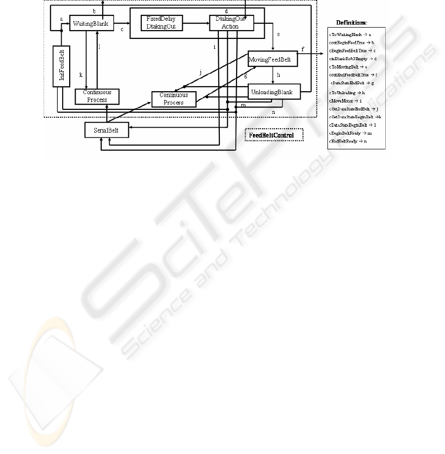
Fig. 5. CSP+T Architecture Diagram of the Feed Belt Control Process
To implement the Feed Belt Control Subsystem of the production cell and,
therefore, to execute it, other processes apart from the FBC process must be designed.
We need to specify additional processes, as these to drive the communication to each
external device (which appear as terminators in the SCD), or intermediate CSP+T
processes to represent necessary control interactions not included yet. A reduced
implementation of the Feed Belt Control Subsystem is carried out by only adding a
SerialBelt process to hide the serial communication to the controller that handles the
actuators and sensors of the device as can be seen in figure 5. Therefore, the design of
the CSP+T architecture obtained with the proposed software tool must be seen as a
more abstract, configurationally oriented, structure of the CSP+T processes or JCSP
processes that constitute the system under development.
4 Conclusions and Future Work
We have presented a development method for obtaining a correct design of embedded
control and real-time systems (ECRTS) from a high level CPN model aimed at
describing their dynamic behavior. The drawbacks that presents the CPN notation
when applied to real-time modeling has been overcome by transforming the initial
CPN model into an equational specification made up of syntactic terms in CSP+T
process algebra, so that hard timing constraints on the execution of a target system
under development can be reflected in this formal specification. As to show the
applicability of the method, the detailed design of a key component of a paradigmatic
47

manufacturing example has been discussed. Our future plans are twofolded, firstly,
starting from their CSP+T specification, to generate Java code for ECRTS in several
computing platforms; secondly, to automate the generation of CSP+T specifications
from CPN models.
Acknowledgement
This work is funded by the research project MAT2004-06872-C03-03.
References
1. JENSEN, K. Colored Petri Nets: Basic Concepts, Analysis Methods and Practical Use.
Monographs in Theoretical Computer Science. Springer, 1992.
2. LIN, E.Y., ZHOU, C.: Modeling and Analysis of Message Passing in Distributed
Manufacturing Systems. IEEE Transactions on Systems, Man and Cybernetics, Part C:
Applications and Reviews, 29,2, 1999, pp.250-262.
3. CHOPPY, C., PETRUCCI, L.: Towards a Methodology for Modeling with Petri Nets.
Proceedings on Practical Use of Colored Petri Nets, Aarhus, Denmark, 2004, pp.39-56.
4. PETTIT, R.G., GOMAA, H.: Validation of Dynamic Behaviour in UML Using Coloured
Petri Nets. UML 2000 Dynamic Behavior Workshop, England, 2000.
5. ŽIC, J.J.: Time-Constrained Buffer Specifications in CSP+T and Timed CSP. ACM
TOPLAS, 16, 1994, 6, pp.1661-1674.
6. CAPEL, M.I., HOLGADO, J.A.: Transforming SA/RT Graphical Specification into the
CSP+T Formalism: Obtaining a Formal Specification from Semi-formal SA/RT Essential
Models. Proceedings of ICEIS 2005 (to appear), Miami, USA, May 24-26, 2005, 8 pages.
7. HOARE, C.A.R.: Communicating Sequential Processes, Prentice-Hall, Englewood Cliffs
(N.J.), 1985
8. MOELLER, M., OLDEROG, E.R., RASCH, H., WEHRHEIM, H. Linking CSP-OZ with
UML and Java: A Case Study. In IFM’2004. LNCS 2999, Springer-Verlag, 2004, pp.267-
286.
9. MOELLER, M.: Specifying and Checking Java using CSP. In FTfJP’2002: Workshop on
Formal Techniques for Java-like Programs. Computing Science Department, U. of
Nijmegen, 2002, Technical Report NIII-R0204
10. BROENINK, J.F.: Modeling, Simulation and Analysis with 20-SIM. Journal A of the
special issue on CASD, 1997, pp.22-25.
11. WIJBRANS, K.C.J., VAN AMERONGEN, J., BAKKERS, W.P., BROENINK, J.F.:
Tweente Hierarchical Embedded Systems Implementation by Simulation (THESIS): A
Structured Approach to Controller Realisation on Transputers. Journal A, 34, 1, 1993, pp.
51-59.
12. FDR. Formal Systems (http://www.fsel.com)
13. LEWERENTZ, C., LINDNER, T: Formal Development of Reactive Systems: Case Study
Production Cell. LNCS 891, Springer-Verlag, January 1995.
14. WELCH, P.: Process Oriented Design for Java: Concurrency for All. In: Parallel and
Distributed Processing Techniques and Applications, PDPTA 2001, Las Vegas, Nevada,
USA, 2001.
48
