
AUTONOMOUS GAIT PATTERN FOR A DYNAMIC BIPED
WALKING
Christophe Sabourin, Kurosh Madani
Laboratoire Images, Signaux, et Syst
`
emes Intelligents (LISSI EA / 3956)
Universit
´
e Paris-XII, IUT de S
´
enart, Avenue Pierre Point, 77127 Lieusaint, France.
Olivier Bruneau
Laboratoire Vision et Robotique - Ecole Nationale Sup
´
erieure d’Ing
´
enieurs de Bourges
10 Boulevard Lahitolle 18020 BOURGES, France.
Keywords:
Autonomous gait pattern, biped dynamic walking, Fuzzy-CMAC neural networks.
Abstract:
In this paper, we propose an autonomous gait pattern for a dynamic biped walking. Our approach takes
simultaneously advantage from a Fuzzy-CMAC based computation of robot’s swing leg’s desired trajectory
and a high level control strategy allowing regulating the robot’s average velocity. The main interest of this
approach is to proffer to the walking robot autonomy and adaptability involving only one parameter: the
average velocity. Furthermore, this approach allows increasing the robustness of the walking robot regarding
the forwards pushed force.
1 INTRODUCTION
The design and the control of biped robots are one
of the more challenging topics in the field of robotics
and were treated by a large number of research works
over past decades. The potential applications of this
research area are very foremost in the middle and long
term. Indeed this can lead firstly to a better compre-
hension of the human locomotion mechanisms, what
can be very helpful for the design of more efficient
orthosis. Secondly, the humanoid robots are intended
to replace the human for interventions in hostile en-
vironments or to help him in the daily tasks. How-
ever, in addition to the problems related to autonomy
and decision of such humanoid robots, their basic lo-
comotion task is still today a big challenge. If it is
true that a number of already constructed prototypes,
among which the most remarkable are undoubtedly
the robots Asimo (1) and HRP-2P (2), have proved the
feasibility of such robots, it is also factual that the per-
formances of these walking machines are still far from
equalizing the human’s dynamic locomotion process.
The design of new control laws allowing real time
control for real dynamic walking in unknown envi-
ronments is thus today fundamental. Moreover, such
robots must be able to adapt themselves automatically
to indoor and outdoor human environments. Conse-
quently, it is necessary to develop more autonomous
biped robots with robust control strategies in order to
allow them, on the one hand to adapt their gait to the
real environment and on the other hand, to counteract
external perturbations.
In the field of biped locomotion, the control strate-
gies can be classified in two main categories. The
first is based on a kinematics and dynamic model-
ing of the mechanical structure. This implies to iden-
tify perfectly the intrinsic parameters of biped robot’s
mechanical structure, requires a high precision mea-
surement of the joints’ angles, velocities and accel-
erations and needs a precise evaluation of interaction
forces between feet and ground. Moreover, the con-
trol strategies based on a precise kinematics and dy-
namic modeling require a lot of computation. For all
these reasons, the computing of the on-line trajecto-
ries generally are given by using a simplified model-
ing and the stability is ensured by the control of the
Zero Moment Point (ZMP) (3) (4) (5) (6). The sec-
ond solution consists to use the soft-computing tech-
niques (fuzzy logic, neural networks, genetic algo-
rithm, etc..) and/or pragmatic rules resulting from
the expertise of the walking human. Two main ad-
vantages distinguish this second class of approaches.
Firstly, it is not necessary to know perfectly the char-
acteristics of the mechanical structure. Secondly, this
category of techniques takes advantage from learning
(off-line and/or on-line learning) capabilities. This
last point is very important because generally the
learning ability allows increasing the autonomy of the
biped robot.
In this paper, we present a control strategy for
26
Sabourin C., Madani K. and Bruneau O. (2006).
AUTONOMOUS GAIT PATTERN FOR A DYNAMIC BIPED WALKING.
In Proceedings of the Third International Conference on Informatics in Control, Automation and Robotics, pages 26-33
DOI: 10.5220/0001203000260033
Copyright
c
SciTePress
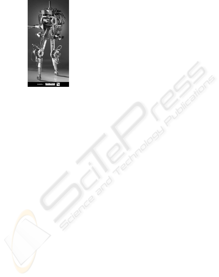
Figure 1: Prototype RABBIT.
an under-actuated robot: RABBIT (figure 1) (7) (8).
This robot constitutes the central point of a project,
within the framework of CNRS ROBEA program (9),
concerning the control of walking and running biped
robots, involving several French laboratories.
This robot is composed of two legs and a trunk and
has no foot as shown on figure 1. If it is true, from de-
sign point of view, that RABBIT is simpler compared
to a robot with feet, from the control theory point of
view, the control of this robot is a more challenging
task, particularly because, in phase of single support,
the robot is under-actuated. In fact, this kind of robots
allows studying real dynamical walking leading to the
design of new control laws in order to improve biped
robots’ current performances. It is pertinent to note
that the ZMP approach, generally used for humanoid
robots, is not appropriated for the case of a biped
without feet, because the contact surface between the
foot and the ground is limited to a point.
This project has been the subject of many publica-
tions concerning the field of control strategies emerg-
ing on the one hand from rigorous mathematical mod-
eling, and on the other hand issued from the use of
CMAC neural networks. Developed approaches have
been subject of experimental validations (10) (11).
In this paper, we present an extension of the control
strategy using the CMAC neural network. In our pre-
vious work (10), the CMAC was used to generate the
joint trajectories of the swing leg but these trajecto-
ries were fixed. Consequently, the step length could
not be changed during the walking. Today, our aim is
to develop a control strategy able to generate a fully
autonomous biped walking based on a soft-computing
approach. In this paper, we show how it is possible to
change the walking gait by using the fusion of differ-
ent trajectories learned by several CMAC neural net-
works. In fact, our control strategy is based on two
stages :
• The first one uses a set of pragmatic rules allowing
to stabilize the pitch angle of the trunk and to gen-
erate the leg motions (12). This control strategy al-
lows generating a stable dynamic walking with step
length and velocity transitions. During this first
stage, the robot is supposed to move in an ideal en-
vironment (without disturbance). We also assume
that frictions are negligible. However, in the case of
our intuitive control, it is not possible to counteract
external (pushed force) and internal (friction) dis-
turbances. Consequently, we propose to use a neu-
ral network allowing to increase the robustness of
our control strategy. In fact, in the first stage, the
pragmatic rules are used as a reference control to
learn, by a set of CMAC neural networks, a set of
joint trajectories.
• In the second stage, we use these neural networks
to generate and to modulate the trajectory of the
swing leg. This trajectory is obtained by fusing
outputs of several neural networks. In fact, the
data contained in each CMAC represent a reference
walking carried out during the first stage. The fu-
sion is realized by using fuzzy logic. Consequently,
it is possible to modulate, for example, step length
according to average velocity. Furthermore, the fu-
sion allows us to generate an infinity of trajectories
only from a limited number of walking references.
This paper is organized as follows. Section 2
presents the characteristics of our virtual under-
actuated robot. In Section 3, we explain the method
used to train each CMAC neural network. Section 4
presents the control strategy using the Fuzzy-CMAC
neural networks. In section 5, we give the main re-
sults obtained in simulation. Conclusions and further
developments are finally given.
2 VIRTUAL MODELING OF THE
ROBOT
The robot RABBIT has only four articulations: one
for each knee, one for each hip. Motions are included
in the sagittal plane by using a radial bar link fixed at
a central column that allows to guide the direction of
progression of the robot around a circle. Each artic-
ulation is actuated by one servo-motor RS420J. Four
encoders make it possible to measure the relative an-
gles between the trunk and the thigh for the hip, and
between the thigh and the shin for the knee. Another
encoder, installed on the bar link, allows to give the
pitch angle of the trunk. Two binary contact sensors
detect whether or not the leg is in contact with the
ground. Based on the informations given by encoder,
it is possible to calculate the step length L
step
when
the two legs are in contact with the ground. The dura-
AUTONOMOUS GAIT PATTERN FOR A DYNAMIC BIPED WALKING
27
tion of the step t
step
is computed by using the contact
sensor informations (duration from takeoff to landing
of the same leg). Furthermore, it is possible to esti-
mate the average velocity V
M
by using (1).
V
M
=
L
step
t
step
(1)
The characteristics (masses and lengths of the
limbs) are summarized in table 1. Since the contact
between the robot and the ground is just one point
(passive DOF), the robot is under-actuated during the
single support phase: there are only two actuators (at
the knee and at the hip of the contacting leg) to control
three parameters (vertical and horizontal position of
the platform and pitch angle). In fact, this robot rep-
resents the minimal system able to generate a biped
walking and running gaits.
Table 1: Masses and lengths of the limbs of the robot.
Limb Weight (Kg) Length (m)
Trunk 12 0.2
Thigh
6.8 0.4
Shin
3.2 0.4
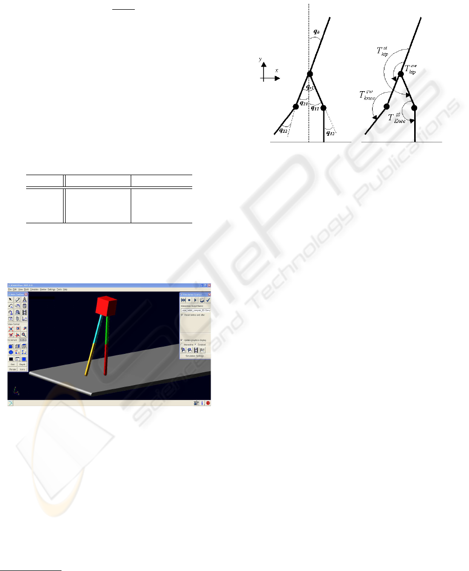
The numerical model of the robot previously de-
scribed was designed with the software ADAMS
1
(Fig. 2).
Figure 2: Modeling of the robot with ADAMS.
This software, from the modeling of the mechani-
cal system (masses and geometry of the segments) is
able to simulate the dynamic behavior of this system
and namely to calculate the absolute motions of the
platform and the relative motions of the limbs when
torques are applied on the joints by the virtual actua-
tors . Figure 3 shows references for the angles and the
torques required for the development of our control
strategy. q
i1
and q
i2
are respectively the measured an-
gles at the hip and the knee of the leg i. q
0
corresponds
1
ADAMS is a product of MSC software
to the pitch angle. T
sw
knee
and T
sw
hip
are the torques ap-
plied respectively at the knee and at the hip during the
swing phase, T
st
knee
and T
st
hip
are the torques applied
during the stance phase.
Figure 3: Parameters for angles and torques.
The model used to simulate the interaction between
feet and ground is exposed in (13). The normal con-
tact force is given by equation (2):
F
n
c
=
0 if y > 0
−λ
n
c
|y| ˙y + k
n
c
|y| if y ≤ 0
(2)
Where y and ˙y are respectively the position and the
velocity of the foot (limited to a point) with regard
to the ground. k
n
c
and λ
n
c
are respectively the gen-
eralized stiffness and damping of the normal forces.
They are chosen in order to avoid the rebound and to
limit the penetration of the foot in the ground. The
tangential contact forces are computed with the equa-
tion (3) in the case of a contact without sliding or with
the equation (4) if sliding occurs.
F
t
c
=
0 if y > 0
−λ
t
c
˙x + k
t
c
(x − x
c
) if y ≤ 0
(3)
F
t
c
=
0 if y > 0
−(sgn( ˙x))λ
g
F
n
c
− µ
g
˙x if y ≤ 0
(4)
Where x and ˙x are respectively the position and the
velocity of the foot with regard to the position of the
contact point x
c
at the instant of impact with ground.
k
t
c
and λ
t
c
are respectively the generalized stiffness
and damping of the tangential forces. λ
g
is the co-
efficient of dynamic friction depending on the nature
of surfaces in contact and µ
g
a viscous damping coef-
ficient during sliding. After each iteration, the normal
and tangential forces are computed from the equations
(2) and (3). But, if F
t
c
is located outside the cone
of friction (kF
t
c
k > µ
s
kF
n
c
k with µ
s
the static fric-
tion coefficient), then the tangential force of contact
is computed with equation (4). The interest of this
ICINCO 2006 - ROBOTICS AND AUTOMATION
28
model is that it is possible to simulate walking with
or without phases of sliding allowing us to evaluate
the robustness of the control.
Within the framework of a real robot’s control, the
morphological description of this one is insufficient.
It is thus necessary to take into account the techno-
logical limits of the actuators in order to implement
the control laws used in simulation on the experimen-
tal prototype. From the characteristics of servo-motor
RS420J used for RABBIT, we thus choose to apply
the following limitations :
• when velocity is included in [0; 2000]rpm, the
torque applied to each actuator is limited to 1.5Nm
what corresponds to a torque of 75Nm at the out-
put of the reducer (ration gear equal to 50),
• when velocity is included in [2000; 4000]rpm the
power of each actuator is limited to 315W ,
• when the velocity is bigger than 4000rpm, the
torque is imposed to be equal to zero.
3 TRAINING OF CMAC NEURAL
NETWORKS
In this section, we present firstly the CMAC neural
network and secondly, the principle which we use to
train the CMAC.
3.1 CMAC Neural Networks
The CMAC is a neural network imagined by Albus
from the studies on the human cerebellum (14) (15).
Despite its biological relevance, its main interest is
the reduction of the training and computing times in
comparison to other neural networks (16). This is of
course a considerable advantage for real time control.
Because of these characteristics, the CMAC is thus a
neural network relatively well adapted for the control
of complex systems with a lot of inputs and outputs
and has already been the subject of some researches
in the field of the control of biped robots (17) (18).
The CMAC is an associative memory type neural
network which is a set of N detectors regularly dis-
tributed on several C layers. The receptive fields of
these detectors are distributed on the totality of the
limited range of the input signal. On each layer, the
receptive fields are shifted of a quantification step q.
Consequently, the widths of the receptive field are not
always equal. The number of detectors N depends on
the one hand of the width of the receptive fields and
on the other hand of the quantification step q. When
the value of the input signal is included in the recep-
tive fields of a detector, this one is activated. For each
value of the input signal, the number of activated de-
tector is equal to the number of layers C (parameter
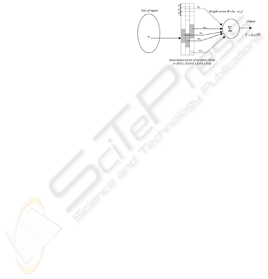
of generalization). Figure 4 shows a simplified or-
ganization of the receptive fields having 14 detectors
distributed on 3 layers. Being given that there is an
overlapping of the receptive fields, neighboring in-
puts will activate common detectors. Consequently,
this neural network is able to carry out a generaliza-
tion of the output calculation for inputs close to those
presented during learning.
Figure 4: Description of the simplified CMAC with 14 de-
tectors distributed on 3 layers. For each value of the in-
put signal, the number of activated detector is equal to 3.
A = [0, 0, 1, 0, 0, 0, 0, 1, 0, 0, 0, 1, 0, 0], Y = A(u)
T
W =
w
3
+ w
8
+ w
12
.
The output Y of the CMAC is computed by us-
ing two mappings. The first mapping projects an
input space point u into a binary associative vector
A = [a
1
..a
N
]. Each element of A is associated with
one detector and N is the number of detector. When
one detector is activated, the corresponding element
A of this detector is 1 otherwise it is equal to 0. The
second mapping computes the output Y of the net-
work as a scalar product of the association vector A
and the weight vector W = [w
1
..w
N
] (equation (5)).
Y = A(u)
T
W (5)
3.2 Learning Phase
During this learning phase, we use an intuitive control
allowing us to perform dynamic walking of our virtual
under-actuated robot without references trajectories.
This intuitive control strategy is based on three points:
• the observation of the relations between joint mo-
tions and the evolution of the parameters describing
the trajectory of the robot platform,
• an interpretation of the muscular behavior,
• the analysis of the intrinsic dynamics of a biped.
Based on these considerations, it is possible to deter-
mine a set of pragmatic rules. The objective of this
strategy is to generate the movements of the legs by
using a succession of passive and active phase. Also,
it is possible to modify step length, average velocity
AUTONOMOUS GAIT PATTERN FOR A DYNAMIC BIPED WALKING
29
by an adjustment of several parameters (12). Con-
sequently, this approach allow us to generate several
reference trajectories which are learned by several
CMAC neural networks.
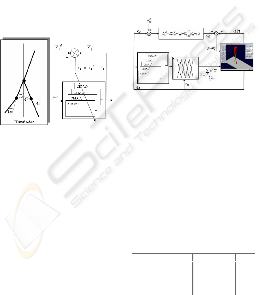
Figure 5 shows the method used during this training
phase. The trajectories of the swing leg (in terms of
joint positions and velocities) are learned with four
”single-input/single-output” CM AC
k
(k = 1, .., 4)
neural networks. Indeed, two CMAC are necessary to
memorize the joint angles q
i1
and q
i2
and two other
CMAC for angular velocities ˙q
i1
and ˙q
i2
. q
i1
and q
i2
are respectively the measured angles at the hip and
the knee of the leg i; ˙q
i1
and ˙q
i2
are respectively the
measured angular velocities at the hip and the knee of
the leg i.
Figure 5: Principle of the learning phase of CMAC neural
network (u = q
11
).
When leg 1 is in support (q
12
= 0), the angle q
11
is applied to the input of each CM AC
k
(u = q
11
)
and when leg 2 is in support (q
22
= 0), this is the an-
gle q
21
which is applied to the input of each CMAC
k
(u = q
21
). Consequently, the trajectories learned by
the neural networks are not function of time but func-
tion of the geometrical pattern of the robot. Further-
more, we consider that the trajectories of each leg in
swing phase are identical. This allow on the one hand
to divide by two the number of CMAC and on the
other hand to reduce the training time. The weights
of each CMAC
k
are updated by using the error be-
tween the desired output Y
d
k
of each CM AC
k
and the
computed output Y
k
of each CMAC
k
.
4 CONTROL STRATEGY USING
FUZZY-CMAC
Figure (6) shows the global strategy which is used to
control the walking robot. It should be noted that the
architecture of this control can be decomposed into
three parts:
• The first is used to compute the trajectory of the
swing leg from several output of the CMAC
k
neu-
ral networks and a Fuzzy Inference System.
• The second allows regulating the average velocity
from a modification of the desired pitch angle.
• The third is composed by four PD control in order
to ensure the tracking of the reference trajectories
at the level of each articulation.
Figure 6: Principle of the control strategy used Fuzzy-
CMAC trajectories.
4.1 Reference Trajectories
During the training stage, five trajectories with an
average velocity V
M
included in [0.4..0.8]m/s have
been learned by five CM AC
l
. Each CM AC
l
is
composed of four single input/single output CMAC
k
(two CMAC
k
for the angular positions q
i1
and q
i2
and two other CMAC
k
for the angular velocities ˙q
i1
and ˙q
i2
). Table 2 gives the main parameters which
are used during the learning phase according to the
desired average velocity V
M
, where V
M
is calculated
by using (1). q
d
r
and q
d
0
are respectively the desired
relative angle between the two thighs and the desired
pitch of the trunk. q
d
sw
corresponds to the desired an-
gle of the knee at the end of the knee extension of the
swing leg just before the double contact phase.
Table 2: Parameters used during the learning stage.
V
M
(m/s) q
d
r
(
◦
) q
d
sw
(
◦
) q
d
0
(
◦
)
CMAC
1
0.4 20 −7 3.5
CMAC
2
0.5 25 −10 3
CMAC
3
0.6 30 −15 2.5
CMAC
4
0.7 35 −20 8
CMAC
5
0.8 40 −25 8
ICINCO 2006 - ROBOTICS AND AUTOMATION
30
It must be pointed out that the step length L
step
increases when V
M
increases. Table (3) gives L
step
according to V
M
.
Table 3: V
M
and L
step
for the five references trajectories.
V
M
(m/s) L
step
(m)
CMAC
1
0.4 0.23
CMAC
2
0.5 0.28
CMAC
3
0.6 0.31
CMAC
4
0.7 0.36
CMAC
5
0.8 0.4
4.2 Fuzzy-CMAC Trajectories
During the walking, the measured angle q
11
, if leg 1
is in support, or q
21
, if leg 2 is in support, is applied
at each input of each CM AC
l
k
. The desired angular
position q
d
i1
and q
d
i2
, and the desired angular velocity
˙q
d
i1
and ˙q
d
i2
are carried out by using a fusion of the five
learned trajectories. This fusion is realized by using a
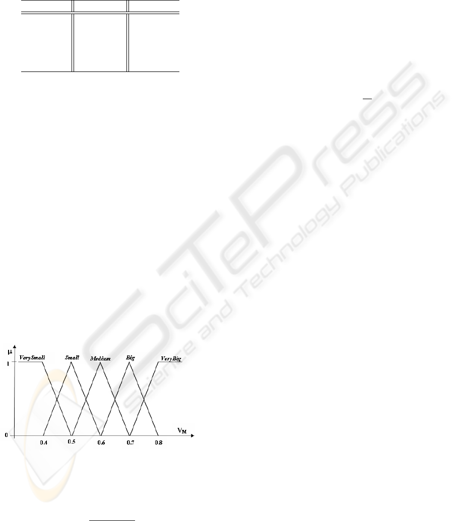
Fuzzy Inference System (FIS). This FIS is composed
of five rules:
• IF V
M
IS V erySmall THEN Y = Y
1
• IF V
M
IS Small THEN Y = Y
2
• IF V
M
IS Medium THEN Y = Y
3
• IF V
M
IS Big THEN Y = Y
4
• IF V
M
IS V eryBig THEN Y = Y
5
Where Y
l
corresponds at the output of the CMAC
l
.
Figure 7 shows the membership functions. The aver-
age velocity is modeled by five fuzzy sets (VerySmall,
Small, Medium, Big, VeryBig). Each desired trajec-
tory Y
k
is computed by using equation (6).
Figure 7: Membership functions used to compute the
FuzzyCMAC trajectories.
Y
k
=
P
5
l=1
µ
l
Y
l
k
P
5
l=1
µ
l
(6)
Consequently, the trajectory depends on the one
hand of the geometrical position of the stance leg and
on the other hand of the measured average velocity.
4.3 High Level Control
The high level control allows us to regulate the aver-
age velocity by adjusting the pitch angle of the trunk
at each step by using the error between the average
velocity V
M
and the desired average velocity V
d
M
and
of its derivative as described in figure 6.
At each step, ∆q
d
0
, which is computed by using the
error between V
M
and V
d
M
and of its derivative (equa-
tion 7), is then added to the pitch angle of the previous
step q
d
0
(n) in order to carry out the new desired pitch
angle of the following step q
d
0
(n + 1) as shown in
equation (8).
∆q
d
0
= K
p
(V
d
M
− V
M
) + K
v
d
dt
(V
d
M
− V
M
) (7)
q
d
0
(n + 1) = q
d
0
(n) + ∆q
d
0
(8)
4.4 PD Control
In order to ensure the tracking of the desired trajecto-
ries, the torques T
knee
and T
hip
applied respectively
at the knee and at the hip are computed by using PD
control. During the swing stage, the torques are car-
ried out by using equations (9) and (10). q
d
ij
and
˙q
d
ij
are respectively the reference trajectories (position
and velocity) of the swing leg from the output of the
Fuzzy-CMAC (j = 1 for the hip, j = 2 for the knee).
T
sw
hip
= K
p
hip
(q
d
i1
− q
i1
) + K
v
hip
( ˙q
d
i1
− ˙q
i1
) (9)
T
sw
knee
= K
p
knee
(q
d
i2
− q
i2
) + K
v
knee
( ˙q
d
i2
− ˙q
i2
) (10)
Secondly, the knee of the stance leg is locked, with
q
d
i2
= 0 and ˙q
d
i2
= 0 (equation 11), and the torque
applied to the hip allows to control the pitch angle of
the trunk (equation 12). q
0
and ˙q
0
are respectively the
measured absolute angle and angular velocity of the
trunk. q
d
0
is the desired pitch angle.
T
st
knee
= −K
p
knee
q
i2
− K
v
knee
˙q
i2
(11)
T
st
hip
= K
p
trunk
(q
d
0
− q
0
) − K
v
trunk
˙q
0
(12)
5 RESULTS
The control strategy presented in section 4 allows:
• To generate the joint trajectories of the swing leg
from the geometrical configuration of the robot and
the real average velocity.
• To regulate, at each step, the average velocity
thanks to an adjustment of the pitch angle.
AUTONOMOUS GAIT PATTERN FOR A DYNAMIC BIPED WALKING
31
The main interest of this approach is that the walk-
ing robot is autonomous and is able to adapt, for ex-
ample, the step length from only one parameter: the
average velocity. Furthermore, if the robot is pushed
forwards, the average velocity increases and conse-
quently the step length increases too. In this manner,
it is easier for the robot to compensate this kind of
perturbation.
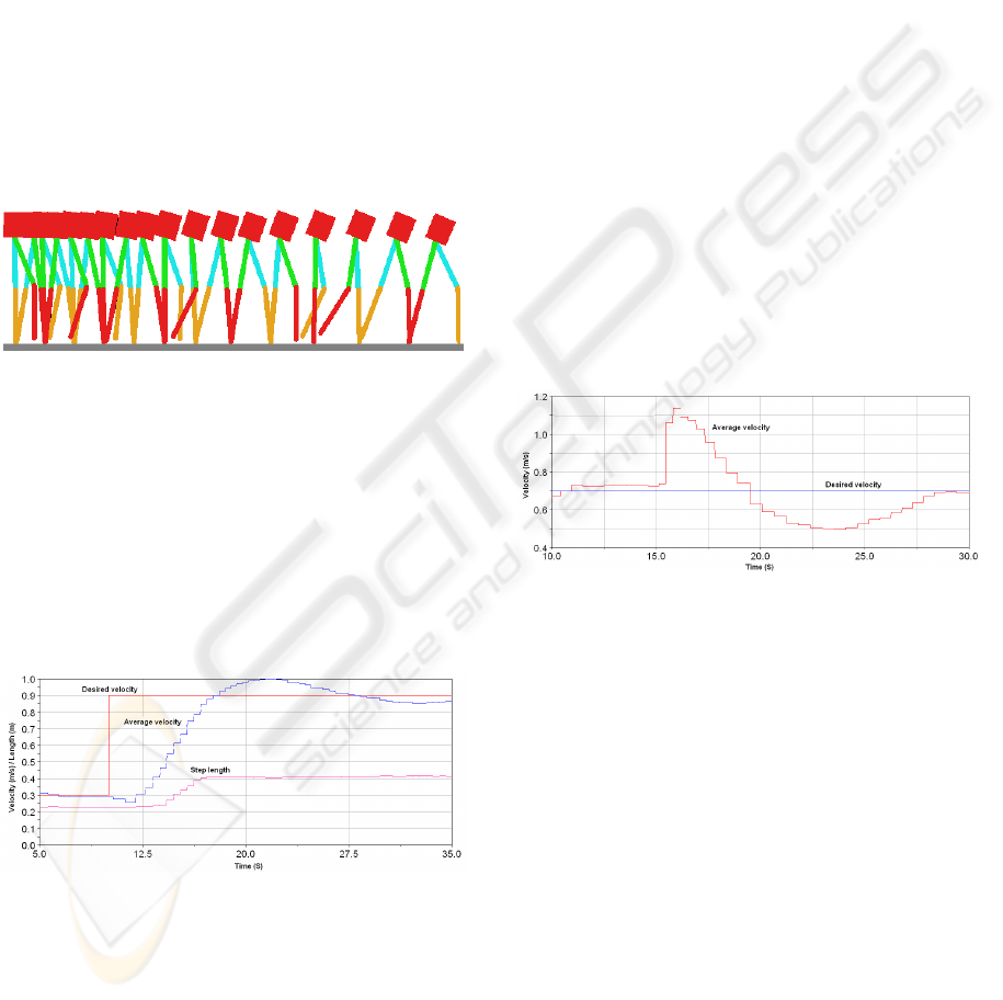
5.1 Autonomous Walking Gait
Figure 8 shows the stick diagram of the walking of
the robot when the desired average velocity increases.
It must be noticed that the control strategy allows to
adapt automatically the pitch angle and the step length
as the human being.
Figure 8: Stick diagram of the walking robot when the av-
erage velocity increases.
Figure 9 shows the desired average velocity V
d
M
,
the measured velocity V
M
(equation 1) and the step
length L
step
. When V
d
M
increases from 0.3m/s
to 0.9m/s, V
M
increases gradually and converges
fowards the new value of V
M
. L
step
increases au-
tomatically from 0.25m to 0.4m from the measured
average velocity at each step.
Figure 9: Average velocity and step length when the desired
average velocity increase from 0.3m/s to 0.9m/s.
It must be pointed out that the walking gait can de-
pends to the desired average velocity V
d
M
. But in this
case, the step length transition is abrupt. Furthermore,
the fact that the walking gait depends of the measured
average velocity allows increasing the robustness of
the walking of the robot.
5.2 Evaluation of the Robustness
According to a Pushed Force
During walking, a robot moving in real environment
can be subjected to external forces involving an im-
balance. Consequently, the control strategy must react
quickly in order to compensate this perturbation and
to avoid the fall of the robot. Generally, when human
being is pushed forwards, he increases the step length.
In the case of the proposed control strategy, the step
length depends of the real average velocity V
M
. If
the robot is pushed forwards, the duration of the step
t
step
decreases and consequently, V
M
increases. In
this manner, at the next step after this perturbation,
L
step
is adjusted.
The figure 10 shows the evolution of the average
velocity before and after the force perturbation. At
t = 15s, we applied on the trunk of the robot an im-
pulsive pushed force. The duration and the amplitude
of this force are respectively 0.2s and 50Nm. Before
this perturbation, the robot walks with an average ve-
locity to 0.7m/s which corresponds at the desired av-
erage velocity. After this perturbation, V
M
increases
considerably but our control strategy allow to com-
pensate slowly this perturbation.
Figure 10: Average velocity V
M
when the robot is pushed
forwards at t = 15s.
The figures 11 and 12 show respectively the evolu-
tion of the step length and the pitch angle of the trunk.
It must be pointed out that:
• L
step
is adjusted automatically from the measured
average velocity.
• The pitch angle of the trunk q
d
0
decreases just after
the application of the pushed force in order to slow
down the velocity of the progression of the robot.
6 CONCLUSION
In this paper, we have proposed an autonomous gait
pattern for a dynamic biped walking. Our approach
is based firstly on Fuzzy-CMAC issued computation
of robot’s swing leg’s desired trajectory and secondly
on a high level control strategy allowing regulation
ICINCO 2006 - ROBOTICS AND AUTOMATION
32
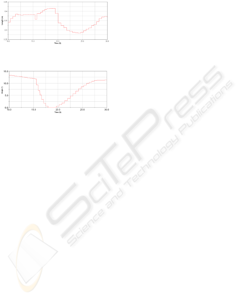
Figure 11: Step length L
step
when the robot is pushed for-
wards at t = 15s.
Figure 12: Pitch angle of the trunk when the robot is pushed
forwards at t = 15s.
of the robot’s average velocity. The main interest of
this approach is to proffer to the walking robot au-
tonomy and adaptability involving only one parame-
ter: the average velocity. The obtained results show
the adaptability of the walking step length and the
issued additional robustness of the proposed control
strategy. In fact, when the robot is pushed forwards,
the average velocity increases and consequently the
step length increases too. In this manner, it is easier
to compensate this kind of perturbation.
Future works will focus firstly on the extension of
the Fuzzy-CMAC approach in order to increase the
autonomy of the walking robot according to the na-
ture of the environment (get up and down stairs for
instance), avoidance and dynamic crossing obstacles
and secondly on the experimental validation of our
approach.
REFERENCES
Y. Sakagami, R. Watanabe, C. Aoyama, S. Matsunaga, N.
Higaki, K. Fujimura. The intelligent ASIMO: system
overview and integration. Proc. IEEE Conf. on Intelli-
gent Robots and Systems, 2002, 2478–2483.
K. Kaneko, F. Kanehiro, S. Kajita, H. Hirukawa, T.
Kawasaki, M. Hirata, K. Akachi, T. Isozumi. Hu-
manoid robot HRP-2. Proc. IEEE Conf. on Robotics
and Automation, 2004, 1083–1090.
M. Vukobratovic, B. Borovac. Zero moment point - thirty
five years of its live. International Journal of Hu-
manoid Robotics, 2004, Vol.1 N
◦
1, 157–173.
S. Kajita, F. Kanehiro, K. Kaneko, K. Fujiwara, K. Harada,
K. Yokoi and H. Hirukawa. Biped walking pattern
generation by using preview control of Zero-Moment
Point Proc. IEEE Conf. on Robotics and Automation,
2003, 1620–1626.
Q. Huang, K. Yokoi, S. Kajita, K. Kaneko, H. Arai, N. Koy-
achi, K. Tanie. Planning walking patterns for a biped
robot. IEEE Transactions on Robotics and Automa-
tion, 2001, Vol.17, N
◦
3, 280–289.
K. Hirai, M. Hirose, Y. Haikawa, T. Takenaka. The devel-
opment of honda humanoid robot. Proc. IEEE Conf.
on Robotics and Automation, 1998, 1321–1326.
C. Chevallereau, G. Abba, Y. Aoustin, F. Plestan, E.R.
Westervelt, C. Canudas-de-Wit, J.W. Grizzle. RAB-
BIT: A testbed for advanced control theory. IEEE
Control Systems Magazine, 2003, Vol.23, N
◦
5, 57–79.
http://robot-rabbit.lag.ensieg.inpg.fr/
http://www.laas.fr/robea/
C. Sabourin, O. Bruneau. Robustness of the dynamic walk
of a biped robot subjected to disturbing external forces
by using CMAC neural networks. Robotics and Au-
tonomous Systems, 2005, Vol.23, 81–99.
E.R. Westervelt, Gabriel Buche, J.W. Grizzle. Experimental
validation of a framework for the design of controllers
that induce stable walking in planar bipeds. The Inter-
national Journal of Robotics Research, 2004, Vol.23
N
◦
6, 559–582.
C. Sabourin, O. Bruneau, J-G.Fontaine. Start, stop and tran-
sition of velocities on an underactuated bipedal robot
without reference trajectories. Internationnal Journal
of Humanoid Robotics, 2004, Vol.1, N
◦
2, 349–374.
O. Bruneau, F.B. Ouezdou. Distributed ground/walking
robot interactions. Robotica, Cambridge University
Press, 1999, Vol.17, N
◦
3, 313–323.
J. S. Albus. A new approach to manipulator control:
the cerebellar model articulation controller (CMAC).
Journal of Dynamic Systems, Measurement and Con-
trol, (1975), 220–227.
J. S. Albus. Data storage in the cerebellar model articula-
tion controller (CMAC). Journal of Dynamic Systems,
Measurement and Control, 1975, 228–233.
W. T. Miller, F. H. Glanz, L. G. Kraft. CMAC: An asso-
ciative neural network alternative to backpropagation.
Proceedings of the IEEE, Special Issue on Neural Net-
works, vol.78, N
◦
10, 1990, 1561-1567.
A. L. Kun, T. Miller. The design process of the unified walk-
ing controller for the UNH biped. Proc. IEEE Conf. on
Humanoid Robots, 2000.
A. Brenbrahim, J. Franklin. Biped dynamic walking us-
ing reinforcement learning. Robotics and Autonomous
Systems, 1997, Vol.22 , 283–302.
AUTONOMOUS GAIT PATTERN FOR A DYNAMIC BIPED WALKING
33
