
A SAFETY SYSTEM FOR DYNAMIC VACUUM LIQUID
NITROGEN PIPELINE
For World Class Manufacturing Operation in Semiconductor Industry
Vinayak Divate
Spansion (thailand) Limited,Industrial Engineering , 229 Moo4 Changwattana Road Pakkred Nonthaburi Thailand 1120
Pichit Saengpongpaew
Spansion (thailand) Limited,Industrial Engineering , 229 Moo4 Changwattana Road Pakkred Nonthaburi Thailand 1120
Keywords: Liquid Nitrogen (Ln2).
Abstract: Liquid nitrogen is a colourless, odourless, extremely cold liquid and gas under pressure. It can cause rapid
suffocation when concentrations are sufficient to reduce oxygen levels below 19.5%. Contact with liquid or
cold vapors can cause severe frostbite. One volume of liquid nitrogen will expand to produce 696.5
equivalent volumes of gas. With this background Ln2 is being used in Semiconductor industry especially in
testing operation. The cold tests are taken on products at a temp up to -40C to -60C. The Ln2 is used in
testing machine to reduce test handler chamber temp. The chamber temp is required to maintain at -40 C
with allowance of + or – 3C to get accurate results. So this paper describes how Dynamic Vacuum ln2
pipeline system can be maintained smartly to get maximum benefits with minimum unscheduled shutdown
in semiconductor industry. This paper also gives the details about the safety system developed at
SPANSION Thailand limited for handling of ln2 through Dynamic vacuum ln2 pipeline system.
1 INTRODUCTION
In semiconductor industry Ln2 is handled in two
ways. 1) PLC (Portable liquid cylinders) is filled
from main cylinder and then PLC is moved from
filling station to tester machine. 2) Direct Ln2
pipeline system from main cylinder to Test chamber.
There are many advantages of direct pipeline system
over PLC, provided the ln2 requirement is more than
100KCum./month. Filling of PLC cylinders from
main tank involves loss of Ln2. The liquid turns into
gas. There are handling issues like weight of PLC,
quality of vacuum at PLC so on. So it is always
better to transfer Ln2 through piping system,
provided usage is more than 100KCum./month . Or
if the manufacturing requires to fill more than 15
PLCs /day with 200Kg /PLC. The Ln2 is handled in
various ways. The boiling point of ln2 is -195.8C.
So, it is very difficult to handle Ln2 in a liquid state.
In cold testing operation the handler chamber
required to get Ln2 in a liquid state. If ln2 is
provided in a gas state there is no heat absorption at
test chamber and it is considered as a loss of ln2. So
there are various methods of supplying of ln2. The
first and oldest type of supply system used simple
copper or stainless steel pipe wrapped with wood
insulation. Wood was later replaced by mica, then
shortly after polyurethane foam. Foam insulation is
highly inefficient and cumbersome, much of the
liquid nitrogen traveling through the pipe turns to
gas and pipe diameters with insulation are often over
8 inches. These large, bulky, inefficient piping
systems were relatively cheap to install, but the loss
of liquid nitrogen makes them to be very expensive
in the long run. Vacuums are one of the best ways to
eliminate heat conduction, so finally a dynamic
vacuum piping system was developed. This piping
system uses a pipe inside a pipe. To maintain a
thermo-arresting vacuum, the ultimate insulator,
between the two layers a vacuum pump is attached
to the line. The vacuum pump works continuously
twenty four hours seven days a week.
The dynamic vacuum piping system dramatically
decreased heat loss, and therefore was a much more
148
Divate V. and Saengpongpaew P. (2006).
A SAFETY SYSTEM FOR DYNAMIC VACUUM LIQUID NITROGEN PIPELINE - For World Class Manufacturing Operation in Semiconductor Industry.
In Proceedings of the Third International Conference on Informatics in Control, Automation and Robotics, pages 148-153
DOI: 10.5220/0001210401480153
Copyright
c
SciTePress

efficient system. While the dynamic system is much
more effective than foam, materials and installation
cost much more, and the time and maintenance
required for the pumping system is highly cost
ineffective due to electricity consumption.
Table 1: HAZOP table.
Guide
Word
Deviation Ln2
line
needs
to
stop?
Consequences Causes Suggest
ed
Action
More 120psi
Pressure
at PG1
No
need
Alarm will be
at 120 psi
VENTS
are off
no
handler
ON
Start
handler ,
check
VENT
There are four principal areas of hazard related to
the use of
Ln2. These are: flammability, high pressure gas,
materials, and personnel. All categories of hazard
are usually present in a system concurrently, and
must be considered when introducing a Ln2 system
or process The high pressure gas hazard is always
present when ln2 is used or stored. Since the
liquefied gases are usually stored at or near their
boiling point, there is always some gas present in the
container. The large expansion ratio from liquid to
gas provides a source for the build-up of high
pressures due to the evaporation of the liquid. The
rate of evaporation will vary, depending on the
characteristics of the fluid, container design,
insulating materials, and environmental conditions
of the atmosphere. Container capacity must include
an allowance for that portion which will be in the
gaseous state. These same factors must also be
considered in the design of transfer lines and piping
systems A very brief contact with ln2 at -195.8C
temperatures is capable of causing burns similar to
thermal burns from high temperature contacts.
Prolonged contact with these temperatures will
cause embitterment of the exposed members because
of the high water content of the human body. The
eyes are especially vulnerable to this type of
exposure, so that eye protection is necessary.
1.1 Designing Safety System for
Dynamic Vacuum Pipeline
The HAZOP study is done for Dynamic vacuum
pipeline system but it is done before installation of
pipeline. HAZOP: It is a hazard and operability
study. The Hazops procedure involves taking a full
description of a process and systematically
questioning every part of it to establish how
deviations from the design intent can arise. Once
identified, an assessment is made as to whether such
deviations and their consequences can have a
negative effect upon the safe and efficient operation
of the manufacturing plant. If considered necessary,
action is then taken to remedy the situation. This
study helps to design the safety system required for
Dynamic vacuum ln2 pipe line system. An essential
feature in this process of questioning and systematic
analysis is the use of keywords to focus the attention
of the team upon deviations and their possible
causes. These keywords are divided into two sub-
sets:
Primary Keywords which focus attention upon a
particular aspect of the design intent or an associated
process condition or parameter. Secondary
Keywords which, when combined with a primary
keyword, suggest possible deviations. The entire
technique of Hazops revolves around the effective
use of these keywords, so their meaning and use
must be clearly understood by the team. Examples of
often used keywords are listed below. Primary
words: Incase of Dynamic vacuum pipeline system
is Pressure, Vacuum, Temp, and Flow etc.
Secondary words: More, less, In the HAZOP study
we have to write a report on Purpose, Objective, and
Scope of study, Team members, and Data collection
by team members in following format. Showed in
Table 1.
But it has been observed that the users do not install
sufficient safety system while installation of
Dynamic vacuum pipeline system. For long term
success of Dynamic vacuum pipe line, it is very
clear that control over vacuum, and pressure are very
important. Usually, the manufacturers design
Dynamic vacuum pipeline system with many safety
release valves (SRV) to stop over pressurization.
Usually these valves are present at both sides of any
ln2 valve. Typically SRV operates at 120PSI,
170PSI as per requirement. But it is a one kind of
breakdown maintenance. It means, if the pressure
goes more than 120PSI the SRV fires. But one
important point is ignored and that it the firing of
SRV happens inside production floor. The ln2 gets
fired with smoky jet with loud cranking noise. It is
big disturbance to all operators around the line. It
also may decrease the percentage of O2 in
atmosphere. So, the operators need to go away from
work place causing production disturbance. Any
production disturbance can cost thousands of dollars.
So it is required to control the pressure with different
perspective. The Dynamic vacuum line should have
an additional safety system which should alarm on
over pressurization. The SRV is needed but that
should be the last choice. The control over vacuum
A SAFETY SYSTEM FOR DYNAMIC VACUUM LIQUID NITROGEN PIPELINE - For World Class Manufacturing
Operation in Semiconductor Industry
149
is also very important. Usually the manufactures
gives vacuum meters to monitor vacuum in the line.
But additional alarm system should be there to get
an alarm as soon as the vacuum is out of control.
Usually the vacuum slowly reduces if there is failure
of sealing. The gaskets or sealing fails over time
because of wear and tear. The user can make
necessary arrangement by controlling vacuum zone
valves. To describe a safety system let consider a
Dynamic vacuum pipe line system. The typical
picture is shown.
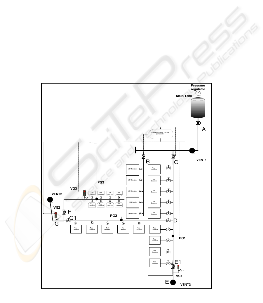
1.2 Designing of Dynamic Vacuum
Pipeline System
A typical Dynamic vacuum system fig1 is designed
to illustrate. The main tank is located at A, ideally
there should not be any pressure regulator on the
Dynamic vacuum pipeline; the pressure regulator
either expands or restricts the area of cross-section
and creates gas from liquid. Our main aim is to
provide 100% liquid nitrogen to test chamber. It can
not be 100% but we should tray to design a system
which can capable of supplying approximately
100% liquid. There is a main valve at A. The VENT
1 is installed to remove gas from liquid. The main
cylinder can not be a reservoir of 100% Ln2. So,
VENT1 is used to remove gas from liquid when
liquid flow from main tank to test chamber. Sub
main valves B and C are pneumatic actuated valves.
These vales can be opened and closed with N2 gas
supply ON and OFF. There are two more sub main
valves at F and D .These valves are installed to get
maximum flexibility. The flexibility of pipeline is
explained at the end of this article.
These are manual. VENT3 and VENT2 are
connected at the end of each line to achieve closed
loop pipe line. All generated gas in pipe line is
thrown away. PG1, PG2, PG3 are the pressure which
are installed just before end of line. They must be
installed just before end of line so that you can get
Figure 1: diagram of Dynamic Vacuum ln2 direct line.
ICINCO 2006 - SIGNAL PROCESSING, SYSTEMS MODELING AND CONTROL
150
normalized pressure of that pipe section.VG1, VG2,
VG3 are installed at the end of pipeline so that we
can get a minimum vacuum achieved at the end of
line. It ensures that the recorded vacuum is certainly
present in that pipe section. The computerized
control
system is installed to control pneumatic valves at B
and C. It also monitors the signals from pressure
gauges and vacuum gauges.
2 SAFETY CONTROL SYSTEM
The safety control system has three parts A)
Monitoring and evaluation B) Audit review and
improvement and C) Emergency plan. To satisfy all
three requirements, two types of safety control
systems should be installed after installation of
Dynamic vacuum ln2 line. 1) Monitoring and
evaluation: It means the Dynamic vacuum system
should be real monitored for vacuum and pressure
parameters along the pipeline. The monitored results
should be compared or evaluated real time with set
limits. If there is any gap appropriate alarm system
should be ON real-time automatically. 2) Audit
review and improvement: For audits the old data is
required. So, the safety system should be capable of
producing the old data. There must be secured data
base and all vacuum and pressure parameters must
be stored real-time for future reference. Audits must
be done; Process capability index like Cpk must be
calculated automatically. C) Emergency plan: The
system should stop the supply of Ln2 from the main
tank in case of emergency. The emergency limits
must be evaluated and set with control system.
With this requirement the two kinds of safety
systems must be there along with Dynamic vacuum
pipeline system.
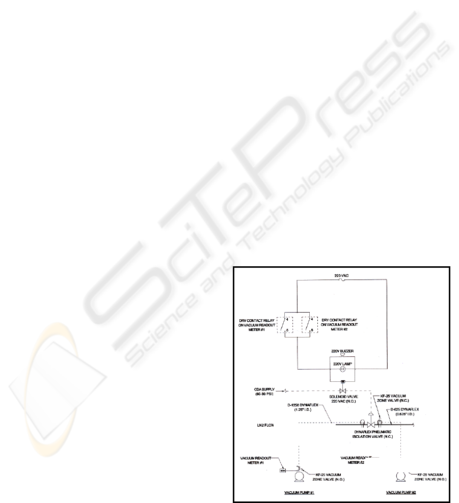
Analog control and alarm system. Shown in fig2;
As we know pressure and vacuum are the key
parameters; so, hardware should be selected in such
a way that it gives analog and digital signal. Usually
vacuum or pressure probe senses the pressure; it is
then collected by a meter which creates digital and
analog signal. Now let consider figure for the the
Dynamic vacuum pipeline system mentioned in fig3.
VG1, VG2, VG3 are the vacuum meters which send
analog and digital signal to control panel. The signal
transfer is explained in fig. We can set two limits in
vacuum meter lower and upper. So let us consider a
Dynamic vacuum pipeline whose vacuum is
controlled at 1mtor. The vacuum meter is set at
15mtor to give lower alarm and 30mtor to give
upper alarm. In normal working condition vacuum
meter should show reading 1mtor with some
allowance. But if there is any problem and vacuum
decreased to 15mtorr then vacuum meter sends
analog signal to control panel to activate lower
alarm. If the vacuum further decreased to 30m tor
the vacuum meter sends an upper alarm.
The control panel is equipped with relay circuit as
shown in fig 2. If it receives lower alarm then it will
make buzzer ON and a yellow light will start
blinking. If vacuum meter gets upper alarm it
actuates circuit to get Buzzer ON, red light starts
blinking it shuts off the solenoid valve which is
operated on gas .The valve shuts down. If you see
figure 5 and if VG1 senses the upper alarm then the
corresponding signal will go to controller; the
controller will actuate the signals to solenoid valves
at B and C. It will shut down the flow of Ln2 to all
Dynamic vacuum pipe line.
Digital Computerized Alarm and Control System.
Incase of digital control system see figure 3 & 4.
The vacuum and pressure meters give corresponding
digital signal. The signal comes by RS232. But
usually the computers are placed at controlling room
far from production floor. So we need to convert
signal from RS232 to RS422 to achieve better
accuracy. RS232 can be used when the computer is
not more than 50m away from vacuum or pressure
sensor. In above case RS422signal again converted
to RS232 at computer. The computer is installed
with multi COM cards. So a computer is capable of
receiving 15 signals from vacuum or pressure meters.
Figure 2: Analog control system.
Isolation Valve
Zone
Valve
Zone Valve
Zone
Valve
Pipe line
A SAFETY SYSTEM FOR DYNAMIC VACUUM LIQUID NITROGEN PIPELINE - For World Class Manufacturing
Operation in Semiconductor Industry
151
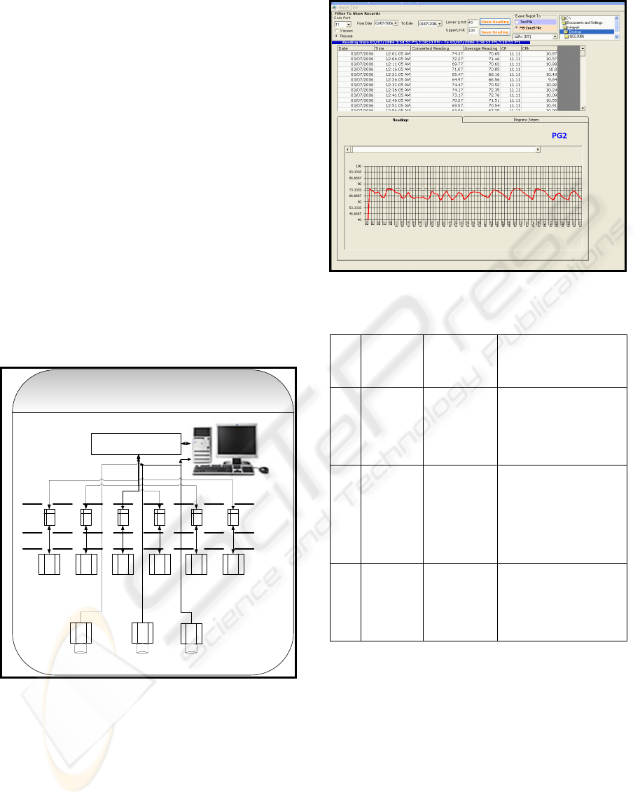
Now in above case customized software is designed
and developed which is capable of capturing the data
at COM ports. The data is stored in a secured data
base for future reference. So the software is capable
of sending and receiving data from sensors. The Cpk
is automatically calculated to get online process
capability index. The software is capable of plotting
real time data on statistical process control charts. It
is shown in the fig4
3 FLEXIBILITY OF DYNAMIC
VACUUM PIPE LINE
This is one more concept which must be taken into
consideration while designing of Dynamic vacuum
ln2 line. It is little costly to design a flexible line but
in long term it gives a lot of benefits. This concept is
especially useful when the manufacturing requires
zero down time. If the line is flexible, we can use the
line partially, avoiding total 100% shutdown.
COMPUTRIZED DIGITAL CONTROL SYSTEM
RS422 TO RS232
CONVERTOR
VG1
RS232
Computer with multiplw COM RS232 ports
Camera1
PG3VG2PG1
VG3VG2
Camera2 Camera3
RS232
RS422
Convertor
Sensor
Figure 3: Digital control safety system.
So, if the above Dynamic vacuum pipeline is
considered shown in fig 1. The pipeline is divided
into three parts Part A.
Figure 4: UI digital monitoring and data storage.
Table 2: Flexibility of Dynamic Vacuum line.
Sr .
No
Part of
Dynamic
vacuum
line
Number of
Outlets
Flexibility
1
Part 1-B
to F 13
13
If problem is in part1,
then close valve at B and
F;
Part 2 and 3 will get Ln2
from Valve C with
closed
2
Part 2 – C
to D to E
9
9
If problem is in Part 2 ,
Close the valves at C and
E1, D. The ln2 will come
to Part 1 and 3 from
valve
B to F to E giving closed
loop.
3
Part 3-D
to G 5
5
If the problem is in
Part3, Close the valve at
D, G1
still part 1 and 2 will
work as closed loop
pipeline.
4 RECOVERY ON BREAKDOWN
OF DYNAMIC VACCUUM LN2
PIPE LINE
In semiconductor industry the breakdown of any
utility system is a big crime. The testers are highly
expensive so, utilization of machines is very
important. Now if we consider break down of
Dynamic Vacuum system then it is more
troublesome as the Dynamic Vacuum ln2 line can
not be started unless the vacuum is back to normal
ICINCO 2006 - SIGNAL PROCESSING, SYSTEMS MODELING AND CONTROL
152
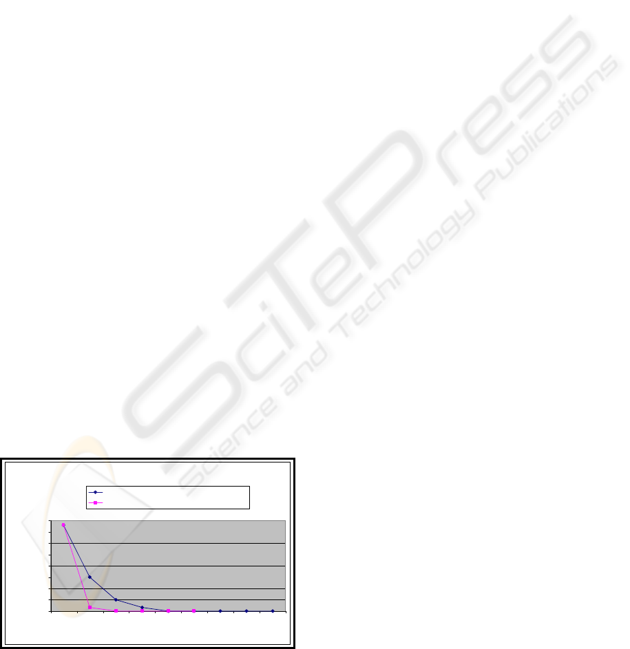
level. So normally it takes 8 to 9 hrs for a section of
pipe of 100 feet by three vacuum pumps. In
SPANSION Thailand this problem is solved by
experimenting with Dynamic Vacuum line. In
SPANSION Thailand the vacuum pumps and
vacuum zone valves are arranged in such a way that
the 100 feet Dynamic Vacuum line can be
vacuumized by three pumps within 2 hrs. It is
achieved as follows.
a) N2 gas supply is arranged at four points
along Dynamic Vacuum line.
b) Three vacuum pumps at three equal
distances along 100 feet are suitable
installed. Vacuum zone valves are directed
in such a way that all pumps will pump
approximately 33 m of 100feet Dynamic
Vacuum line.
c) At starting, make all three pumps ON and
we have to purge N2 gas at liquid line and
vacuum line for 15 mins to remove
humidity.
d) Stop purging N2 gas at vacuum line and
pump vacuum for another 30 mins .
e) Stop N2 gas purging at liquid line and open
Ln2 to make all line cold enough to close
all micro holes along 100 feet Dynamic
Vacuum line for five mins at pressure 70psi.
f) The liquid is very cold and closes all micro
holes, the vacuum pumps gives very good
performance as there is no humidity.
g) Now pump for another 1 hr 10 mins ,
vacuum with partial ln2 in liquid line and
vacuum line with no humidity .
h) We can achieve vacuum at desired level of
50 to 60 mtorr in two to three hours. Now
we can open a liquid line fully to give ln2
to handlers.
Old method V/s New method
0
100000
200000
300000
400000
500000
600000
700000
800000
123456789
Time(hrs)
Vaccuum (mtorr)
old method : 100 feet pipe line for three pumps
New method :100 feet with three vaccuum pump.
Figure 5: Recovery on Breakdown.
5 CONCLUSION
We can say that Dynamic vacuum pipeline system is
the best choice if requirement of Ln2 is large at
manufacturing. Secondly the user must install or
invest sufficient money in customized development
of safety systems. The vacuum and pressure control
are the key elements .The two kinds of safety
systems must be installed, analog and digital. Both
systems give a lot of benefits in maintaining a
Dynamic vacuum ln2 line 24 hours 7 days week ON
without any accident. Analog system should be set at
two levels of alarm system. The first alarm is
precautionary alarm and the second alarm is for
system shut down. Digital system must be equipped
with good database design, customized user
interface, real time system for monitoring the signals.
The pressure at throughout Dynamic vacuum line
should be maintained as low as possible. It should be
controlled at main tank with tank mechanism. The
pressure regulators are loss making devices so,
should be avoided. The line should flexible enough
so that there will not be total shutdown of system. In
semiconductor industry recovery from system
breakdown should be in minimum time so proper
contingency plan and Dynamic Vacuum system
must be installed accordingly.
REFERENCES
http://www.vbsflex.com/dynamic vacuum .html
http://www.isograph-software.com/hazover.htm
Spansion Thailand EHS specs
Objectifying Real-Time Systems/Book and Disk by John
Ellis
Real-Time Systems Design and Analysis by Phillip A.
Laplante
A SAFETY SYSTEM FOR DYNAMIC VACUUM LIQUID NITROGEN PIPELINE - For World Class Manufacturing
Operation in Semiconductor Industry
153
