
FUZZY LOGIC BASED UAV ALLOCATION AND
COORDINATION
James F. Smith III, ThanhVu H. Nguyen
Code 5741, Naval Research Laboratory, Washington, DC, 20375-5320, USA
Keywords: Decision support systems, distributed control systems, fuzzy control, knowledge-based systems
applications, software agents for intelligent control systems
Abstract: A fuzzy logic resource allocation algorithm that enables a collection of unmanned aerial vehicles (UAVs) to
automatically cooperate will be discussed. The goal of the UAVs’ coordinated effort is to measure the
atmospheric index of refraction. Once in flight no human intervention is required. A fuzzy logic based
planning algorithm determines the optimal trajectory and points each UAV will sample, while taking into
account the UAVs’ risk, risk tolerance, reliability, and mission priority for sampling in certain regions. It
also considers fuel limitations, mission cost, and related uncertainties. The real-time fuzzy control
algorithm running on each UAV renders the UAVs autonomous allowing them to change course
immediately without consulting with any commander, requests other UAVs to help, and change the points
that will be sampled when observing interesting phenomena. Simulations show the ability of the control
algorithm to allow UAVs to effectively cooperate to increase the UAV team’s likelihood of success.
1 INTRODUCTION
Knowledge of meteorological properties is
fundamental to many decision processes. Due to
personnel limitations and risks, it is useful if related
measurement processes can be conducted in a fully
automated fashion. Recently developed fuzzy logic
based algorithms that allow a collection of
unmanned aerial vehicles (UAVs) and an
interferometer platform (IP) (Smith 2005) to
automatically collaborate will be discussed. The
UAVs measure the index of refraction in real-time to
help determine the position of an electromagnetic
source (EMS). The IP is actually an airplane with
an interferometer onboard that measures emissions
from the electromagnetic source whose position is to
be estimated. Each UAV has onboard its own fuzzy
logic based real-time control algorithm. The control
algorithm renders each UAV fully autonomous; no
human intervention is necessary. The control
algorithm aboard each UAV will allow it to
determine its own course, change course to avoid
danger, sample phenomena of interest that were not
preplanned, and cooperate with other UAVs.
Section 2 provides an overview of the
meteorological sampling problem and a high level
description of the planning and control algorithms
that render the UAV team fully autonomous.
Section 3 discusses the electromagnetic
measurement space, UAV risk, and the planning
algorithm. Section 3 also discusses the UAV path
construction algorithm that determines the minimum
number of UAVs required to complete the task, a
fuzzy logic based approach for assigning paths to
UAVs and which UAVs should be assigned to the
overall mission. Section 4 describes the control
algorithm that renders the UAVs autonomous.
Section 4 also describes the priority for helping (PH)
algorithm, a part of the control algorithm based on
fuzzy logic that determines which UAV should help
another UAV requesting help. The three subclasses
of help requests are also discussed in this section.
Section 5 discusses experimental results including
UAV path determination, UAV path assignment,
determination of which UAVs should fly the
mission and the result of a request for help during
the mission. Finally, section 6 provides a summary.
9
F. Smith III J. and H. Nguyen T. (2006).
FUZZY LOGIC BASED UAV ALLOCATION AND COORDINATION.
In Proceedings of the Third International Conference on Informatics in Control, Automation and Robotics, pages 9-18
DOI: 10.5220/0001211800090018
Copyright
c
SciTePress

2 METEOROLOGICAL
SAMPLING AND
COOPERATIVE
AUTONOMOUS PLATFORMS
For many applications it is useful to be able to make
meteorological measurements in real-time.
Examples include determining the index of
refraction of the atmosphere to facilitate geo-
location (Smith 2005); determination of the presence
and extent of such phenomena as radio holes and
ducts, which may interfere with communications;
tracking atmospheric contaminants (Spears 2005);
and sand suspended in the atmosphere that can
interfere with sensors.
The fuzzy logic based planning and control
algorithms that have been developed allow a
collection of UAVs making up the UAV team to
engage in cooperative sampling of the atmosphere in
real-time without human intervention. Each UAV
will have its own control algorithm allowing it to
determine new optimal trajectories in real-time
subject to changing conditions. Also, the control
algorithm on the UAVs will allow them to cooperate
to increase the probability of mission success. There
will be two different types of cooperation allowed
by the control algorithm and three classes of help
requests which are discussed in section 4.
3 PLANNING AND RISK
The measurement space consists of the
electromagnetic propagation environment where
UAVs and the IP make their measurements. This
environment includes sample points and the
desirable neighborhoods that surround them. The
sample points or the desirable neighborhoods are
where the UAVs will make measurements. The
method of determining the sample points and
desirable neighborhoods is described below.
The measurement space also includes taboo
points and the undesirable neighborhoods that
surround them. The taboo points are points of
turbulence and other phenomena that could threaten
the UAVs. The undesirable neighborhoods
surrounding them also represent various degrees of
risk. The method of specifying taboo points and
quantifying the degree of risk associated with their
undesirable neighborhoods employs fuzzy logic and
is discussed in this section.
The planning algorithm allows the determination
of the minimum number of UAVs needed for the
mission subject to fuel constraints, risk, UAV cost,
and importance of various points for sampling. Risk
refers to turbulent regions or regions undesirable for
other reasons, e.g., the presence of enemy observers
or physical obstructions. The planning algorithm
automatically establishes the order in which to send
the UAVs taking into account the UAV’s value;
onboard sensor payload; onboard resources such as
fuel, computer CPU and memory; etc. The priority
of sample points and their desirable neighborhoods
are taken into account. The planning algorithm also
calculates the optimal path around undesirable
regions routing the UAVs to or at least near the
points to be sampled.
In the planning phase, the location of the EMS is
unknown. Some positions are more likely than
others for the EMS’s location. When establishing
likely positions for the EMS, human experts are
consulted. The experts provide subjective
probabilities of the EMS being located at a number
of positions. These likely EMS locations are
referred as hypothesis positions. Ray-theoretic
electromagnetic propagation (Blake 1986) is
conducted from each hypothesis position to each
interferometer element on the IP. The points on the
sampling grid nearest the points of each ray’s
passage are the sample points. The priority of a
sample point is related to the subjective probability
of the hypothesis position from which the associated
ray emerges. Sample points arising from the highest
probability hypothesis positions have priority one;
sample points associated with lower probability
hypothesis positions, priority two; etc.
Each sample point is surrounded by what are
referred to as desirable neighborhoods. Depending
on local weather, topography, etc., the desirable
neighborhoods are generally concentric closed balls
with a degree of desirability assigned to each ball.
The degree of desirability characterizes the
anticipated variation in the index of refraction.
A point may be labeled taboo for a variety of
reasons. A taboo point and the undesirable
neighborhoods containing the point generally
represent a threat to the UAV. The threat may take
the form of high winds, turbulence, icing conditions,
mountains, etc. The undesirable neighborhoods
around the taboo point relate to how spatially
extensive the threat is.
When determining the optimal path for the
UAVs to follow both the planning algorithm and the
control algorithm running on each UAV take into
account taboo points and the undesirable
neighborhood around each taboo point. The path
planning algorithm and control algorithm will not
ICINCO 2006 - INTELLIGENT CONTROL SYSTEMS AND OPTIMIZATION
10

allow a UAV to pass through a taboo point. Both
the concepts of risk and risk tolerance are based on
human expertise and employ rules each of which
carry a degree of uncertainty. This uncertainty is
born of linguistic imprecision (Tsoukalas 1997), the
inability of human experts to specify a crisp
assignment for risk.
Risk is represented as a fuzzy decision tree
(Blackman 1999; Smith 2002a, 2002b, 2003, 2004a,
2004b). The risk subtree defined below is a subtree
of the larger risk tree that was actually used. The
risk tree is used to define taboo points and the
undesirable neighborhoods surrounding the taboo
points.
The root concepts on the risk tree use the
membership function defined in (1-3),
()
⎪
⎪
⎪
⎩
⎪
⎪
⎪
⎨
⎧
⋅>
⋅≤<⋅
⋅≤<⋅
⋅≤<
=
=
l3rif,0
l3rl2if,
l2rl1if,
l1r0if,
0rif,1
x,q
4
1
2
1
4
3
taboo
Δ
ΔΔ
ΔΔ
Δ
μ
α
taboo
qxr
−= ,
taboo
q
= position of taboo point.
(1)
(2)
(3)
where the “taboo point,”
taboo
q
is the point at which
the risk phenomenon has been observed. The root
concepts used on the risk subtree are given in (4),
and the subscript
α
is an element of the root concept
set , RC, i.e.,
∈
α
RC={Mountains, High Tension Wires,
Buildings, Trees, Smoke Plumes, Suspended
Sand, Birds/Insects, Other UAVs, Air
Pollution, Civilian, Own Military, Allied
Military, Neutral Military, Cold, Heat, Icing,
Rain, Fog, Sleet, Snow, Hail, Air Pocket,
Wind, Wind Shear, Hostile
Action/Observation}
(4)
The norm in equation (2) is typically taken as an
Euclidean distance. The values taken by the
quantity
l
Δ
will be discussed in a future
publication.
The fuzzy membership function for the
composite concept “risk” is defined as
() ()
x,q
max
x,q
taboo
RC
taboorisk
α
α
μ
μ
∈
= .
(5)
The best path algorithm is actually an
optimization algorithm that attempts to minimize a
cost function to determine the optimal trajectory for
each UAV to follow, given a priori knowledge. The
cost function for the optimization algorithm takes
into account various factors associated with the
UAV’s properties, mission and measurement space.
Two significant quantities that contribute to the cost
are the effective distance between the initial and
final proposed positions of the UAV and the risk
associated with travel.
For purposes of determining the optimal path,
the UAV is assumed to follow a rectilinear path
consisting of connected lines segments, where the
beginning and ending points of each line segment
reside on the UAV’s sampling lattice. Let A and B
be two grid points on the UAV’s sampling grid with
corresponding position vectors,
BA
rr
and ,
respectively. Denote the Euclidean distance
between A and B as
(
)
BA
r,rd
. Let
()
BA
r,rv
be the
speed at which the UAV travels in going from
A
r
to
B
r
. If both
BA
rr
and are sample points then the
UAV travels at sampling velocity, otherwise it
travels at non-sampling velocity. The path cost is
given by
(
)
()
()
()
.
BA
n
1i
BiriskBA
BA
r,rv
r,tr,rd
r,rtcos_path
taboo
∑
⋅+
=
=
μβ
(6)
where
taboo
n is the number of taboo points, i.e.,
columns in the taboo point matrix
[
]
taboo
n21
t,,t,tTaboo
…
≡
(7)
and
tabooi
n,,2,1i,t …
=
are the taboo points
determined to exists in the measurement space when
(
)
BA
r,rtcos_path
is calculated. The quantity,
β
, is
an expert assigned parameter. Note that
(
)
BA
r,rtcos_path
is an effective time. When risk is
not present, i.e.,
()
∑
⋅
=
taboo
n
1i
Birisk
r,t
μβ
is zero, then
(
)
BA
r,rtcos_path
is the actual travel time. When
risk is present then the travel time is increased. The
time increase will be significant if the risk is high.
If the candidate path for the mission consists of
the following points on the UAV lattice given by the
path matrix in (8),
FUZZY LOGIC BASED UAV ALLOCATION AND COORDINATION
11

[]
n21i
r,,r,rPath
…
= ,
(8)
then the total path cost is defined to be
∑
≡
−
=
+
1n
1j
1jji
)r,r(tcos_path)Path(tcos_total
.
(9)
Determining the optimal path for the
i
th
UAV
consists of minimizing the total path cost given by
(9) such that there is enough fuel left to complete the
path.
The planning algorithm determines the path each
UAV will pursue, which points will be sampled, the
minimum number of UAVs required for sampling
the points and makes assignments of UAVs for
measurements at particular points. UAVs are
assigned as a function of their abilities to sample
high priority points first. The planning algorithm
determines flight paths by assigning as many high
priority points to a path as possible taking into
account relative distances including sampling and
non-sampling velocity, risk from taboo points, and
UAV fuel limitations. Once flight paths are
determined, the planning algorithm assigns the best
UAV to each path using the fuzzy logic decision
rule for path assignment described in this section.
The planning algorithm must assign UAVs to the
flight paths determined by the optimization
procedure described below in this section. This is
referred to as the UAV path assignment problem
(UPAP). The planning algorithm makes this
assignment using the following fuzzy logic based
procedure. To describe the decision rule it is
necessary to develop some preliminary concepts and
notation.
Each UAV will fly from lattice point to lattice
point, i.e., grid point to grid point, let one such route
be given by the matrix of points,
[
]
1n21
P,P,,P,PPath
path
…
=
(10)
where the ordering of points gives the direction of
the route, i.e., starting at
1
P
and ending at
1
P
. Let
the taboo points be those given in (7). Let the
degree of undesirability of the neighborhood
associated with taboo points,
tabooi
n,,2,1i,t …
= be
denoted
(
)
jirisk
P,t
μ
for the route points
pathj
n,,2,1j,P …
= . The definition of the mission
risk is
()
()
∑∑
≡
==
taboo
path
n
1i
n
1j
jirisk
P,tPathrisk_mission
μ
(11)
Within the path specified by (10), let there be the
following sample points to be measured,
spj
n,,2,1j,S …
= . Let the function prio assign
priorities to the sample points, i.e,
(
)
j
Sprio
is the
priority of the
j
th
sample point. The values that
(
)
j
Sprio
can take are positive integers with one
representing the highest priority, two the next
highest priority, etc. The mission priority for
Path is defined to be
()
()
∑
≡
=
sp
n
1i
i
Sprio
1
Pathprio_mission
.
(12)
Furthermore, let the
()
(
)
Path,iUAVT be the amount
of time it will take UAV(i) to fly and make
measurements along
Path .
The fuzzy degree of reliability experts assign to
the sensors of UAV(i) is denoted as
(
)()
iUAV
sr
μ
.
This is a real number between zero and one with one
implying the sensors are very reliable and zero that
they are totally unreliable. Likewise,
(
)
(
)
iUAV
nsr
μ
is the fuzzy degree of reliability of
other non-sensor systems onboard the UAV(i). This
fuzzy concept relates to any non-sensor system, e.g.,
propulsion, computers, hard disk, deicing systems,
etc. The value of UAV(i) in units of $1000.00 is
denoted as
(
)
(
)
iUAVV . The amount of fuel that
UAV(i) has at time
t
is denoted
()()
t,iUAVfuel . All
the UAVs participating in a mission are assumed to
leave base at time,
o
tt
=
.
Let UAV(i)’s fuzzy grade of membership in the
fuzzy concept “risk tolerance” be denoted as
(
)
(
)
iUAV
tolrisk−
μ
. The quantity,
(
)()
iUAV
tolrisk−
μ
, is
a number between zero and one and will be simply
referred to as UAV(i)’s risk-tolerance. If the risk
tolerance is near zero then the UAV should not be
sent on very risky missions. If the UAV’s risk
tolerance is near one then it can be sent on very
risky missions. It seems natural to compare risk-
tolerance to value. So the comparison can be carried
out on the same footing, a fuzzy concept of value
should be defined.
The fuzzy grade of membership in the fuzzy
concept “Value” of each UAV that can be assigned
to the mission is defined as
ICINCO 2006 - INTELLIGENT CONTROL SYSTEMS AND OPTIMIZATION
12

()()
()
(
)
()(){}
jUAVValuemax
iUAVValue
iUAV
j
V
≡
μ
.
(13)
The “
max” operation in (13) is taken over the set of
all possible UAVs that can be assigned to the
mission.
The advantage of the concept of “risk-tolerance”
is that it gives the user an extra concept to exploit.
If the UAV is not of great relative value, but it still
might be needed for a crucial mission after the
current one, it might be useful to give it a low risk
tolerance so that it is not lost on the current mission.
This may allow it to be used on the following
mission.
The final concept and related fuzzy membership
function that must be defined is “slow”. A UAV is
said to be slow if it takes a long time to travel a
particular path. The fuzzy membership function for
the concept “slow” is defined as follows:
()()
()()
()(){}
.
j
slow
Path,jUAVTmax
Path,iUAVT
Path,iUAV ≡
μ
(14)
A “slow” UAV experiences a higher relative
mission risk since it is in the field longer and may be
exposed to risk longer.
To construct the fuzzy membership function for
the fuzzy concept “assign UAV to Path” (AUP)
make the following definitions:
()()
()() ()()
()
.
fuelo
1
Path,iUAVTt,iUAVfuel
Path,iUAVf
−+
≡
εχ
(15)
()()
()()
()() ()()
[]
.
nsrsr
2
iUAV,iUAVmin
Path,iUAVdenom
prio_mission
Path,iUAVf
μμ
≡
(16)
()()
()() ()()
[]
()() ()
.
slow
Vtolrisk
Pathrisk_missionPath,iUAV
iUAV,iUAV1min
1Path,iUAVdenom
⋅
−
+
≡
−
μ
μμ
(17)
()()()()
()()
.
2
1
Path,iUAVf
Path,iUAVfPath,iUAVnum ≡
(18)
The Heaviside step function denoted as
χ
in (15)
takes the value one when its argument is greater than
or equal to zero and is zero otherwise. The quantity
fuel
ε
is added to the fuel term to make sure the UAV
selected has more than enough fuel. Given the
definition of
()
(
)
Path,iUAVnum the fuzzy
membership function that gives the grade of
membership of UAV(i) in the fuzzy concept “assign
UAV to Path” is defined as
(
)
(
)
()()
()()
,
j
AUP
Path,jUAVnummax
Path,iUAVnum
Path,iUAV
≡
μ
(19)
where the “
max” operation in the denominator of
(19) is taken over the set of all UAVs that can be
assigned to the path.
4 CONTROL ALGORITHM
Each UAV has a real-time algorithm onboard it that
allows recalculation of paths during flight due to
changes in environmental conditions or mission
priorities. These changes typically become apparent
after the planning algorithm has run during the pre-
flight stage. As in the case of the planning
algorithm the control algorithm uses an A-star
algorithm (Russel 2002) to do the best path
calculation, employs fuzzy logic and solves a
constrained optimization problem. Although this
can require a number of minutes of computation on
a two to three gigahertz computer, this is considered
adequate given the required UAV flight time
between points.
The control algorithms’ recalculation of flight
paths can be triggered by a number of events such as
weather broadcasts that indicate new taboo regions
or changes of priority of sample points. For those
changes that do not require UAVs supporting each
other, the control algorithm does not differ from the
planning algorithm. The control algorithm is faster
by virtue that it only need process those parts of the
measurement space where there have been changes
relative to sample or taboo points.
A UAV may requests help if it discovers a
potential elevated system like a radio hole,
malfunctions or suspected malfunctions. All of
these conditions can result in help messages being
transmitted between the UAVs. These help
FUZZY LOGIC BASED UAV ALLOCATION AND COORDINATION
13

messages can result in interactions between the
UAVs based on transmission of the results of
priority calculations for rendering support to the
requesting UAVs.
Currently in the control stage, when a UAV
discovers an interesting physical phenomenon, is
malfunctioning, or suspects due to internal readings
that it is malfunctioning, it sends out a request for
help. Each UAV receiving this message calculates
its priorities for providing assistance to the UAV in
need. This priority calculation gives rise to a
number between zero and one, inclusive, which is
subsequently transmitted to the original UAV
desiring support. The requesting UAV sends out an
omni-directional message with the ID of the UAV
with highest priority for contributing support. The
high priority UAV then flies into the necessary
neighborhood of the requesting UAV to provide
help.
There are three classes of help request. The first
occurs when a UAV, the requester, determines it
may have discovered an interesting physical
phenomenon. This phenomenon may be an elevated
duct, radio hole, rain system or some other type of
system with physical extent. The requester desires
to determine if the phenomenon has significant
extent. It will request that a helping UAV or UAVs
sample likely distant points within this phenomenon.
The second class of help request relates to a
UAV that according to internal diagnostics may be
experiencing a sensor malfunction. This UAV will
requests that another UAV or UAVs measure some
of the points that the requesting UAV measured.
This will help determine if the UAV is actually
malfunctioning. If the requesting UAV is
determined to be malfunctioning, then it will fly
back to base, if it is capable. The determination of
whether it is actually malfunctioning requires some
consideration. Since the second UAV will probably
be measuring a distant point at a time different than
the original requesting UAV made its
measurements, potential variation in the index of
refraction over time must be taken into account.
When a UAV sends out an omni-directional
request for help, those UAVs receiving the message
will calculate their fuzzy priority for helping,
denoted as “PH.” The UAV that will ultimately
help the requester is the one with the highest fuzzy
priority for helping. The fuzzy priority for helping
takes into account a variety of properties of the
potential helper. The set of UAVs that receive the
request for help from UAV(i) at time
t is denoted
as
),( tihelp . If UAV(i) request help at time
t
and
UAV(j) receives the message then UAV(j) will take
into account the amount of time, denoted,
(
)
(
)
jUAVtime_help , it will take it to fly from the
point where it received the request to the point
where it would provide support. It also takes into
account the amount of fuel UAV(j) has left at the
time of the request, denoted
(
)()
t,jUAVfuel ;
UAV(j)’s fuzzy concept of price denoted as
“price”,
and UAV(j)’s fuzzy concept of “
mission priority” at
time,
t . Let the set of relevant UAV properties be
denoted as
prop_UAV and be defined as
{
}
price,prio_mission,fuel,time_help
prop_UAV
=
(20)
The fuzzy priority for helping denoted as
PH
μ
takes
the form
(
)
(
)
(
)
()()
jUAVw
jUAV,iUAV
prop_UAV
PH
α
α
α
μ
μ
⋅
∑
=
∈
(21)
The quantities
α
w and
α
μ
for
prop_UAV
∈
α
are expert defined weights and
fuzzy membership functions, respectively. The
fuzzy membership functions are defined in (22-25)
and given below,
(
)
(
)
(
)
()()
()(){}
1
)t,i(helpk
time_help
1
kUAVtime_help
max
jUAVtime_help
jUAV,iUAV
−
∈
⎥
⎥
⎥
⎦
⎤
⎢
⎢
⎢
⎣
⎡
+
=
μ
(22)
(
)
(
)
(
)
()()
()(){}
kUAVfuel
max
jUAVfuel
jUAV,iUAV
)t,i(helpk
fuel
∈
=
μ
(23)
(
)
(
)
(
)
()()
()(){}
1
)t,i(helpk
prio_mission
1
kUAVprio_mission
max
jUAVprio_mission
jUAV,iUAV
−
∈
⎥
⎥
⎥
⎦
⎤
⎢
⎢
⎢
⎣
⎡
+
=
μ
(24)
ICINCO 2006 - INTELLIGENT CONTROL SYSTEMS AND OPTIMIZATION
14

() ( )()
()()
()(){}
1
)t,i(helpk
price
1
kUAVValuemax
jUAVValue
jUAV,iUAV
−
∈
⎥
⎥
⎥
⎦
⎤
⎢
⎢
⎢
⎣
⎡
+
=
μ
(25)
It is assumed that all evaluations are processed at
time,
t
, so time dependence is suppressed in (21-25)
for notational convenience. A more sophisticated
version of the control logic that takes path risk,
changes in risk, UAV reliability, UAV risk-
tolerance and missed sample points into account will
be the subject of a future publication.
5 COMPUTATIONAL
EXPERIMENTS
The planning and control algorithms described in the
previous sections have been the subject of a large
number of experiments. This section provides a
description of a small subset of these experiments.
They serve to illustrate how the algorithms were
tested. Due to space limitations only experiments
involving up to three UAVs are discussed.
UAV experiments using only one UAV
demonstrate how the planning and control algorithm
will determine the route the UAV flies so that it is
successful in making measurements at sample points
in space, while the UAV avoids taboo points, that is
points in space that could damage or destroy the
UAV. Experiments using two UAVs illustrate how
the control algorithm allows the UAVs to
automatically support each other to increase the
probability their joint mission is successful.
Figures 1-4 use the same labeling conventions.
Sample points are labeled by concentric circular
regions colored in different shades of gray. The
lighter the shade of gray used to color a point, the
lower the point’s grade of membership in the fuzzy
concept “desirable neighborhood.” The legend
provides numerical values for the fuzzy grade of
membership in the fuzzy concept “desirable
neighborhoods”. If the fuzzy degree of desirability
is high then the index of refraction is considered to
be close to the index of refraction of the sample
point at the center of the desirable neighborhood.
This allows the UAV to make significant
measurements while avoiding undesirable
neighborhoods.
Each sample point is labeled with an ordered
pair. The first member of the ordered pair provides
the index of the sample point. The second member
of the ordered pair provides the point’s priority. For
example, if there are
sp
n
sample points and the
th
q
sample point is of priority p , then that point
will be labeled with the ordered pair (
q,p).
Points surrounded by star-shaped neighborhoods
varying from dark grey to white in color are taboo
points. As with the sample points, neighborhoods
with darker shades of gray have a higher grade of
membership in the fuzzy concept “undesirable
neighborhood.” The legend provides numerical
values for the fuzzy grade of membership in the
fuzzy concept “undesirable neighborhood.” UAVs
with high risk tolerance may fly through darker grey
regions than those with low risk tolerance. When
comparing planning and associated control pictures,
if a point ceases to be taboo, the neighborhood
where it resides is marked by a very dim gray star as
well as being labeled by a dialog box as being an
“old taboo point.” New taboo points and their
associated undesirable neighborhoods are labeled
with dialog boxes indicating that they are “new.”
UAVs start their mission at the UAV base which
is labeled with a diamond-shaped marker. They fly
in the direction of the arrows labeling the various
curves in Figures 1-4.
Figure 1 provides the sample points, taboo points
and sample path for one UAV as determined by the
planning algorithm. It is important to notice that the
UAV’s path passes directly through each sample
point, i.e., through the center of the concentric
circular regions representing the fuzzy degree of
desirability of neighborhoods. Fortuitously, the
taboo points and their neighborhoods are so
positioned that they do not interfere with the UAV’s
measurement process or its return to base.
Figure 2 depicts the actual path the UAV flies as
determined by the UAV’s real-time control
algorithm. The path determined by the control
algorithm differs from the one created by the
planning algorithm due to real-time changes in taboo
points. After leaving the UAV base new weather
data was acquired informing the UAVs that the
exact position of the third sample point, i.e., the one
labeled (3,1) actually resides within an undesirable
neighborhood. Due to the high priority of the
sample point and the UAV’s risk-tolerance, the
UAV flies into the taboo points’ undesirable
neighborhood as indicated in Figure 2.
In both the planning and control algorithms the
UAV measures sample points of two different
priorities, with the direction of the flight path
selected so that the higher priority points are
measured first. By measuring high priority points
FUZZY LOGIC BASED UAV ALLOCATION AND COORDINATION
15

first, the likelihood of an important measurement not
being made is diminished, if the UAV can not
complete its mission due to a malfunction, change in
weather, etc.
Also, due to movement of old taboo points or the
emergence of new taboo points which are marked
“New,” the path determined for the UAV using the
control algorithm is significantly different than the
one created by the planning algorithm. The path
change represents the control algorithm’s ability to
reduce UAV risk.
Figure 3 depicts the sampling path determined
by the planning algorithm for an experiment
involving two UAVs. The first, UAV(1) follows the
dashed curve; the second, UAV(2), the solid curve.
The UAVs were assigned to the different paths by
the fuzzy path assignment decision rule described in
section 3. UAV(1) is assigned to sample all the
highest priority points, i.e., the priority one points.
UAV(2) samples the lower priority points, i.e.; those
with priority two. Due to the greedy nature of the
point-path assignment algorithm, the highest priority
points are assigned for sampling first.
Figure 4 depicts the actual flight path the UAVs
take during real-time. Initially, UAV(1) is
successful in measuring sample points one and two
as assigned it by the planning algorithm. Just
beyond sample point two, UAV(1) experiences a
malfunction. UAV(1)’s real-time control algorithm
subsequently sends out a help request informing the
only other UAV in the field, UAV(2) of the
malfunction. UAV(2)’s control algorithm
determines a new path for UAV(2) to fly so that the
priority one points, labeled (3,1) and (4,1), that
UAV(1) was not able to sample are subsequently
measured. After UAV(2) measures sample point
five, its new flight path allows it to measure sample
points three and four. UAV(2)’s control algorithm
determined it was very important that these priority
one points be measured. Unfortunately, due to the
extra fuel expended in reassigning sample points
three and four to UAV(2), UAV(2) did not have
enough fuel to measure sample points seven and
eight which were of priority two. UAV(2)’s real-
time control algorithm determined the best possible
solution in the face of changing circumstances and
limited resources.
It is important to note that the control algorithms
running on UAV(1) and UAV(2) direct both UAVs
to alter their return paths to the base due to the
emergence of new taboo points making the planning
algorithm determined flight paths too dangerous.
The control algorithm uses each UAV’s fuzzy risk-
tolerance to determine how near each UAV may
approach a taboo point.
UAV 1 MISSION UAV 2 MISSION UAV 3 MISSION
Locations Fly
Mode
Fuel Time
Remain
(minutes)
Locations Fly
Mode
Fuel
Time
Remain
(minutes)
Locations Fly
Mode
Fuel
Time
Remain
(minutes)
Base 90.0 Base 85.0 Base 85.0
(1,1) NS 76.5088 (6,1) NS 67.9691 (11,3) NS 64.2839
(2,1) S 61.5088 (7,2) S 55.2412 (12,3) S 51.0412
(3,1) S 54.2662 (8,2) S 47.9986 (13,3) S 39.5559
(4,1) S 42.7809 (9,2) S 39.5133 (14,3) S 31.0706
(5,1) S 28.2956 (10,2) S 22.028 Base NS 6.2574
Base NS 6.7113 Base NS 11.7854
Table 1: Details of three UAV mission depicted in Figure 5.
ICINCO 2006 - INTELLIGENT CONTROL SYSTEMS AND OPTIMIZATION
16
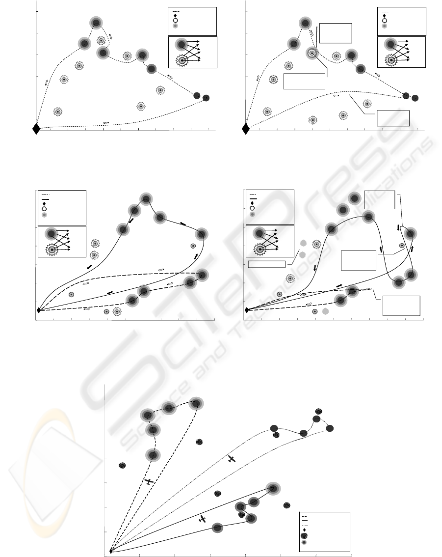
Figure 1: One UAV trajectory as determined by the planning
algorithm.
Figure 2: One UAV trajectory as determined by the
real-time control algorithm.
Figure 3: Trajectory of two UAVs as determined by the
planning algorithm.
Figure 4: During flight, updates about environmental
changes cause the real-time control algorithms on the two
UAVs to change their trajectories.
CONTROL PHASE
new
UAV samples
neighbor
region
UAV changes
path to avoid
taboo regions
2
4
6
8
10
12
5 101520253035404550
(1,1)
(2,1)
(4,1)
(5,2)
(7,3)
(6,3)
(3,1)
RANGE (miles)
ALTITUDE (miles)
CONTROL PHASE
Taboo Region
moved directly over
sampling area
UAV path
Base
Taboo pt
Sample pt
Index, priority degree(a,b)
1.0
.50
.75
CONTROL PHASE
new
UAV samples
neighbor
region
UAV changes
path to avoid
taboo regions
2
4
6
8
10
12
5 101520253035404550
(1,1)
(2,1)
(4,1)
(5,2)
(7,3)
(6,3)
(3,1)
RANGE (miles)
ALTITUDE (miles)
CONTROL PHASE
Taboo Region
moved directly over
sampling area
UAV path
Base
Taboo pt
Sample pt
Index, priority degree(a,b)
1.0
.50
.75
5 10 15 20 25 30 35 40 45 50
2
4
6
8
10
12
RANGE (miles)
PLANNING PHASE
(1,1)
(2,1)
(4,1)
(5,2)
(7,3)
(6,3)
(3,1)
ALTITUDE (miles)
UAV path
Base
Taboo pt
Sample pt
Index, priority degree(a,b)
1.0
.50
.75
5 10 15 20 25 30 35 40 45 50
2
4
6
8
10
12
RANGE (miles)
PLANNING PHASE
(1,1)
(2,1)
(4,1)
(5,2)
(7,3)
(6,3)
(3,1)
ALTITUDE (miles)
UAV path
Base
Taboo pt
Sample pt
Index, priority degree(a,b)
1.0
.50
.75
(1,1)
(2,1)
(3,1)
(4,1)
(5,2)
(6,2)
(7,2)
(9,2)
ALTITUDE (miles)
0
2
4
6
8
10
12
14
0 5 10 15 20 25 30 35 40 45 50
RANGE (miles)
PLANNING PHASE
(8,2)
UAV 1 path
Base
Taboo pt
Sample pt
Index, priority degree(a,b)
UAV 2 path
1.0
.50
.75
(1,1)
(2,1)
(3,1)
(4,1)
(5,2)
(6,2)
(7,2)
(9,2)
ALTITUDE (miles)
0
2
4
6
8
10
12
14
0 5 10 15 20 25 30 35 40 45 50
RANGE (miles)
PLANNING PHASE
(8,2)
UAV 1 path
Base
Taboo pt
Sample pt
Index, priority degree(a,b)
UAV 2 path
1.0
.50
.75
RANGE (miles)
new
new
Less dangerous
taboo region
therefore able to
fly near
UAV 2
responses to
help request.
CONTROL PHASE
0
2
4
6
8
10
12
14
0 5 10 15 20 25 30 35 40 45 50
(1,1)
(2,1)
(3,1)
(4,1)
(5,2)
(6,2)
(7,2)
(8,2)
(9,2)
UAV 1
malfunctions,
requests for help.
Old taboo regions
ALTITUDE (miles)
UAV 1 path
Base
Taboo pt
Sample pt
Index, priority degree(a,b)
UAV 2 path
1.0
.50
.75
0 5 10 15 20 25 30 35
0
5
10
15
20
25
30
35
6,1
5,1
4,1
3,1
2,1
1,1
8,2
7,1
10,2
9,2
11,3
13,3
12,3
14,3
Y Plane
PLAN PHASE
X Plane
UAV 1 path
Base
Sample pt
Index, priority degree
(a,b)
UAV 2 path
UAV 3 path
Taboo Region
0 5 10 15 20 25 30 35
0
5
10
15
20
25
30
35
6,1
5,1
4,1
3,1
2,1
1,1
8,2
7,1
10,2
9,2
11,3
13,3
12,3
14,3
Y Plane
PLAN PHASE
X Plane
UAV 1 path
Base
Sample pt
Index, priority degree
(a,b)
UAV 2 path
UAV 3 path
Taboo Region
Figure 5: Three UAV mission described in Table 1, an example of the AUP decision tree’s assignments.
FUZZY LOGIC BASED UAV ALLOCATION AND COORDINATION
17

Figure 5 provides an example of the AUP
decision tree’s assignment of three UAVs to three
paths. The highest priority locations are assigned to
UAV(1) as it has the greatest fuel capacity, i.e., 90
minutes. UAV(1) however does not have enough
fuel to handle the high priority points located at
positions six and seven and therefore UAV(2) is
assigned these points along with the second degree
high priority locations.
Table 1 provides numerical details of the tasks
depicted in Figure 5. The column labels have the
following interpretation: “Location,” the UAV
coordinates on the map; “Fly mode,” whether the
UAV sampled from its previous location to its
current position. If the UAV sampled then a “S”
was entered. “NS” was entered if sampling did not
occur. “Fuel Time” refers to how much fuel
remained by the time the UAV reached the
associated location.
6 SUMMARY
Fuzzy logic based planning and control algorithms
that allow a team of cooperating unmanned aerial
vehicles (UAVs) to make meteorological
measurements have been developed. The planning
algorithm including the fuzzy logic based
optimization algorithm for flight path determination
and the UAV path assignment algorithm are
discussed. The control algorithm also uses these
fuzzy logic algorithms, but also allows three types of
automatic cooperation between UAVs. The fuzzy
logic algorithm for automatic cooperation is
examined in detail. Methods of incorporating
environmental risk measures as well as expert
measures of UAV reliability are discussed as they
relate to both the planning and control algorithms.
Experimental results are provided. The experiments
show the algorithms’ effectiveness.
REFERENCES
Blake, L.V. 1986. Radar Range-Performance Analysis.
Boston. Artech House.
Blackman, S. and Popoli, R. 1999. Design and Analysis of
Modern Tracking Systems
, Boston, Artech House,
Chapter 11.
Russel, S.J. and Norvig, P. 2002.
Artificial Intelligence: A
Modern Approach (2nd Edition)
, Englewood Cliffs,
Prentice-Hall.
Smith, J. F., 2002a. Co-evolutionary Data Mining to
Discover Rules for Fuzzy Resource Management, In:
H. Yin, ed.,
Proceedings of the International
Conference for Intelligent Data Engineering and
Automated Learning
, August, 2002, Manchester,
Springer-Verlag, 19-24.
Smith, J. F., 2002b. Data Mining for Fuzzy Decision Tree
Structure with a Genetic Program,
In: H. Yin, ed.,
Proceedings of the International Conference for
Intelligent Data Engineering and Automated
Learning
, August 2002, Manchester, Springer-Verlag,
13-18.
Smith, J. F., 2003. Fuzzy logic resource manager: decision
tree topology, combined admissible regions and the
self-morphing property,
In: I. Kadar ed., Signal
Processing, Sensor Fusion, and Target Recognition
XII
, Vol. 5096, April 2003, Orlando, SPIE
Proceedings, 104-114.
Smith, J. F., 2004a. Fuzzy logic resource manager: real-
time adaptation and self organization, 2004,
In: I.
Kadar, ed.,
Signal Processing, Sensor Fusion, and
Target Recognition XIII
, Vol. 5429. April 2004,
Orlando, SPIE Proceedings, 77-88.
Smith, J. F., 2004b. Genetic Program Based Data Mining
for Fuzzy Decision Trees
, In: H. Yin, ed., Proceedings
of the International Conference for Intelligent Data
Engineering and Automated Learning
, August 2004,
Exeter, Springer-Verlag, 464-470.
Smith, J. F., Nguyen, T. H., 2005. Distributed autonomous
systems: resource management, planning, and control
algorithms, In: I. Kadar ed., Signal Processing, Sensor
Fusion, and Target Recognition XIV
, Vol. 5809, April,
2005, Orlando, SPIE Proceedings, 65-76.
Spears, D. and Zarzhitsky, 2005. D., Multi-Robot
Chemical Plume Tracing.
In: A. Schultz, ed. Multi-
Robot Systems: From Swarms to Intelligent
Automata,
Vol. III, May, 2005, New York, Springer,
211-221.
Tsoukalas, L., H. and Uhrig, R., E. 1997.
Fuzzy and
Neural Approaches in Engineering
, New York, John
Wiley and Sons, Chapter 5.
ICINCO 2006 - INTELLIGENT CONTROL SYSTEMS AND OPTIMIZATION
18
