
RECONFIGURABLE HARDWARE IN-THE-LOOP SIMULATIONS
FOR DIGITAL CONTROL DESIGN
Carlos Paiz, Christopher Pohl and Mario Porrmann
Heinz Nixdorf Institute, University of Paderborn
F
¨
urstenalle 11, 33102 Paderborn, Germany
Keywords:
FPGA, Hardware-in-the-Loop, digital control, reconfigurable hardware.
Abstract:
A framework to perform hardware-in-the-loop (HIL) simulations in the designflow of digital controllers, based
on Field Programmable Gate Array (FPGA) technology, is presented. The framework allows the interaction
of digital controllers, implemented on our rapid prototyping system RAPTOR2000 with a Matlab/Simulink
simulation running on a host computer. The underlying hardware and software designs supporting the interac-
tion of the digital control and the simulation are presented. The designflow of FPGA-based digital controllers
when using HIL is described and examples are given. Results from HIL simulations are presented, showing
that the acceleration of the simulation increases with the complexity of the design when the number of I/Os
stays constant.
1 INTRODUCTION
Reconfigurable hardware has been successfully used
to implement a variety of applications, ranging from
digital signal processing (Tessier and Burleson, 2001)
to digital control (Paiz et al., 2005), among others.
The key feature of this technology is its ability to per-
form computations spatially (i.e. in hardware) to in-
crease performance, while retaining much of the flex-
ibility of a software solution (i.e. reconfigurability).
Applications of digital controllers using reconfig-
urable hardware have been reported since the early
90’s. However, it is only until recently, that re-
searchers have started to explore the potentials of-
fered by this technology. This is due to the higher
computational demands of digital control systems and
the fast evolution of Field Programmable Gate Arrays
(FPGA) technology.
Among the many kinds of existent reconfigurable
architectures, we research FPGAs as implementation
platform for control algorithms. Modern FPGAs are
heterogeneous architectures, constituted by program-
mable functional blocks interconnected by a recon-
figurable network and embedded application specific
hardware, such as embedded processors, block RAM,
or multipliers. This kind of architecture allows the
implementation of complete Systems on Chip (SoC).
FPGAs have been used to implement control algo-
rithms in areas such as motor control (Carrica et al.,
2003)(Tazi et al., 1999), power electronics (Huang
et al., 2002) (Woo et al., 2005), industrial control
(Fernandes et al., 1997) (Nascimento et al., 2004),
sensor monitoring (Bhatti and Hannaford, 1997)(Her-
nandez et al., 2004), motion control (Hannan Bin
Azhar and Dimond, 2002) (Hong-Tzong et al., 2005),
among others. Some of the reported advantages of us-
ing FPGAs are acceleration, flexibility, reduced costs,
and low energy consumption.
The increasing interest in using this technology is
evident. However, the migration from traditional plat-
forms, such as DSPs or microprocessors, to recon-
figurable hardware is not a straightforward process,
since a different background is required to use this
technology. To ease the migration, high-abstraction-
level hardware description languages (HDL) are used
(e.g., DSP builder from Altera or System Genera-
tor from Xilinx), which enable non-experts in digital
hardware design to easily implement algorithms using
FPGAs.
For the design, implementation and testing of dig-
ital control systems, Hardware-in-the-Loop (HIL)
simulations are becoming an essential tool. Accord-
ing to (Isermann et al., 1999), a HIL simulation is
characterized by the operation of real components
in connection with real-time simulated components.
The simulated components are often the processes be-
39
Paiz C., Pohl C. and Porrmann M. (2006).
RECONFIGURABLE HARDWARE IN-THE-LOOP SIMULATIONS FOR DIGITAL CONTROL DESIGN.
In Proceedings of the Third International Conference on Informatics in Control, Automation and Robotics, pages 39-46
DOI: 10.5220/0001221900390046
Copyright
c
SciTePress

ing controlled and/or sensors and actuators.
The utilization of HIL simulations has been exten-
sively reported in literature. (Terwiesch et al., 1999)
have presented a HIL simulation setup based on sev-
eral commercially available boards for rail vehicle
control system integration. Their approach is based
on the acceleration of the simulated model by us-
ing several processors concurrently to achieve a real-
time simulation based on the controller timing, which
has a sampling period of 30µs. Similar approaches
have been described in (Shiakolas and Piyabongkarn,
2003), (Antonelli et al., 2001), (Grono, 2001), (Lian
and Lehn, 2005) and (Crosbie et al., 2004) where a
simulated process is accelerated in order to couple it
in real-time with the control system, which is running
on the final implementation platform.
A different approach was presented in (Hafner
et al., 2002), (Isermann and M ¨uller, 2003), (Lin
et al., 2006) and (Yue et al., 2005). Real parts of the
system being controlled were actually used in the sim-
ulation loop. This method was said to bring more ac-
curacy to the simulation, making the design process
shorter for that specific application. However, since
the setup was application specific, it was not possible
to use it for other designs.
In all previously mentioned publications software-
based architectures (e.g., DSPs or microcontrollers)
were used as the final implementation platform and
therefore are not suitable for an FPGA-based con-
trol designflow. Different groups have been work-
ing on acceleration and debug environments for
FPGA designs. In (Deppe et al., 2004), a frame-
work for the design of control algorithms for mecha-
tronic systems, including HIL simulations, was pre-
sented. The design and implementation of linear,
time-invariant (LTI) control systems on FPGA tech-
nology was described using a self-developed soft-
ware called Computer-Aided Mechatronics Labora-
tory (CAMeL), as design environment.
There are commercially available FPGA-based
prototyping boards which can perform HIL simula-
tions. In (Cantle et al., 2002) a HIL system, DIME
from Nallatech, was presented. This board is con-
nected to the host PC via the PCI bus. Their approach
is not universal and requires the user to develop on the
DIME board. Our approach is platform independent
and can be adapted to any existing prototyping envi-
ronment with a reasonably fast communication link.
Our current implementation is based on the mod-
ular rapid prototyping system RAPTOR2000, which
is connected to the host computer via the PCI bus,
but it is universally adaptable to other platforms. Our
framework enables the utilization of RAPTOR2000
for HIL simulation under Matlab/Simulink. Simu-
lations are coupled in real-time with the prototyped
controller by controlling its system clock. In that way,
the digital controller can be accurately tested, without
the need of accelerating the simulated process, yet the
HIL simulation experiences a noticeable acceleration
in comparison to a full software simulation.
In the following subsection various terms used in
this paper are introduced. Section two describes
in detail the framework used for Hardware-in-the-
Loop simulations, starting from the underlying hard-
ware platform and supporting hardware blocks, fol-
lowed by the software to integrate the digital design
with a simulation running under Matlab/Simulink.
The utilized tool flow is also described in this sec-
tion. In section three the design flow of digital con-
trollers that utilizes our Hardware-in-the-Loop frame-
work is shown and three examples with the corre-
sponding performance data are presented. Finally, in
section four conclusions are drawn and future work is
sketched.
1.1 Definitions
In the following paragraphs some of the terms used in
this paper are introduced.
Sample Rate: from the point of view of a digital
hardware designer, this is the frequency at which a
given input/output port is driven/updated.
Single-Rate Design: is a design where all elements
share a common clock (all input/output ports share
the same sample rate and there is no internal up/down
sampling). This is the simplest clock scheme.
Multi-Rate Design: a design is multi-rate if it
has signals running at different clock frequencies. A
multi-rate design can either be driven by a single
clock (in which case all other frequencies are derived
from it) or by many clocks.
Periodic Design: a design is periodic if its latency
is known and stays constant. Examples are digital fil-
ters or classical control algorithms (e.g., PID).
Aperiodic Design: a design is aperiodic if its la-
tency varies depending on the input data. This varia-
tion might happen because an adaptation to different
inputs or operative regions. However, the processing
time is bounded to a maximum (e.g., the latency is
known to be never greater than the required sampling
period). Designs that fall in this category are soft-
processors and adaptive control schemes (e.g., multi-
model based control).
DUT: this is the acronym for Design Under Test. It
refers to the algorithm being developed. This is the
part of the simulation, which is implemented in re-
configurable hardware. The DUT is implemented on
an FPGA module of our RAPTOR2000 (see section
2.1.1).
DUT Clock: the clock frequency used by the DUT.
This clock frequency may be different (lower) from
that of the hardware part of the HIL framework (Hard-
ware Wrapper and Synchronizer, cf. section 2.1.4).
ICINCO 2006 - SIGNAL PROCESSING, SYSTEMS MODELING AND CONTROL
40

System Clock: this is the maximum clock fre-
quency (used by the Hardware Wrapper and the Syn-
chronizer, see 2.1.3).
2 SIMULATION FRAMEWORK
The Hardware-in-the-Loop simulation framework
consists of hardware and software interfaces, which
enable the interaction of the DUT with Mat-
lab/Simulink. These interfaces are described in the
following sections.
2.1 Hardware
In the following section our rapid prototyping sys-
tem and the hardware designs, which support our HIL
framework, are described.
2.1.1 RAPTOR2000
The underlying hardware platform is the RAP-
TOR2000 system, a rapid prototyping environment,
which has been developed at our department. The
board itself has been used in many research projects,
e.g., (Pohl et al., 2004),(Kalte et al., 2000), (Kalte
et al., 2002) and therefore only the communication
structure is described.
The interface between the RAPTOR2000 FPGA
module(s) on the one hand and the PCI bus on the
other hand is done by a PLX9054 chip, which is a bus
master compatible PCI bridge (see fig. 1). This bridge
translates the PCI protocol to a 32 bit local bus on the
board and back. FPGA designs that have to access
host data have to implement a local bus (LB) inter-
face. The LB interface is very small (less than 1%
slice usage on a Xilinx XC2V3000 FPGA) and easy
to use. All communication between FPGA and host is
processed by this interface, so its transfer rate is criti-
cal for the resulting simulation speed. Measurements
show maximum rates of 25 MByte/s in PIO mode and
95 MByte/s in DMA mode.
DUT
MATLAB
synchronizer
LB interface
S-Function
raptorlib.dll
PLXapi.dll
PCI bridge
(PLX9054)
user I/O
FPGA
Figure 1: Schematics of the Hardware-in-the-Loop simula-
tion framework.
2.1.2 Clock Management
In this section we describe the clock management,
which is a critical part of the HIL simulation. In or-
der to generate a real-time simulation (from the point
of view of the simulation timing), it is necessary to
precisely control the number of clock cycles during
which the DUT must run.
All memory elements (registers, latches, block
RAM, etc.) have two clock related inputs: the clock
input and the clock enable input. In single-rate de-
signs the clock enable input is usually set to one,
which means that the register operation depends on
the clock (usually the rising edge of the clock) only.
In our case it is used to control the hardware simula-
tion; while the system clock keeps running, the clock
enable signal is set to zero and therefore all mem-
ory elements keep their current state. This is a better
option than using clock-gating, since it avoids hav-
ing delays in the clock path and the problems derived
from them (e.g., additional delays in the clock tree).
In effect, this is the same as halting the DUT-clock(s)
and therefore allows cycle accurate simulation (like
debug-stepping) of the behaviour of the circuit, while
the timing behaviour is not correctly simulated. Both
clock gating and clock enable generate implicit multi-
cycle paths, which do not render the normal operation
mode.
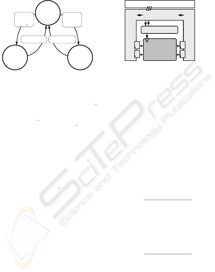
2.1.3 Synchronizer
In order to coordinate a simulation with a DUT, a Fi-
nite State Machine (FSM), the Synchronizer, has been
implemented as a dedicated hardware block. The
Synchronizer enables the DUT clocks (see section
2.1.2) after a request from a Matlab/Simulink simu-
lation. Therefore, if a design is to be simulated us-
ing our HIL framework, it needs to have a CE port
associated with its clock. The states diagram of the
Synchronizer is depicted in figure 2.
The Synchronizer controls a given DUT in two pos-
sible modes: periodic and aperiodic (see section 1.1).
Before explaining these operative modes, the ports of
the Synchronizer are introduced. The current version
of the Synchronizer has four input ports and four out-
put ports to interact with the simulation and the DUT.
When the simulation sends a non-zero value to
the running
time port, the Synchronizer enters the
periodic mode. The DUT is then enabled during
the requested time, keeping the hand-shaking signal
DUT
busy enabled and ignoring the DUT ready port.
The design updates its output ports, which are read
and stored by the Synchronizer and sent to the host
computer, where the simulation reads and propagates
them to the other blocks (e.g. a plant model) in the
simulation.
RECONFIGURABLE HARDWARE IN-THE-LOOP SIMULATIONS FOR DIGITAL CONTROL DESIGN
41
Start_running=1
and
DUT_ready=1
and
Run_till
0
Clock_cycles>=Run_till
DUT_ready=1 or
Clock_cycles>= Time_limit
Start_running=1
and
DUT_ready=1
and
Run_till = 0
DUT_enable=0
DUT_busy=0
New_data=0
Time_exceeded=0
Idle
Periodic
DUT_enable=1
DUT_busy=1
New_data=1*
Time_exceeded=0**
DUT_enable=1
DUT_busy=1
New_data=1*
Time_exceeded=0**
Aperiodic
Figure 2: Synchronizer state machine (* This signal is en-
abled during one System clock cycle, ** Not used in this
mode, *** Set to one if a time overflow occurs).
If the simulation sends a zero to the running
-
time port, the Synchronizer enters the aperiodic mode
and waits until the DUT sends a hand-shaking sig-
nal through the DUT
ready port to disable it. As in
the periodic mode, the output port DUT
busy is set
to high, in order to prevent that the simulation sends
new values while the DUT is busy. Although this case
might happen very rarely (cf. section 2.1.5), this sig-
nal avoids to loose the synchronization between the
DUT and the simulation.
The Synchronizer also detects whether there is a
discrepancy between the given sampling period and
the time required by the DUT to complete a cycle.
This happens if its latency is greater than the sam-
pled period reported by the simulation. In this case
the DUT is disabled and a warning signal is sent to
the simulation through the time
exceeded port. The
simulation can then react to this exception.
2.1.4 Hardware Wrapper
Both the Synchronizer and the DUT, are embedded
in a hardware wrapper, as depicted in figure 3. The
Wrapper provides specialized hardware for interfac-
ing the Synchronizer and the DUT with the Matlab
simulation running on the host computer through the
PCI bus (see section 2.1.1). In order to embed the
DUT into the Wrapper, the bus interface is adapted to
the input and output ports of the DUT. This process is
done automatically as described in section 2.2.
The Wrapper enables reading and writing data from
and to the input/output ports from the simulation.
There are two methods to realize these operations: us-
ing a registers bank and using a FIFO memory. In
control applications, one often has feedback loops,
which means, that the output(s) (or some function of
it) has to be fed back to the input(s) without delay.
This implies the use of registers instead of FIFOs for
Host PC with Simulink Simulation
BUS Interface to Host
input memories (registers/FIFOs)
output memories (registers/FIFOs)
Synchronizer FSM
System Generator /
VHDL-
DUT
Figure 3: Synchronizer embedded in bus interface.
communication, which is, however, the slowest pos-
sible way of communication because only one input
and output can be write/read per cycle; the amount of
data to be transferred is rather small, so that the com-
munication overhead is high. For multi-inputs multi-
outputs (MIMO) systems, this process can be acceler-
ated by utilizing DMA transfers, which has to be im-
plemented in the future. A further increase of commu-
nication throughput can be achieved by implementing
FIFOs instead of a register bank. This is, however,
no used for control applications with a feedback loop
and is therefore postponed to future work.
2.1.5 Hardware Performance
There are several pre- and post-processing steps
needed to simulate one (or several) DUT cycles (cf.
section 2.1.3 and section 2.3). Taking into account
these actions a theoretical maximum for the simula-
tion frequency is
F
sim
=
1
T
update
+ T
run
+ T
fetch
(1)
where T
update
is the time required to update the mem-
ories at the input of the DUT, T
run
is equivalent to the
time needed by the DUT to produce a new output, and
T
fetch
is the time for retrieving the data from the out-
put memories. If T
DU T
≈ T
P CI
(period of the DUT
clock and Period of the PCI clock correspondingly),
for a filter running at F
DU T
= 50M Hz
F
sim
≤
R
T
W
Bus
∗ (1 + N
I
+ N
O
)
(2)
is a good approximation. Here, N
I
and N
O
are the
numbers of input and output ports of the DUT, W
Bus
is the width of the PCI bus (PCI: 32 bit), and R
T
is
the transfer rate, which can be achieved in the current
mode (PIO or DMA). An example for an application
with a lower frequency might be a controller for some
mechanical system, where the control update rate is
ICINCO 2006 - SIGNAL PROCESSING, SYSTEMS MODELING AND CONTROL
42
in the magnitude of kHz, so T
DU T
≫ T
P CI
. Here
F
sim
≤ (T
DU T
+
W
Bus
R
T
∗ (1 + N
I
+ N
O
))
−1
(3)
is a reasonable approximation. Software issues, such
as calculation of the test vectors (Simulink model),
are not included in this consideration and will influ-
ence the results according to their complexity. On the
software side, PIO and DMA transfers can be initi-
ated via simple library functions, which have been in-
tegrated into an S-Function block (for details cf. 2.3).
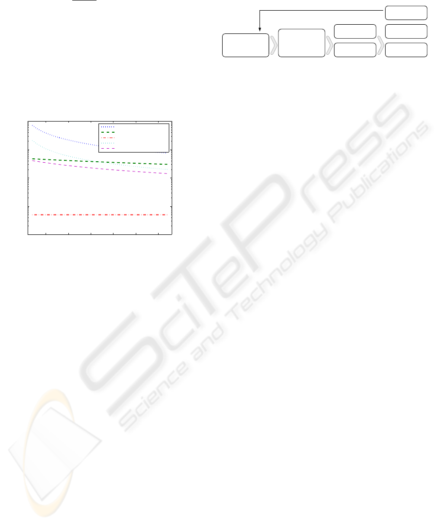
In figure 4, the theoretical maximum for the simula-
5 10 15 20 25 30
10
3
10
4
10
5
10
6
10
7
Number of input and output ports
Maximum simulation frequency
DMA mode, Tdut = 2e−8 s
DMA mode, Tdut = 2e−6 s
DMA mode, Tdut = 2e−4 s
PIO mode, Tdut = 2e−8 s
PIO mode, Tdut = 2e−6 s
Figure 4: Theoretical maximum for simulation perfor-
mance.
tion frequency (cf. equation 2) is given. The points
indicate real measurements made with our examples
(see section 3). The actual values are a lot lower than
the theoretical maximum, because a lot of calcula-
tions have to be conducted in software. This is the
software model on the one hand and the preprocessing
and postprocessing of data for the hardware imple-
mentation on the other hand. For a detailed descrip-
tion of the necessary translation steps for the hard-
ware, see section 2.3.
2.2 Hardware Integration
The Hardware Wrapper described in the previous sec-
tion stays the same between different hardware im-
plementations, except for the embedded DUT and
the corresponding bus interface. To simplify and ac-
celerate the process of generating the wrapper and,
there upon, the hardware, a JAVA based application
(vhdl2mex) was developed, which is embedded in the
toolflow as depicted in figure 5. This Software reads
the top level of the VHDL design and identifies the
top level entity, port attributes and generics. These
are displayed in a graphical user interface, where the
user can introduce certain changes to the default val-
ues (e.g., not reading an output, setting an input to a
constant and so on). The port data rates have to be
defined here, too, which is a topic to be processed au-
tomatically in future.
MATLAB/Simulink
NGD file +
VHDL entity
vhdl2mex:
VHDL wrapper + S-
Function parameters
ISE: bit file
RAPTOR2000
r2ksim: config
simulink block
HW/SW
Co-Simulation
design entry wrapper generation
HW generation
Simulink configuration
Data Logging
HW Acceleration
Figure 5: Toolflow for HIL simulations.
In addition to the hardware, vhdl2mex generates a
configuration string for a MATLAB S-Function (cf.
2.3) containing addresses and data rates of input and
output ports. This HIL flow, as depicted in figure 5,
integrates seamlessly into available FPGA flows, be-
cause no vendor specific information is added.
2.3 MATLAB Integration
MATLAB provides a generic interface for integrat-
ing user defined software into the Simulink simulation
process, the so called S-Function. The basic simula-
tion steps and their pendants for HIL simulation with
RAPTOR2000 are displayed in figure 6(a) and 6(b).
Basically, the mdlStart() function is used for the hard-
ware initialization (download of the bitstream, con-
figuration of the synchronizer). If mdlStart() suc-
ceeds, the simulation loop sequentially calls mdlUp-
date() and mdlOutputs(). In mdlOutputs() the data in
the hardware output registers is read and propagated
to the outputs of the Simulink block. In mdlUpdate()
data from the input ports of the simulink blocks is
sent to the hardware input registers, respectively. md-
lUpdate() also starts the synchronizer to activate the
DUTClock for one clock cycle. In addition to these
communication steps, several translation steps from
the Simulink floating point datatypes to the hardware
fix point data types have to be accomplished inside
the S-Function. The parameters for this translation as
well as information on the hardware configuration are
given in a configuration string provided by vhdl2mex.
The current implementation of the S-Function in-
terface is to be considered as a proof of concept and
there is room for a lot of improvements. These im-
provements, in addition to the use of faster data trans-
fers (DMA) will certainly improve the simulation per-
formance.
3 THE DESIGNFLOW
The proposed designflow, including HIL simulations,
is completely based on Matlab/Simulink. This high-
level tool has become an essential development envi-
ronments in control engineering. Hence, it is eligi-
RECONFIGURABLE HARDWARE IN-THE-LOOP SIMULATIONS FOR DIGITAL CONTROL DESIGN
43
Initialize Model
mdlCheckParameters
mdlInitializeSizes
mdlInitializeSampleTimes
mdlStart
Calculate outputs
mdlOutputs
Update discrete states
mdlUpdate
End Simulation
mdlTerminate
simulation loop
(a) Simulink Simulation
steps
download bitstream
fetch outputs
write inputs
run n cycles
simulation loop
Initialize Synchronizer
Initialize DUT
(b) r2ksim steps
Figure 6: Simplified simulation flow diagram.
ble to use it for the development of digital controllers
to be implemented on reconfigurable hardware. The
designflow presented in this section uses the System
Generator from Xilinx. However, the HIL frame-
work is not platform dependent. It is also possible
to use it with toolboxes from other vendors (e.g., DSP
Builder from Altera or Symplify DSP from Synplic-
ity) or with custom VHDL designs.
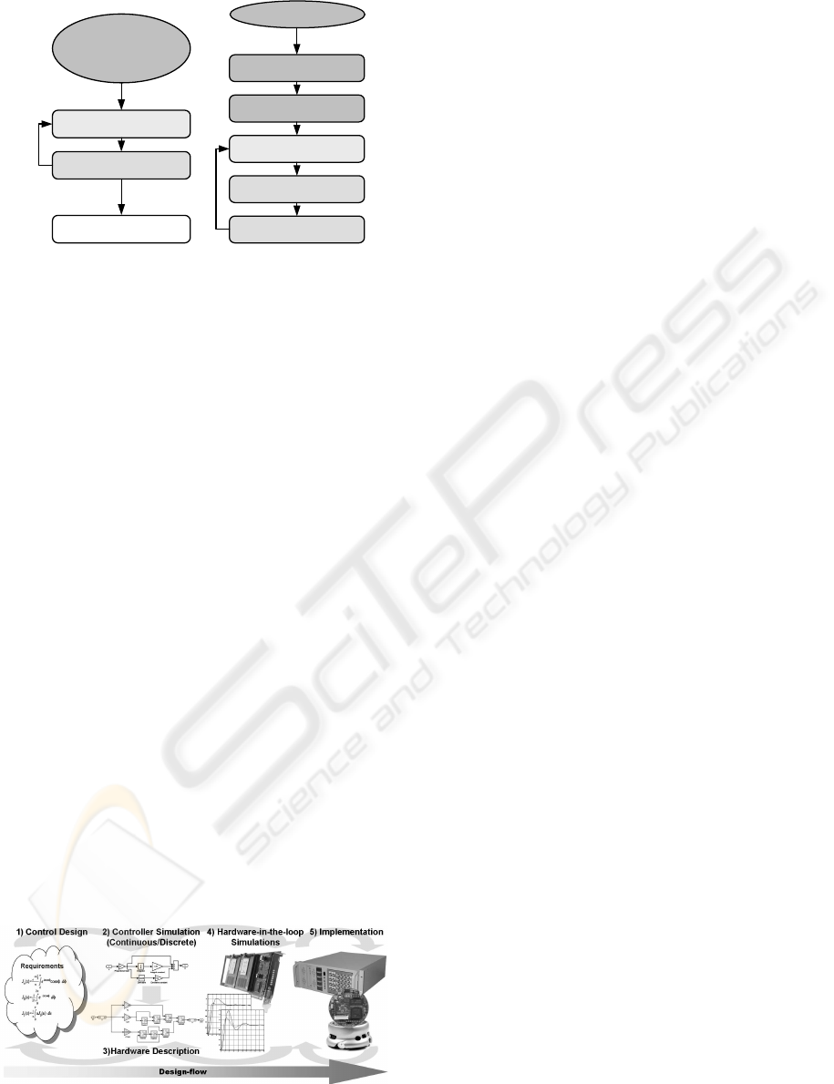
The designflow of digital control algorithms can be
divided roughly in five steps, as depicted in figure 7.
In the first step, the requirements of the controller are
defined. A better understanding of the plant should
be gained in this step. A first mathematical descrip-
tion of the controller is then derived, either by a time-
continuous representation (e.g., described by differ-
ential equations) or by a time-discrete representation
(e.g., described by difference equations).
The second step is the simulation of the controller
together with a model of the process. The accuracy of
this model has a direct impact on the design. There
are other aspects, which should be modeled accu-
rately, such as the dynamics of sensors and actuators.
After the designer is satisfied with the performance of
the controller, a third step is its translation to a hard-
ware description language. For this purpose, we use
Figure 7: The Designflow. After appropriate conducting
HIL simulations, the DUT can be directly implemented.
the System Generator from Xilinx.
The System Generator has been conceived as an
extension of Simulink (i.e., a toolbox). Similarly
to the Real Time Workshop and Embedded Coder,
which generate C-code for diverse microprocessors
and DSPs, the System Generator automatically gener-
ates structural hardware descriptions (netlists) from a
very high-level representation, which can be mapped
onto an FPGA later. The realization of a digital con-
trol algorithm with the System Generator is done in
the following phases: modeling, simulation, resource
estimation, and hardware description, as described,
e.g., in (Paiz et al., 2005). These phases are under-
taken in step three of the design flow, as depicted in
figure 7.
In step four, a netlist (a textual representation of
the synthesized hardware) is automatically generated.
This netlist is integrated into our HIL framework, as
described in section 2.2. A configuration bitstream is
generated using the ISE from Xilinx. An automati-
cally adapted S-Function replaces the System Gener-
ator design and the HIL simulations are carried out
without further ado of the user.
The simulations are performed as usual. However,
the designer can now realize whether the controller,
running on an FPGA module of the RAPTOR2000,
actually works as expected. In this stage more inten-
sive tests can be conducted. Since the structure of the
controller has already been designed and tested, the
next step is an intensive test of its parameters or its
response to different operative regions. This process
is greatly accelerated by HIL simulations, besides the
enhanced reliability of this kind of simulations.
The final step corresponds to the test of the con-
troller when interacting with the real plant. As shown
in figure 7, these steps are iterative. It is often neces-
sary to go one or two steps back. However, the gap
between step three and five is reduced by including
HIL simulations.
In the following subsections, some examples are
presented as a proof of concept. The results of the
simulations are compared and discussed in the last
section.
3.1 PID-based Speed Control
As a first example, a PID algorithm for controlling the
speed of a DC-motor is presented. The PID algorithm
is still one of the most widely used designs in indus-
try. The control task consists of regulating the speed
of a DC motor by manipulating its input voltage. A
state-space model of the DC motor is used to test the
controller. A classical parallel PID is designed.
The system has one input and one output, the sam-
pling frequency was set to 1KHz. The simulated
time was 10 seconds. Software simulation lasted
ICINCO 2006 - SIGNAL PROCESSING, SYSTEMS MODELING AND CONTROL
44

15.9248 seconds (628 Hz). Using our HIL frame-
work, the simulation lasted 12.445 seconds (996 Hz).
The speedup was relatively small, due to the low com-
plexity of the design, which had an equivalent gate
count of 5,722. However, it could be verified that the
prototyped design worked as required during the HIL
simulations, as well as when tested with the real plant.
3.2 Inverted Pendulum
The inverted pendulum is a classical problem in con-
trol theory; it has been used in literature as an exam-
ple of a well-understood yet non-trivial system to test
control algorithms. In (Paiz et al., 2005), this system
was used to exemplify the utilization of partial and dy-
namic reconfiguration of an FPGA to efficiently im-
plement a multi-controller system. The controller for
the pendulum was split in two; one to swing up the
pendulum and the other one to balance it, loading only
one controller at the time on the FPGA.
To test our HIL framework, the balancing control
was used. A state-space model of the pendulum at-
tached to a motor was used in the simulations. The
controller had an equivalent gate count of 209,218.
The system has two inputs (the angle of the pendu-
lum and the position of the motor) and one output (the
new position of the motor). The sampling period of
the controller was 10 µs (10 KHz). Five seconds of
simulation using the System Generator blocks lasted
63.4769 seconds (787 Hz), while using the proposed
HIL framework the simulation time was reduced to
3.1334 seconds (9512 Hz). This represents a speed
up of 19.15. The prototyped controller worked just as
well as the simulated design and also the tests on the
real system have been successful.
3.3 Recursive IIR Filter
The third example is a hardware implementation of
a Chebyshev II Filter. This implementation is rather
special because of the internal feedback loop, which
enables the emulation of multiple filter blocks through
oversampling. The testbench in this case consist
of some scopes and of a ”From Workspace” block,
which feeds the test data from a Matlab array to the
filter. Considering software effort, this is probably the
smallest meaningful testbench, therefore the measure-
ments in this case contain the smallest possible soft-
ware overhead. Our example has one input and two
outputs and a sample frequency of 25 MHz, the sim-
ulated time was 0.001 second. Software Simulation
(System Generator model) took 56.2787 seconds (444
Hz), while the HIL simulation took 12.5443 seconds
(3985 Hz).
This results show the great potential of using HIL
simulation to speed up the design flow of FPGA-
based control system.
4 CONCLUSION AND FUTURE
WORK
In this paper a platform independent and extendable
framework for FPGA-based HIL simulations under
MATLAB/Simulink has been presented. The struc-
ture and operation mode of hardware and software
have been shown and examples have been presented.
The results show that our system is capable of ac-
celerating simulations within the MATLAB/Simulink
environment and can be used as a cycle accurate de-
bugger for designs with algebraic loops. Future work
concentrates on further automation of the hardware
generation process and on extending the approach
into new areas. These comprise of softcore debug-
ging (software in the loop) and data logging features
for rapid control design. Another important issue is to
improve the acceleration abilities of our FPGA in the
loop approach. Enabling HIL simulations of design
including partial and dynamic reconfiguration for the
implementation of adaptive control algorithms is also
planned as future work.
ACKNOWLEDGEMENTS
This work was supported by the Collaborative Re-
search Center 614 - Self-Optimizing Concepts and
Structures in Mechanical Engineering - University
of Paderborn, and was published on its behalf and
funded by the Deutsche Forschungsgemeinschaft and
the Mexican National Council of Science and Tech-
nology (CONACyT).
REFERENCES
Antonelli, G., Chiaverini, S., Finotello, R., and Schiavon, R.
(2001). Real-time path planning and obstacle avoid-
ance for rais: An autonomous underwater vehicle. In
IEEE Journal Of Oceanic Engineering, volume 26,
pages 216–227. IEEE.
Bhatti, P. and Hannaford, B. (1997). Single chip velocity
measurement system for incremental optical encoders.
In 83-105, editor, IEEE Transactions on Control Sys-
tems Technology.
Cantle, A., Devlin, M., and Lord, E.and Chamberlain, R.
(2002). High frame rate low latency hardware-in-the-
loop image generation. White paper, Nallatech Ltd,
10-14 Market Street, Kilsyth, Glasgow, Scotland, G65
0BD.
Carrica, D., Funes, M., and Gonzalez, S. (2003).
Novel stepper motor controller based on fpga hard-
ware implementation. In IEEE/ASME Transac-
tions On Mechatronics, volume 8, pages 120–124.
IEEE/ASME.
RECONFIGURABLE HARDWARE IN-THE-LOOP SIMULATIONS FOR DIGITAL CONTROL DESIGN
45

Crosbie, R., Zenor, J., Bednar, R., and Word, D. (2004).
High-speed, scalable, real-time simulation using dsp
arrays. In Proceedings of the 18th Workshop on Par-
allel and Distributed Simulation (PADS04), pages 52–
59. IEEE Computer Society.
Deppe, M., Zanella, M., Robrecht, M., and Hardt, W.
(2004). Rapid prototyping of real-time control laws
for complex mechatronic systems a case study. In The
Journal of Systems and Software, volume 70, pages
263–274.
Fernandes, J. M., Adamski, M., and Proenca, A. J. (1997).
VHDL generation from hierarchical petri net specifi-
cations of parallel controllers. In IEE Proceedings-
E Computers and Digital Techniques, volume 144,
pages 127–137.
Grono, A. J. (2001). Synchronizing generator with HITL
simulations. In IEEE Computer Applications in
Power, pages 43–46. IEEE.
Hafner, M., Jost, O., and Isermann, R. (2002). Mechatronic
design approach for engine management systems. In
Mechatrnoics, volume 12, page 10351046. Elsevier.
Hannan Bin Azhar, M. A. and Dimond, K. R. (2002). De-
sign of an fpga based adaptive neural controller for
intelligent robot navigation. In Euromicro Symposium
on Digital System Design, volume 00, pages 283–295.
Hernandez, A., Urena, J., Garcia, J., Mazo, M., Hernanz,
D., Derutin, J., and Serot, J. (2004). Ultrasonic rang-
ing sensor using simultaneous emissions from differ-
ent transducers. In IEEE Transactions On Ultrasonics,
Ferroelectrics, And Frequency Control, volume 51,
pages 1660–1670.
Hong-Tzong, Y., Ming-Tzong, L., Yao-Ter, C., and Kuo-
Chin, Y. (2005). Design and implementation of
real-time nurbs interpolator using a FPGA-based mo-
tion controller. In IEEE International Conference on
Mechatronics (ICM2005), pages 56–61, Taipei, Tai-
wan.
Huang, S. J., Yang, T., and Huang, J. (2002). Fpga real-
ization of wavelet transform for detection of electric
power system disturbances. In IEEE Transactions On
Power Delivery, volume 17, pages 388–394.
Isermann, R. and M ¨uller, N. (2003). Design of computer
controlled combustion engines. In Mechatrnoics, vol-
ume 13, page 10671089. Elsevier.
Isermann, R., Schaffnit, J., and Sinsel, J. (1999). Hardware-
in-the-loop simulation for the design and testing of
engine-control systems. In Control Engineering Prac-
tice, volume 7, pages 643–653. Elsevier.
Kalte, H., Porrmann, M., and R
¨
uckert, U. (2000). Us-
ing a dynamically reconfigurable system to accel-
erate octree based 3d graphics. In Proceedings
of the International Conference on Parallel and
Distributed Processing Techniques and Applications
(PDPTA2000), volume 5, pages 2819–2824, Monte
Carlo Resort, Las Vegas, Nevada, USA.
Kalte, H., Porrmann, M., and R
¨
uckert, U. (2002). A pro-
totyping platform for dynamically reconfigurable sys-
tem on chip designs. In Proceedings of the IEEE
Workshop Heterogeneous reconfigurable Systems on
Chip (SoC), Hamburg, Germany.
Lian, K. L. and Lehn, P. W. (2005). Real-time simulation
of voltage source converters based on time average
method. In IEEE Transactions On Power Systems,
volume 20, pages 110–118. IEEE.
Lin, C. F., Tseng, C., and Tseng, T. (2006). A hardware-
in-the-loop dynamics simulator for motorcycle rapid
controller prototyping. In Control Engineering Prac-
tice. Elsevier.
Nascimento, P. S. B., Pand Maciel, P. R. M., Lima, M. E.,
Sant’ana, R. E., and Filho, A. G. S. (2004). A par-
tial reconfigurable architecture for controllers based
on petri nets. In SBCCI ’04: Proceedings of the 17th
symposium on Integrated circuits and system design,
pages 16–21, New York, NY, USA. ACM Press.
Paiz, C., Kettelhoit, B., Klassen, A., and Porrmann, M.
(2005). Dynamically reconfigurable hardware for dig-
ital controllers in mechatronic systems. In IEEE In-
ternational Conference on Mechatronics (ICM2005),
Taipei, Taiwan.
Pohl, C., Franzmeier, M., Porrmann, M., and R
¨
uckert,
U. (2004). gnbx - reconfigurable hardware accel-
eration of self-organizing maps. In Proceedings of
the IEEE International Conference on Field Program-
mable Technology (FPT’04), pages 97–104, Brisbane,
Australia.
Shiakolas, P. and Piyabongkarn, D. (2003). Development of
a real-time digital control system with a hardware-in-
the-loop magnetic levitation device for reinforcement
of controls education. In Education, IEEE Transac-
tions on, volume 46, pages 50–60. IEEE.
Tazi, K., Monmasson, E., and Louis, J. P. (1999). Descrip-
tion of an entirely reconfigurable architecture dedi-
cated to the current vector control of a set of ac ma-
chines. In IEEE International Conference on Indus-
trial Electronics, Control, and Instrumentation, vol-
ume 3, pages 1415–1420.
Terwiesch, P., Keller, T., and Scheiben, E. (1999). Rail ve-
hicle control system integration testing using digital
hardware-in-the-loop simulation. In Transactions On
Control Systems Technology, volume 7, pages 352–
362. IEEE.
Tessier, R. and Burleson, W. (2001). Reconfigurable com-
puting for digital signal processing: A survey. In Jour-
nal of VLSI Signal Processing, volume 28, pages 7–
27. Elsevier.
Woo, W., Miller, M., and Kenney, J. S. (2005). A hybrid
digital RF envelope predistortion linearization system
for power amplifiers. In IEEE Transactions On Mi-
crowave Theory And Techniques, volume 53, pages
229–237.
Yue, X., Vilathgamuwa, D. M., and Tseng, K. (2005). Ro-
bust adaptive control of a three-axis motion simulator
with state observers. In IEEE/ASME Transactions On
Mechatronics, volume 10, pages 437–448. IEEE.
ICINCO 2006 - SIGNAL PROCESSING, SYSTEMS MODELING AND CONTROL
46
