
Smart Sensor Networking with ZigBee and Internet
Miroslav Sveda and Roman Trchalik
Brno University of Technology, Faculty of Information Technology,
Bozetechova 2, 61266 Brno, Czech Republic
Abstract. This paper deals with sensor networking based on ZigBee and Inter-
net using IEEE 1451 smart transducer interface architecture. The contribution
begins with introduction to the IEEE 1451 smart transducer - network interface
for sensors and actuators as an emerging, standard-based networking frame-
work. Next part of the paper reviews some concepts of ZigBee architecture
aimed at connecting wireless sensors and actuators through ZigBee to Intranets
or Internet. The kernel of the paper deals with design of a software architecture
stemming from technical standards or standard proposals. This paper focuses
namely on design of software architectures of communication interconnecting
devices in between ZigBee and Internet.
1 Introduction
A framework represents a set of constraints on components and their interaction, and
a set of benefits that derive from those constraints [5]. For the embedded, computer-
based systems domain, components can be any kind of hardware/software building
blocks. Current industry is migrating away from proprietary hardware and software
platforms in favor of open and standardized approaches. Internet technologies based
on Java, WWW, TCP/IP, and Ethernet are rapidly becoming the platforms of choice
for building next generation distributed measurement and control systems. The
framework, which can support the current trend, stems from the IEEE 1451 smart
transducer interface architecture that enables to unify not only interconnecting intelli-
gent sensors with various wired and wireless fieldbuses but also direct coupling to the
Ethernet-based Intranets. Intelligent sensors supported by proper networking means
can provide not only accuracy, adaptability, reliability or recalibration, but also ad-
vanced and efficient information processing using data fusion and integration.
2 IEEE 1451 Family of Smart Transducer Interface Standards
An industry-wide, open IEEE 1451 smart transducer interface standards provide
common interfaces between sensors/actuators and instruments, microprocessors or
networks. That family consists of standards for analog, digital and wireless interfaces
that include namely (i) a smart transducer information model, IEEE 1451.1, called
Sveda M. and Trchalik R. (2006).
Smart Sensor Networking with ZigBee and Internet.
In Proceedings of the 2nd International Workshop on Artificial Neural Networks and Intelligent Information Processing, pages 64-71
DOI: 10.5220/0001222300640071
Copyright
c
SciTePress

Network Capable Application Processor (NCAP) [1], targeting software-based, net-
work independent, transducer application environments, (ii) and a standard digital
interface and communication protocol, IEEE 1451.2 [2], for accessing the transducer
via a microprocessor modeled by the NCAP. The next two standards, IEEE 1451.3
and 1451.4, extend the possible single-attached configurations to distributed mul-
tidrop buses, and to mixed-mode, i.e. analog + digital communication enabling also
analog transducers. The last two discussed proposals, IEEE 1451.5 and 1451.0 de-
scribe wireless communication protocols and drive harmonization of individual stan-
dards of the 1451 family [3].
2.1 IEEE 1451.1 NCAP
The 1451.1 software architecture provides three models of the transducer device
environment: (i) an object model of a network capable application processor (NCAP),
which is the object-oriented embodiment of a smart networked de-vice; (ii) a data
model, which specifies information encoding rules for transmitting information across
both local and remote object interfaces; and (iii) network communication model,
which supports client/server and publishers/subscribers paradigms for communicating
information between NCAPs. The standard defines a network and transducer hard-
ware neutral environment in which a concrete sensor/actuator application can be
developed.
The object model definition encompasses a set of object classes, attributes, meth-
ods, and behaviors that specify a transducer and a network environment to which it
may connect. This model uses block and base classes offering pat-terns for one
Physical Block, one or more Transducer Blocks, Function Blocks, and Network
Blocks. Each block class may include specific base classes from the model. The base
classes include Parameters, Actions, Events, and Files, and provide component
classes.
Block classes form the major blocks of functionality that can be plugged into an
abstract card-cage to create various types of devices. One Physical Block is manda-
tory as it defines the card-cage and abstracts the hardware and software resources that
are used by the device. All other blocks and component base classes can be refer-
enced from the Physical Block.
The Physical Block representing the card-cage contains all the logical hardware and
software resources in the model. These resources determine the basic characteristics
of the device being assembled. Information contained in the Physical Block as attrib-
utes include the manufacturer’s identification, serial number, hardware and software
revision information, and more importantly, data structures that provide a repository
for other class components. As previously mentioned, the Physical Block is the logi-
cal container for all components in the device model; therefore, it must have access to
and be able to locate all available resources instantiated by the device. The data struc-
tures provided by the Physical Block house pointers (Instance_ID) to these compo-
nents and, in that way, offer easy indirect access to them. To communicate to a device
or a device object across the network when a remote NCAP requests an attribute from
the Physical Block, that Physical Block has to resolve address queries from the net-
work. For this purpose a hierarchical naming/addressing scheme is used based on
65

unique Tags, i.e. ASCII descriptions of the block or component names, which can be
concatenated together to form fully qualified addresses. The Physical Block is the
centralized logical connector or backplane that the other blocks plug into. Therefore,
the Physical Block must provide a Locate method to find other components in the
system.
The Transducer Block abstracts all the capabilities of each transducer that is physi-
cally connected to the NCAP I/O system. During the device configuration phase, the
description is read from the hardware device what kind of sensors and actuators are
connected to the system. This information is used by the Physical Block to create and
configure the related type of transducer block. The Transducer Block includes an I/O
device driver style interface for communication with the hardware. The I/O interface
includes methods for reading and writing to the transducer from the application-based
Function Block using a standardized interface (i.e., io_read and io_write). The I/O
device driver paradigm provides both plug-and-play capability and hot-swap feature
for transducers. This means any application written to this interface should work
interchangeably with multiple vendor transducers. In a similar fashion the transducer
vendors provide an I/O driver to the network vendors with their product that supports
this interface. The driver is integrated with the transducer’s application environment
to enable access to their hardware. This approach is identical to the interface found in
device drivers for UNIX.
The Function Block equips a transducer device with a skeletal area in which to
place application-specific code. The interface does not specify any restrictions on
how an application is developed. In addition to a State variable that all block classes
maintain, the Function Block contains several lists of parameters that are typically
used to access network-visible data or to make internal data available remotely. It
means, any application-specific algorithms or data structures are contained within
these blocks to allow separately for integration of application-specific functionality
using a portable approach.
The Network Block is used to abstract all access to the network by the block and
base classes employing a network-neutral, object-based programming interface. The
network model provides an application interaction mechanism based either on the
remote procedure call for client-server or on publisher-subscriber style of interaction
with event and message generation.
Base classes represent the basic building blocks used by the block classes. They are
generally used within block classes to provide application functionality. The base
classes include: Actions, Events, Parameters, and Files.
Actions support a model for control interactions between the various block classes
that define a system. Essentially, all actions are called using an Invoke method and
may be either blocking or non-blocking in their communication of the action. Events
model the generation of asynchronous communication of signals in the system. That
is, if an application needs to have a certain occurrence of something to happen at a
given time in the system, then the designer simply creates an event with the pre-
scribed time period. The underlying event generation and control mechanisms pro-
vided by the network can be used to support this capability. Parameters represent
network-visible variables in the model. Parameters have two methods associated with
this class for reading and writing to these network accessible data storage locations.
Parameters are typically found in the Function blocks to give access to network vari-
66

ables to executing applications. Files provide a means for applications to upload and
download information to the device. The kinds of transfers of information are not
specified while only either byte or record-oriented data streams are considered. The
specification defines a minimal file transfer state machine.
2.2 IEEE 1451.5
The IEEE 1451.5 proposal specifies a wireless communication protocol and trans-
ducer electronic data sheet formats. This proposed standard utilizes the IEEE 802
family as a basis of wireless communication protocols. In 2001 a new initiative
started aiming at a standards review with a goal to extend some parts of the 1451
family to satisfy new industry demands. Attention was given to alternative physical
layers and to enhancements of the data sheet with new features such as XML format
of the data sheet, hot swapping possibilities, and physical layers information.
The consensus was to adopt the following wireless communication protocols as
1451.5 family members with related 1451.5 physical layers: Bluetooth with 802.15.1,
ZigBee with 802.15.4, and WiFi with 802.11. The standardization initiative focusing
on the proposal P1451.5-ZigBee is coordinated with Wireless Personal Area Network
IEEE 802.15 Task Group 4.
2.3 ZigBee
The ZigBee/IEEE 802.15.4 protocol profile is intended as a specification for low-
powered networks for such applications as wireless monitoring and control of lights,
security alarms, motion sensors, thermostats and smoke detectors. ZigBee is a pub-
lished specification set of high level communication protocols designed to use small
low power digital radios based on the IEEE 804.15.4 standard for wireless personal
area networks (WPANs) [6]. The ZigBee stack architecture is made up of a set of
blocks called layers. Each layer performs a specific set of services for the layer above.
A data entity provides a data transmission service and a management entity provides
all other services. Each service entity presents an interface to the upper layer through
a service access point and each service access point supports a number of service
primitives to conclude the required functionality. The ZigBee stack architecture is
based on the standard Open Systems Interconnection model with seven layers, but it
defines only the layers relevant to achieving functionality in the intended market
space. The IEEE 802.15.4 standard specifies two lower layers: the physical layer
(PHY) and the medium access control sub-layer (MAC). The ZigBee Alliance builds
on this foundation by providing the network layer and the framework for the applica-
tion layer, which includes application support sub-layer, ZigBee device objects and
manufacturer-defined application objects.
Responsibilities of the ZigBee network layer shall include mechanisms used to join
and leave a network, to apply security to frames and to route frames to their intended
destinations. In addition, discovery and maintenance of routes between devices de-
volve to the network layer. Also discovery of one-hop neighbors and storing of perti-
nent neighbor information are done at the network layer. The network layer of a Zig-
67

Bee coordinator is responsible for launching of a new network when appropriate, and
assigning addresses to newly associated devices.
The ZigBee application layer consists of application support sub-layer, ZigBee
device objects and manufacturer-defined application objects. The responsibilities of
the application support sub-layer include maintaining tables for binding, which is the
ability to match two devices together based on their services and their needs, and
forwarding messages between bound devices. The responsibilities of the ZigBee
device objects include defining the role of the device within the network (e.g., ZigBee
coordinator or end device), initiating and/or responding to binding requests and estab-
lishing a secure relationship between network devices. The ZigBee device object is
also responsible for discovering devices on the network and determining which appli-
cation services they provide.
The ZigBee network layer supports star, tree and mesh topologies. In a star topol-
ogy, the network is controlled by one single device called ZigBee coordinator. The
ZigBee coordinator is responsible for initiating and maintaining the devices on the
network. Those devices, known as end devices, directly communicate with the Zig-
Bee coordinator. In mesh and tree topologies, the ZigBee coordinator is responsible
for starting the network and for choosing key network parameters. Each network may
be extended through the use of ZigBee routers. In tree networks, routers move data
and control messages through the network using a hierarchical routing strategy. Tree
networks may employ beacon-oriented communication as described in the IEEE
802.15.4 specification. Mesh networks shall allow full peer-to-peer communication.
ZigBee routers in mesh networks shall not emit regular IEEE 802.15.4 beacons. This
specification describes only intra-PAN network, i.e. such a network, in which com-
munication begins and terminates without leaving it.
3 ZigBee-Internet Interface
According to the ISO Open Systems Interconnection vocabulary, two or more sub-
networks are interconnected using equipment called as intermediate system whose
primary function is to relay selectively information from one sub-network to another
and to perform protocol conversion where necessary. A bridge or a router provides
the means for interconnecting two physically distinct networks, which differ occa-
sionally in two or three lower layers respectively. The bridge converts frames with
consistent addressing schemes at the data-link layer while the router deals with pack-
ets at the network layer. Lower layers of these intermediate systems are implemented
according to the proper architectures of interconnected networks. When sub-networks
differ in their higher layer protocols, especially in the application layer, or when the
communication functions of the bottom three layers are not sufficient for coupling,
the intermediate system, called in this case as gateway, contains all layers of the net-
works involved and converts application messages between appropriate formats.
An intermediate system represents typically a node that belongs simultaneously to
two or more interconnected networks. The backbone network interconnects more
intermediate systems that enable to access different networks. If two segments of a
network are interconnected through another network, the technique called tunneling
68
enables to transfer protocol data units of the end segments nested in the proper proto-
col data units of the interconnecting network.
3.1 ZigBee Gateway
Gateways and Bridges offer two different ways how to provide connectivity. In con-
text of ZigBee, Gateways provide a full featured connectivity and allow a greater
diversity of devices and applications that can be interconnected by ZigBee networks.
Bridges are much simpler than Gateways but serve a smaller application space. Gate-
way is a device that allows disparate networks to exchange information. Gateways
convert the wireless protocols and sensor data into various formats necessary for
industrial, commercial, and residential systems. Examples of these formats include
BACnet and LonWorks for building systems, SCADA and Modbus for industrial
networks, and HTML and XML for Internet applications [4]. Gateways allow wire-
less sensor networks to use wireless protocols such as ZigBee that are well suited for
the harsh RF environment as well as battery powered applications and allow them to
be integrated into existing applications.
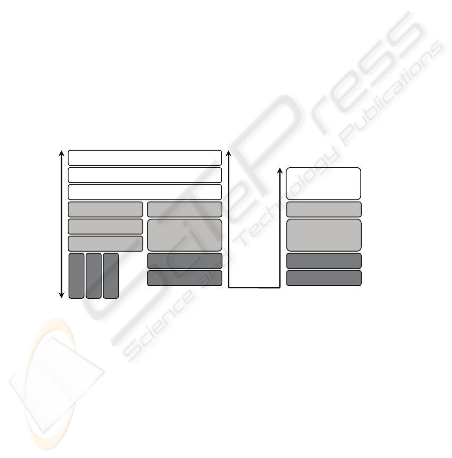
Fig. 1. ZigBee Gateway architecture: The IP stack is terminated at the Gateway as is the Zig-
Bee Stack; the Gateway provides translation between the respective stacks.
A ZigBee Gateway is intended to provide an interface between ZigBee and IP devices
through an abstracted interface on the IP side. The IP device is isolated from the Zig-
Bee protocol by that interface, see Fig. 1. The ZigBee Gateway translates both ad-
dresses and commands between ZigBee and IP.
Zi
g
Bee Gatewa
y
A
pp
lication Services
Zi
g
Bee Gatewa
y
Trans
p
ort Services
TCP
,
UDP
IP
802.15.4 MAC
Ethern
Wire-
…
802.15.4 PHY
App
. Su
pp
ort
Network Layer
DHCP
,
SNMP
,
App
lication
(
Java
,
…
)
802.15.4 PHY
802.15.4 MAC
App
. Su
pp
ort
Network Layer
Embedded Ap-
plication
ZigBee Gateway
ZigBee Node
69
3.2 ZigBee Bridge
A ZigBee Bridge extends the ZigBee network over an IP based network. Since the
specific physical and Medium Access layers are not pertinent as long as the network
layer is IP based, the ZigBee Bridge will work over Ethernet or WiFi types of de-
vices. The ZigBee network layer is continuous among ZigBee devices by overlaying
them on the TCP/IP network’s transport layer. The ZigBee Bridge makes the IP con-
nectivity transparent to the ZigBee devices. In an alternative case, a ZigBee Bridge
may be used to communicate with IP devices that are executing the ZigBee stack and
communicate through a ZigBee network layer while the IP device behaves like an
extension of the ZigBee network, see Fig. 2. In this case geographically separated
clusters of ZigBee devices may communicate with each other through an IP backbone
using ZigBee Bridge devices. These networks may be separated by some distance, but
they nonetheless share a single coordinator, PAN ID, and address space.
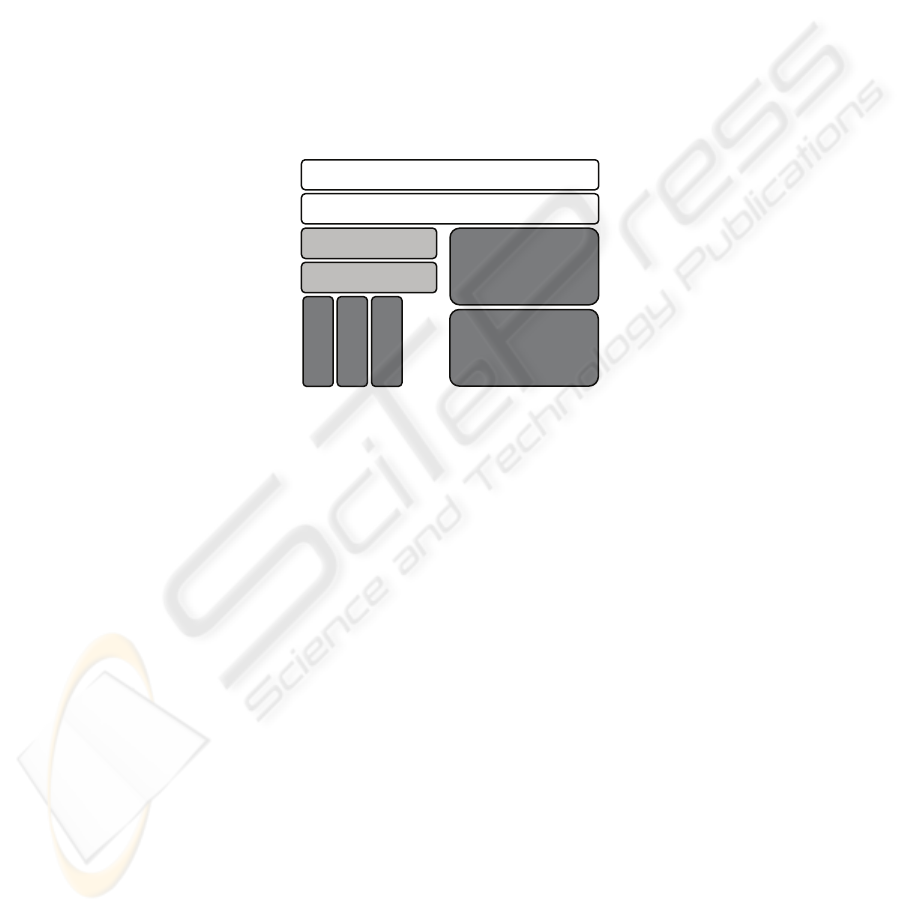
Fig. 2. ZigBee Bridge architecture: The ZigBee stack runs over the IEEE 802.15.4 MAC and is
encapsulated to run over the TCP/IP stack.
A single cluster of ZigBee devices may utilize an IP backbone to provide low-cost
routing within a PAN. For example, in a multistory building it is possible to place a
ZigBee Bridge on each story. Communication to nearby devices would occur through
wireless links but communication between floors would tend to occur through the IP
backbone that provides fast and reliable wired links with low routing cost.
3.3 ZigBee Application Layer Services
The key to communication among devices on a ZigBee network is agreement on a
profile. This profile permits a series of six device types to exchange control messages
to form a wireless application [4]. These devices are architected to exchange well
know messages to effect control. For that exchange they use key value pair service.
The key value pair service, which is a part of ZigBee profile, allows attributes, de-
fined in the application objects, to be manipulated by employing a state variable ap-
proach with get response, get, set and event transactions. The latter two transactions
can be sent with an acknowledgement request, resulting in the corresponding set
response and event response transactions, respectively. Additionally, key value pair
Zi
g
Bee Network La
y
er
Brid
g
e Routin
g
La
y
er
TCP
,
UDP
IP
802.15.4 MAC
Ethern
Wire-
…
802.15.4 PHY
70

service uses tagged data structures using compressed XML. Together, this solution
provides an elegant command and control mechanism for small devices with extensi-
bility to enable gateways to expand to full XML.
4 Conclusions
This paper deals with sensor networking frameworks founded on object-oriented
architectures IEEE 1451.1 and IEEE 802.15.4, which are capable to support effi-
ciently intelligent sensors. The contribution is focused on ZigBee dedicated software
architectures that mediate access from Internet to wireless sensors with ZigBee inter-
faces. Two types of ZigBee devices for total connectivity can be distinguished: gate-
ways and bridges. Although both types of devices may accommodate various applica-
tions, upon reviewing application’s requirements one of these types will usually
prove superior. By the way, needed future standardization of those devices will en-
able multiple vendors to interoperate and provide a high-class solution to ZigBee
users.
Next work of the authors’ research group will focus on detailed descriptions of
concrete implementations of case studies devoted to such application domains as
home security and safety critical industrial devices.
Acknowledgements
This research has been partly funded by the Czech Ministry of Education in frame of
the Research Intention No. MSM 0021630503 MIKROSYN: New Trends in Micro-
electronic Systems and Nanotechnologies; and by the Grant Agency of the Czech
Republic through the grants GACR 102/05/0723: A Framework for Formal Specifica-
tions and Prototyping of Information System's Network Applications, and GACR
102/05/0467: Architectures of Embedded Systems Networks.
References
1. IEEE 1451.1: Standard for a Smart Transducer Interface for Sensors and Actuators -- Net-
work Capable Application Processor (NCAP) Information Model, IEEE, New York (2000)
2. IEEE 1451.2: Standard for a Smart Transducer Inter-face for Sensors and Actuators --
Transducer to Microprocessor Communication Protocols and Transducer Electronic Data
Sheet (TEDS) Formats, IEEE, New York (1997)
3. Sveda, M., et al.: Introduction to Industrial Sensor Networking, In: Ilyas, M., Mahgoub, I.
(Eds.): Handbook of Sensor Networks: Compact Wireless and Wired Sensing Systems,
CRC Press LLC, Boca Raton, FL (2005)
4. Kinney, P.: Gateways: Beyond the sensors networks. Zigbee Alliance, www.zigbee.org
5. Lee, E.A.: What’s Ahead for Embedded Software. IEEE Computer, Vol.33, No.9 (2000)
18-26
6. ZigBee Alliance: ZigBee Specification v 1.0. ZigBee Alliance Board of Directors (2004)
Website http://www.zigbee.org/
71
