
A COMPARATIVE STUDY OF 802.11 AND 802.11E WIRELESS
LAN STANDARDS
Fedoua Didi
University Abou Bekr Belkaid of Tlemcen Algeria
Houda Labiod
ENST of Paris France
Guy Pujolle
LIP6 of University Pierre and Marie Currie France
Keywords: IEEE 802.11, Medium Access Control (MAC), Quality of Service (QoS), Distributed Coordination
Function (DCF), Point Coordination Function (PCF), Hybrid Coordination Function (HCF), IEEE 802.11e,
Network Simulator (NS).
Abstract: Quality of service (QoS) is a key problem in wireless environments where bandwidth is scarce and channel
conditions are time varying and sometimes highly loss. Although IEEE 802.11 wireless LAN (WLAN) is
the most widely used WLAN standard today, and the upcoming IEEE 802.11e QoS enhancement standard
exists and introduces the QoS for supporting multimedia applications. This paper compares the propositions
of standard IEEE 802.11e with the standard IEEE 802.11 without QoS, a simulation of these standards is
performed by using the NS simulator. A discussion is presented in detail using simulation-based evaluations
and we let us confirm the QoS of IEEE 802.11e compared to IEEE 802.11, but we have detected some
weaknesses of 802.11e. It starves the low priority traffic in case of high load, and leads to higher collision
rates, and did not make a good estimate of weight of queues, so there is an unbalance enters the flows with
high priorities. We finish with a conclusion.
1 INTRODUCTION
IEEE 802.11 wireless LAN (WLAN) (IEEE 802.11
WG, 1999) is one of the most deployed wireless
technologies all over the world and is likely to play a
major role in next generation wireless
communications networks. The main characteristics
of 802.11WLAN technology are simplicity,
flexibility and cost effectiveness. This technology
provides people with a ubiquitous communications
and computing environment in offices, hospitals,
campuses, factories, airports, stock markets, etc.
Simultaneously, multimedia applications have
experienced an explosive growth. People are now
requiring to receive high speed video, audio, voice
and Web services even when they are moving in
offices or travelling around campuses. However,
multimedia applications require some quality of
service support such as guaranteed bandwidth,
delay, jitter and error rate. Guaranteeing those QoS
requirements in 802.11 WLAN is very challenging
due to the QoS unaware functions of its medium
access control (MAC) layer and the noisy and
variable physical (PHY) layer characteristics. In this
paper we compare the two standards 802.11 and
802.11e by using a simulation with Network
Simulator (NS) and present a detailed discussion of
results. The paper is organized as follows. Section 2
introduces an overview of IEEE 802.11 WLAN and
section 3 introduces the QoS enhancement standard
802.11e. In section 4, we present the model of
simulation with its parameters and a detailed
discussion of results. We finish with a conclusion.
133
Didi F., Labiod H. and Pujolle G. (2006).
A COMPARATIVE STUDY OF 802.11 AND 802.11E WIRELESS LAN STANDARDS.
In Proceedings of WEBIST 2006 - Second International Conference on Web Information Systems and Technologies - Internet Technology / Web
Interface and Applications, pages 133-139
DOI: 10.5220/0001238601330139
Copyright
c
SciTePress
2 DESCRIPTION OF 802.11
STANDARD
2.1 Introduction
The IEEE 802.11 WLAN standard covers the MAC
sub-layer and the physical (PHY) layer of the open
system interconnection (OSI) network reference
model (IEEE 802.11 WG, 1999). Logical link
control (LLC) sub-layer is specified in the IEEE
802.2 standard. This architecture provides a
transparent interface to the higher layer users:
stations (STAs) may move, roam through an 802.11
WLAN and still appear as stationary to 802.2 LLC
sub-layer and above. This allows existing TCP/IP
protocols to run over IEEE 802.11 WLAN just like
wired Ethernet deployed. We can show (Aad I,
Castelluccia C., 2001) different standardization
activities done at IEEE 802.11 PHY and MAC
layers.
The standard comprises three PHY layers, which
are an InfraRed (IR) base band PHY; a frequency
hopping spread spectrum (FHSS) radio and direct
sequence spread spectrum (DSSS) radio. These
entire choices support both 1 and 2Mbps PHY rate.
In 1999, the IEEE define two high rate: 802.11b in
the 2.4GHz band with 11Mbps, based on DSSS
technology; and 802.11a in the 5GHz band with
54Mbps, based on orthogonal frequency division
multiplexing (OFDM) technology. Recently,
802.11g is finalized to be an extension of 802.11b
with 54Mbps in the 2.4GHz band.
2.2 The MAC Sub-Layer of 802.11
It defines two medium access coordination
functions, the basic Distributed Coordination
Function (DCF) and the optional Point Coordination
Function (PCF) (IEEE 802.11 WG, 1999).
Asynchronous transmission is provided by DCF
which operate in contention-based period, and
synchronous transmission is provided by PCF that
basically implements a polling-based access which
operate in contention free period. A group of STAs
coordinated by DCF or PCF is formally called a
basic set (BSS). The area covered by BSS is the
basic service area (BSA), like a cell in a cellular
mobile network.
Two modes exist: ad-hoc mode and
infrastructure mode. The first mode forms an Independent
BSS (IBSS) where the STAs can directly communicate
with each other by using only the DCF, without any
connectivity to any wired backbone. In the second mode,
the STAs communicate with the wired backbone through
the bridge of access point (AP), which can use both DCF
and PCF.
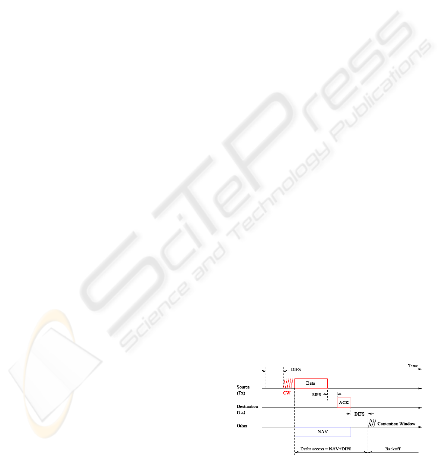
2.2.1 Distributed Coordination Function
DCF is a distributed medium access scheme based
on carrier sense multiple accesses with collision
avoidance (CSMA/CA) protocol. In this mode, the
STAs must sense the medium before transmitting a
packet, if the medium is found idle for an interval of
time longer than a Distributed InterFrame Space
(DIFS); the STA can transmit the packet
immediately (IEEE 802.11 WG, 1999), meanwhile
other STAs defer their transmission and adjusting
their Network Allocation Vector (NAV) which is a
local timer. Then the backoff process starts, the STA
compute a random Backoff_timer=rand [0,
CW]*slot time, where CWmin ≤ CW (window
contention parameter) ≤ CWmax and slot time
depends on the PHY layer type. The backoff timer is
decreased only when the medium is idle. Each time
the medium becomes idle, the STA waits for a DIFS
and continuously decrements the backoff timer. As
soon as the backoff expires, the STA is authorized to
access the medium. Obviously, a collision occurs if
two or more STAs start transmission simultaneously.
If the acknowledgement, used to notify that the
transmitted frame has been successfully received
(see Figure 1), is not received, the sender assumes
that a collision was occurred, so it schedules a
retransmission and enters the backoff process again.
To reduce the probability of collisions, after each
unsuccessful transmission attempt, the CW is
doubled until a predefined maximum value CWmax
is reached. But after each successful transmission,
the CW is reset to a fixed minimum value CWmin.
Two carrier sensing mechanisms are possible, PHY
carrier sensing at air interface and virtual carrier
sensing at PHY MAC layer. Virtual carrier sensing
can be used by an STA to inform all other STAS in
the same BSS how long the channel will be reserved
for its frame transmission. On this purpose, the
sender can set a duration field in the MAC header of
data frames. Then other STAS can update their
NAVS to indicate this duration, and will not start
transmission before the updated NAV timers reach
zero.
Figure 1: Basic DCF CSMA/CA.
WEBIST 2006 - INTERNET TECHNOLOGY
134

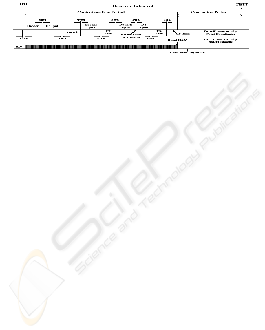
2.2.2 PCF: Point Coordination Function
PCF uses a centralised polling scheme, which
requires the AP as a point coordinator (PC) in a
BSS. The channel access time is divided into
periodic intervals named beacon intervals, see
Figure 2. The beacon interval is composed of a
contention-free period (CFP) and a contention
period (CP). During the CP, the PC maintains a list
of registered STAs and polls each STA according to
its list. Then, when a STA is polled, its gets the
permission to transmit data frame. Since every STA
is permitted a maximum length of frame to transmit,
the maximum CFP duration for all the STAs can be
known and decided by the PC, which is called
CFP_max_duration. The time used by the PC to
generate beacon frames is called target beacon
transmission time (TBTT). In the beacon, the PC
denotes the next TBTT and broadcast it to all the
others in the BSS. In order to ensure that no DCF
STAs are able to interrupt the operation of the PCF,
a PC waits for a PCF InterFrame Space (PIFS),
which is shorter than DIFS, to start the PCF. Then,
all the others STAs set their NAVs to the values of
CFP_max_duration time, or the remaining duration
of CFP in case of delayed beacon. During the CP,
the DCF scheme is used, and the beacon interval
must allow at least one DCF data frame to be
transmitted. A typical medium access sequence
during PCF is shown in Figure 2. When a PC polls
an STA, it can piggyback the data frames to the STA
together with the CF-poll, then the STA sends back
data frame piggybacked with an ACK after a SIFS
interval. When the PC polls the next STA, it
piggybacks not only the data frame to the
destination, but also an ACK to the previous
successful transmission. Note that almost all packet
transmissions are separated by the SIFS except for
one scenario: if the polled STA does not respond the
AP within a PIFS period, the AP will poll the
following STA. Silent STAs are removed from the
polling list after several periods and may be polled
again at beginning of the next CFP. At any time, the
PC can terminate the CFP by transmitting a CF-end
packet, then all the STAs in the BSS should reset
their NAVs and attempt to transmit during the CP.
Normally, PCF uses a round robin scheduler to poll
each STA sequentially in the order of polling list,
but priority based polling mechanisms can also be
used if different QoS levels are requested by
different STAs.
3 DESCRIPTION OF 802.11E
STANDARD
3.1 HCF: Hybrid Coordination
Function
There are many new features in 802.11e draft 4.2
(IEEE 802.11 WG, 2003). In this section, we will
briefly describe HCF. HCF is composed of two
access methods: contention-based channel access
(called EDCF) and controlled channel access
mechanisms. One main feature of HCF is to
introduce four access category (AC) queues and
eight traffic stream (TS) queues at MAC layer.
When a frame arrives at MAC layer, it is tagged
with a traffic priority identifier (TID) according to
its QoS requirements. Which can take the values
from 0 to 15. The frames with TID values from 0 to
7 are mapped into four AC queues using EDCF
access rule. On the other hand, frames with TID
values from 8 to 15 are mapped into eight TS queues
using HCF controlled channel access rule. The
reason of separating TS queues from AC queues is
to support strict parameterized QoS at TS queues
while prioritized QoS is supported at AC queues.
Another main feature of the HCF is the concept of
transmission opportunity (TXOP), which is the time
interval permitted, for a particular STA to transmit
packets. During the TXOP, there can be a series of
frames transmitted by an STA separated by SIFS.
The TXOP is called either EDCF-TXOP, when it is
obtained by winning a successful EDCF contention;
or polled-TXOP, when it is obtained by receiving a
QoS CF-poll frame from the QoS-enhanced AP
(QAP). The maximum value of TXOP is called
TXOPLimit, which is determined by QAP.
3.2 Enhanced Distributed
Coordination Function (EDCF)
The EDCF is designed for the contention-based
prioritized QoS support. Each QoS-enhanced STA
(QSTA) has 4 queues (ACs), to support 8 user
priorities (UPs). Therefore, one or more UPs are
mapped to the same AC queue. This comes from the
observation that usually eight kinds of applications
A COMPARATIVE STUDY OF 802.11 AND 802.11E WIRELESS LAN STANDARDS
135
do not transmit frames simultaneously, and using
less ACs than UPs reduces the MAC layer
overheads. Each AC queue works as an independent
DCF STA and uses its own backoff parameters. In
EDCF, two main methods are introduced to support
service differentiation: The first one uses different
InterFrame Space (IFS) sizes for different ACs. A
new kind of IFS called Arbitrary IFS (AIFS) is used
in EDCF, instead of DIFS in DCF. AIFS[AC] =
AIFSN[AC] * SlotTime + SIFS, where the default
value of the arbitration inter frame spacing number
(AIFSN) is defined as either 1 or 2 (IEEE 802.11
WG, 2003).When AIFSN=1, high priority queues
AC1, AC2 and AC3 have AIFS value equal to PIFS.
When AIFSN=2, the low priority queue AC0 has
AIFS value of DIFS. When a frame arrives at an
empty AC queue and the medium has been idle
longer than AIFS [AC]+SlotTime, the frame is
transmitted immediately .If the channel is busy, the
arriving packet in each AC has to wait until the
medium becomes idle and then defer for
AIFS+SlotTime. So the AC with the smaller AIFS
has the higher priority. For example, the earliest
transmission time for high priority queue is to wait
for PIFS+SlotTime=DIFS, while the earliest
transmission time for best effort queue is to wait for
DIFS+ SlotTime. The second method consists in
allocating different CW sizes for different ACs.
Assigning a short CWsize to high priority AC
ensures that in most cases, high-priority AC is able
to transmit packets ahead of low-priority one. If the
backoff counters of two or more parallel ACs in one
QSTA reach zero at the same time, a scheduler
inside the QSTA will avoid the virtual collision by
granting the EDCF-TXOP to the highest priority
AC. At the same time, the other colliding ACs will
enter a backoff process and double the CW sizes as
if there is an external collision. In this way, EDCF is
supposed to improve the performance of DCF under
congested conditions. The default values of AIFSN
[AC], CWmin [AC], CWmax [AC] and TXOPLimit
[AC] are announced by the QAP in beacon frames,
and the 802.11e standard also allows the QAP to
adapt these parameters dynamically depending on
network conditions (IEEE 802.11 WG, 2003). But
how to adapt to the channel has not been defined by
the standard and remains an open research issue.
3.3 HCF Controlled Channel Access
The HCF controlled channel access mechanism is
designed for the parameterized QoS support, which
combines the advantages of PCF and DCF. HCF can
start the controlled channel access mechanism in
both CFP and CP intervals, whereas PCF is only
allowed in CFP. A typical 802.11e beacon interval ,
is composed of alternated modes of optional CFP
and CP. During the CP, a new contention-free period
named controlled access phase (CAP) is introduced.
HCF can start a CAP by sending downlink QoS-
frames or QoS CP-Poll frames to allocate polled-
TXOP to different QSTAs after the medium remains
idle for at least PIFS interval. Then the remaining
time of the CP can be used by EDCF. This flexible
contention-free scheme makes PCF and CFP useless
and thus optional in the 802.11e standard. For
example, in order to support audio traffic with a
maximum latency of 20 millisecond (ms) using PCF,
the beacon interval should be no more than 20 ms
since the fixed portion of CP forces the audio traffic
to wait for the next poll. On the other hand, the HCF
controlled channel access can increase the polling
frequency by initiating CAP at any time, thus
guarantee the delay bound with any size of beacon
interval. So there is no need to reduce the beacon
interval size that increases the overheads. In HCF
controlled channel access mechanism, QoS
guarantee is based on the traffic specification
(TSPEC) negotiation between the QAP and the
QSTAs. Before transmitting any frame that requires
the parameterized QoS, a virtual connection called
traffic stream (TS) is established. In order to set up a
TS, a set of TSPEC parameters (such as mean data
rate, nominal frame size, maximum service interval,
delay bound, etc.) are exchanged between the QAP
and the corresponding QSTAs. Based on these
TSPEC parameters, the QAP scheduler computes the
duration of polled-TXOP for each QSTA, and
allocates the polled-TXOP to each QSTA. Then the
scheduler in each QSTA allocates the TXOP for
different TS queue according to the priority order. A
Figure 2: PCF and DCF cycles.
WEBIST 2006 - INTERNET TECHNOLOGY
136

simple round-robin scheduler is proposed in the
IEEE 802.11e draft 4.2 (IEEE 802.11 WG, 2003).
The simple scheduler uses the following mandatory
TSPEC parameters: mean data rate, nominal MAC
frame size and maximum service interval or delay
bound. Note that the maximum service interval
requirement of each TS corresponds to the
maximum time interval between the start of two
successive TXOPs. If this value is small, it can
provide low delay but introduce more CF-Poll
frames. If different TS have different maximum
service interval requirements, the scheduler will
select the minimum value of all maximum service
interval requests of all admitted streams for
scheduling. Moreover, the QAP is allowed to use an
admission control algorithm to determine whether or
not to allow new TS into its BSS. During a CFP, the
medium is fully controlled by QAP. During a CP, it
can also grab the medium whenever it wants (after a
PIFS idle time). After receiving a QoS CF-poll
frame, a polled QSTA is allowed to transmit
multiple MAC frames denoted by contention-free
burst (CFB), with the total access time not exceeding
the TXOPLimit.
4 SIMULATION-BASED
EVALUATIONS OF
OS-ENHANCED SCHEMES
In (Benveniste M. et al., 2001), (Qiang Ni et al.,
2004), different simulations have been conducted
with different topology and parameters of EDCF. To
evaluate the performance of DCF and EDCF
schemes, we use NS-2 (Anelli A et al.), there is no
mobility in the system, each station operates at IEEE
802.11b PHY and transmits three types of traffic
(audio, video and data traffic) to each other. The
DCF MAC parameters are listed in Table 1 and
Table 1: DCF parameters.
SIFS 16µs MAC header 28bytes
DIFS 34µs PLCP header
length
4µs
ACK
size
14bytes Preamble length 20µs
PHY
rate
36Mbps CWmin 15
Slot
time
9µs WCmax 1023
EDCF parameters are: for audioPCM (Wmin=7,
Wmax=15, AIFSN=1, Packet size in bytes=160,
Packet interval in ms=20, Sending rate in KB/s=8),
for Video MPEG4 (15,35,1,1280,16,80), for Video
VBV(15,31,2, 660,26,25), for Data (31,1023, 2,
1600, 12.5,128).We use CBR/UDP traffic sources.
We vary the load rate by increasing the number of
STAs from 0 to 6.
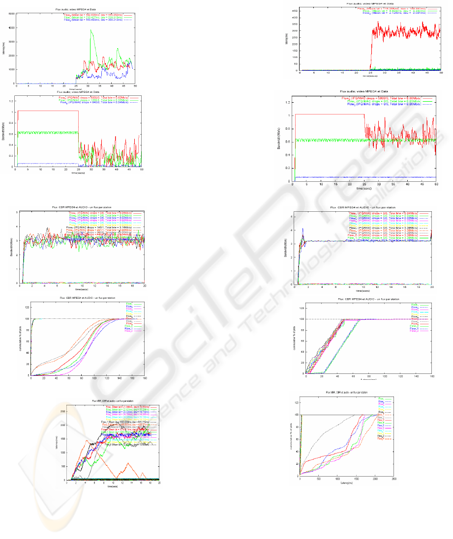
Figure 2 shows the simulation results for the
bandwidth, and latency. We can see that average
throughput of three kinds of flows per STA are
stable and sufficient as long as the channel load rate
is less than 70% at the 25th second, after all flows
degrade themselves dramatically in DCF, but not in
EDCF. And we let us notice, that there is a high rate
loss of packets in DCF, and a low rate loss of
packets in EDCF. We see also that latency is good
for all flows, but at the 25
th
second, it increases
significantly in DCF. On the other hand, in EDCF
only data suffer by a high latency. The evolution of
latency in DCF, in function of channel load rate is
dramatic for all flows after 70% rate, but in EDCF
after 60% only data flow degrade themselves. Figure
3 shows the advantages of HCF controlled channel
access mechanism compared to EDCF, we simulate
an topology with 13 STAs (STA 0 is the AP), six
STAs transmit each one a audio flow, and the six
others transmit a video flow (CBR MPEG4) at
AP.We notice that the throughput (D) is stable and
distributed well on all the STAs by HCF, which is
not the case for EDCF, where D fluctuate too much
quickly, what indicates a bad management of the
bandwidth. For EDCF, the latency increases all
gently when the channel load rate increases but only
for audio flows, for the video flows, the latency
increase brutally. For HCF, the evolution of latency
is the same for all flows. Figure 4 shows the
limitations of HCF by a simulation of 19 STAs (the
STA 0 is the AP) and STA1 to STA6 transmits a
PCM Audio flows with inter arrival time of 4.7ms,
Packet size of 160bytes, Sending rate of 64Kbps and
a priority of 6. STA7 to STA12 transmits a VBR
(variable bit rate) video flows with Arrival period
almost equal to 26, Packet size almost equal to 660,
Sending rate almost equal to 200 and a priority of 5.
STA13 to STA18 transmits a MPEG4 video flows
with Arrival period=2, Packet size=800, Sending
rate=3200 and a priority of 4. Let us notice that
latency of VBR flows fluctuate and increase
dramatically, what is not the case of the other flows.
This is with the fact that the AP is unable to make a
good estimate of the size of the queues for a good
scheduling.
A COMPARATIVE STUDY OF 802.11 AND 802.11E WIRELESS LAN STANDARDS
137
5 CONCLUSION
The results of simulation show that the protocol
DCF can only support best-effort services, not any
QoS guarantees, all the STAs in one BSS compete
for the resources and channel with the same
priorities. There is no differentiation mechanism to
guarantee bandwidth, packet delay and jitter for high
priority STAs or multimedia flows. The EDCF
protocol show to be the best choice for high priority
Figure 3: Throughput and latency performance for DCF and EDCF.
Figure 4: Throughput and channel load for EDCF and HCF Controlled channel access.
Figure 5: Throughput for EDCF and HCF Controlled channel access.
WEBIST 2006 - INTERNET TECHNOLOGY
138

traffic, but it starves the low priority traffic in case
of high load, and leads to higher collision rates.
Furthermore, when channel is 90% loaded, the
throughput of audio and video start to decrease,
which means that admission control for audio and
video is required during very high load. The HCF
protocol has a drawback, that AP did not make a
good estimate of weight of queues, so there is an
unbalance (il y a un désequilibre dans le partage de
la bp entre les flux multimedia) enters the flows with
high priorities. A HCF protocol which mitigates the
disadvantages of HCF was developed, and we intend
to evaluate it in future research. We can also propose
a new mechanisms of QoS, which can fill the faults
of the standard and evaluates their effectiveness by a
simulation.
ACKNOWLEDGMENTS
We would like to thank mister Salissou for his
valuable help in performing a large set of simulation.
REFERENCES
IEEE 802.11 WG, Reference number ISO/IEC 8802-
11:1999(E) Std 802.11, 1999 edition International
Standard {for} Information Technology –
Telecommunications and information exchange
between systems-Local and metropolitan area
network-Specific Requirements – Part 11:Wirelesss
LAN Medium Access Control (MAC) and Physical
Layer (PHY) specifications, 1999.
IEEE 802.11 WG, Draft Supplement to Standard for
Telecommunications and information exchange
between systems-Local and metropolitan area
network-Specific Requirements – Part 11: Wirelesss
LAN Medium Access Control (MAC) and Physical
Layer (PHY) specifications. Enhancements for QoS,
IEEE 802.11e/Draft 4.2, February 2003.
Aad I, Castelluccia C. Differentiation mechanisms for
IEEE 802.11, Proc. IEEE Infocom 2001, Anchorage,
Alaska, USA, April 2001;1:209-218.
Anelli A, Horlait C. Manuel NS version 2 : Principes de
conception et d’utilisation . UPMC- LIP6.
Bonin J M. Introduction à la simulation d’un réseau à
travers NS. Access date 2002.
Hung P. NS2 Tutorial .14 Juin 1999
Carta A. A Network Topology Presentation Tool. Project
Report, UC Berkeley 1993
Benveniste M, Chesson G, Hoeben M, Singla A, et. Al.
EDCF proposed draft text. IEEE 802.11e working
document 802.11-01/131r1, March 2001.
Lindgren A, Almquist A and Schelen O. Evaluation of
quality of services schemes for IEEE 802.11 wireless
LANs. Proc. Of the 26
th
Annual IEEE Conference on
local computer networks (LCN 2001), Tampa,
Florida, USA,November 15-16, 2001; 348-351.
Qiang Ni, Romdhani L, Turletti T. A Survey of QoS
Enhancements for IEEE 802.11 Wireless LAN. Et al.
Journal of Wireless Communications and Mobile
Computing, Wiley. 2004: Volume 4, Issue 5: pp.547-
566.
A COMPARATIVE STUDY OF 802.11 AND 802.11E WIRELESS LAN STANDARDS
139
